Sulfur/reduced graphite oxide and dual-anion solid polymer‒electrolyte integrated structure for high-loading practical all-solid-state lithium–sulfur batteries

Introduction
Large-scale applications such as electric vehicles (EVs) and stationary storage devices require rechargeable batteries that can operate safely at medium-to-high temperatures and with high energy (Wh/L, Wh/kg) and power (W/kg, W/cm3) densities. Among the various rechargeable batteries, lithium-ion batteries (LIBs) are promising because of their high energy and power densities, long cycle lives, and low self–discharge rates1,2,3,4. However, LIBs cannot currently satisfy the performance requirements of internal combustion vehicles because their energy densities are insufficient ( ~ 200 Wh/kg) or their usage lifespans are too short5,6. Therefore, improved energy density is necessary to satisfy the requirements of EVs (electric battery range: 300–400 miles)7. Moreover, additional stringent requirements, such as low price, high safety, and long life, apply to rechargeable batteries for EVs. Generally, rechargeable LIBs consist of a cathode (which influences the battery capacity), an anode (which influences the battery life), an electrolyte that acts as a medium for Li-ion movement, and a separator that prevents direct contact between the cathode and anode8,9. The battery capacity performance is primarily determined by the cathode and anode characteristics, whereas battery safety is determined by the electrolyte and separator. Therefore, effective selection of and improvements in the cathode, anode, and electrolyte are important for improving the overall battery performance.
Li–S batteries (LSBs) have attracted considerable attention as next-generation batteries. S, which can be used as an active cathode material, is light, naturally abundant, and economical10. Additionally, LSBs have a high theoretical energy density of 2500 Wh/kg (2800 Wh/L, assuming a complete reaction with Li2S), which is approximately four times greater than that of commercial LIBs10,11,12. Typical LSBs consist of a Li anode (−), S composite cathode (+), separator, and organic liquid electrolyte. In most liquid LSBs, the reaction involves multiple steps. S is present in the form of octa-S (cyclo-S8), which is the most stable structure at room temperature and has a low conductivity of 5 × 10⁻³⁰ S/cm at 25 °C13. During the discharge process, cyclo-S8 undergoes numerous structural and morphological transformations, and electrolyte-soluble Li polysulfides (LiPSs), such as Li2Sx (4 ≤ x ≤ 8) and insoluble Li2S2/Li2S, are formed14. However, the presence of soluble LiPSs in the electrolyte decreases the utilization and capacity of the active material. Consequently, the LSB operating mechanism hinders its cycling performance. Additionally, the highly soluble LiPS intermediate products pass through the separator and diffuse to the Li anode, where they are reduced to insoluble Li2S2/Li2S and deposited on the anode surface, thereby causing active material loss15. This random deposition degrades the electrode, and LiPS diffusion creates an internal redox shuttle, which yields a low Coulombic efficiency (CE)16.
Several methods have been devised to address the low conductivity of S and the LiPS dissolution phenomenon and, thus, to improve the electrochemical performance of LSBs. These approaches include the design of S/C composites or conducting materials and the encapsulation of S particles in conducting materials17,18,19,20,21,22,23. For example, Wang et al.17 prepared a three-dimensional holey graphene/polyacrylonitrile S composite for high-mass-loading LSBs, which had an ultralow-capacity fading rate of 0.012% per cycle after 1500 continuous cycles and a specific capacity of 581.6 mAh g−1 at 2 C. Gong et al.18 chemically synthesized a graphene quantum dot/sulfur (GQD/S) composite for LSBs; a high initial discharge capacity of 1125 mAh g−1 at 0.1 C was obtained in a GQD/S cell. Furthermore, Sovezi et al.19 prepared an organic polymer (honeycomb polyaniline–dodecyl benzene sulfonic acid)/S cathode for LSBs with an initial specific capacity of 848 mAh g−1 at 0.2 C and a CE of 99.3% over 100 cycles.
The use of metallic compounds, catalysts (C2N, molybdenum disulfide), and metal oxides as S hosts in LSBs has been extensively investigated20,21,22,23,24. However, the S-electrode volume expands during discharge, with the density difference between S and Li2S generating approximately 80% of this expansion. Consequently, the mechanical structure of the electrode becomes unstable. When the electrode cracks, the active materials do not come into contact with the conductive agent, which causes capacity decay or battery failure15,17. Overall, the above methods can effectively solve individual problems, but their capacity to improve overall battery performance and safety is limited.
In most LSBs, Li is used as the anode because of its high theoretical specific capacity (3860 mAh g−1), high Li-ion supply, low density (0.59 g cm−1), and low negative electrochemical potential ( − 3.040 V vs. the standard hydrogen electrode)14,15. However, the use of Li generates safety concerns regarding the formation of Li dendrites. Dendrite growth during LSB charging can induce internal short circuits and thermal runaways in cells featuring liquid electrolytes25. The risk of severe accidents is particularly high when combustible liquid-type organic electrolytes are used. However, all-solid-state (ASS) LSBs can mitigate LiPS dissolution and improve cell safety. ASS-LSBs have an S-containing cathode, a solid polymer electrolyte (SPE), and a Li anode. SPE can potentially prevent LiPS dissolution and safety problems owing to its high thermal and electrochemical stability. This electrolyte, which acts as a flexible and dense physical barrier between the Li anode and S cathode, has slow exothermal decomposition and no volatile components, further minimizing explosion hazards in the case of fire26,27. SPEs are less toxic than liquid organic electrolytes when ignited28, and SPE-based batteries offer flexibility in terms of their shape and mechanical elasticity29. Thin and flexible ASS-LSBs are potentially applicable to future smartphones, tablet computers, and electric transportation and are particularly suitable for applications requiring high energy density and safety.
Generally, the prerequisites for LSB SPEs are good ionic conductivity, low LiPS solubility in the electrolyte, reactivity with the Li anode, good interfacial properties, reasonable mechanical integrity, and thermal and electrochemical stability30,31,32,33,34. Replacing the liquid organic electrolyte with an SPE prevents the loss of S active material and Li dendrite growth, and an SPE with high ionic conductivity and good electrochemical stability can improve the electrochemical performance and cycling stability of a battery. Many studies have investigated the ability of SPEs to prevent LiPS dissolution, shuttle effects, and Li dendrite formation35,36,37,38,39,40,41,42,43,44. For example, Zhu et al.35 prepared a bilayer framework by integrating a three-dimensional carbon nanofiber/S cathode with a one-dimensional ceramic Li0.33La0.557TiO3 nanofiber–poly(ethylene oxide) (PEO) solid composite electrolyte to serve as both the cathode and electrolyte for ASS-LSBs. Their framework revealed a stabilized cycling performance ( > 99% CE with 415 mAh g−1 discharge capacity after 50 cycles) and accommodated large volume changes owing to its mechanical robustness. Furthermore, Bag et al.37 synthesized a polymer-ceramic-based SPE (poly(vinylidene fluoride (PVDF)–Li6.5La2.5Ba0.5ZrTaO12) for LSBs, which demonstrated a high initial specific capacity of 936 mAh g−1 at 0.1 C at 25 °C and stable performance over 80 continuous cycles (610 mAh g−1). According to Zhang et al.42, ASS-LSBs prepared via a PEO/PE/lithium bis(trifluoromethanesulfonyl)imide (LiTFSI) SPE and binder-free S@CTT/MXene electrodes exhibited excellent safety characteristics and a stable cycling stability of approximately 584 mAh g−1, even after 100 cycles at 0.12 C. However, ASS-LSBs are an emerging research interest, and their stability and capacity characteristics are currently inadequate. For the ASS-LSBs reported to date, the electrodes had a low S content ( < 50 wt.%) and were fabricated with a low capacity ( < 1 Ah). Although these ASS-LSBs benefit from high electrochemical stability and safety, ASS-LSBs with high S contents and stacked structures enabling high capacity for practical applications in rechargeable batteries are essential.
In this study, an electrode with high S content and a stacked structure was developed for use in partial ASS-LSBs. In this approach, S particles were hydrothermally dispersed in reduced graphite oxide (rGO) and used as a cathode material to improve the conductivity of the S-active material. Dual anions were incorporated by employing a stable SPE for the S cathode for the first time. In detail, an ionic liquid-containing crosslinked PEO–Li bis(fluoromethanesulfonyl)imide–N-butyl-N-methylpyrrolidinium bis(trifluoromethanesulfonyl) imide-based (PEO-LiFSI0.1(Pyr14TFSI)0.4) SPE was prepared and hot-pressed with an S/rGO cathode into an integrated electrode, serving as both the cathode and electrolyte, to suppress dendrite growth and the shuttle effect. The elaborately designed dual-anion SPE capitalizes on a synergistic effect, amalgamating the advantageous traits of both anions. Bis(fluorosulfonyl)imide (FSI) anions from LiFSI lithium salt enhance compatibility with the Li anode by facilitating the formation of a LiF-rich SEI layer, thereby increasing cycling performance stability45,46,47. Moreover, bis(trifluoromethanesulfonyl)imide (TFSI) anions from Pyr14TFSI ionic liquid provide high conductivity and widen the electrochemical stability window, thereby enhancing both the rate capability and cycle stability48,49,50. Finally, the cathode and SPE fabrication methods were employed to fabricate a 3-Ah ASS-LSB51,52.
Experimental
Preparation of the S/rGO composite
Functionalized graphene oxide (rGO) was synthesized from natural graphite via a modified Hummers’ method45. Figure 1a shows a schematic of the S/rGO composite preparation. First, a mixture of graphite flakes (3.0 g) and KMnO4 (18.0 g) was slowly added to a solution containing H2SO4 (360 mL) and H3PO4 (40 mL); the temperature was maintained at 35 °C ( ± 3 °C). The resulting solution was stirred for 12 h at 50 °C and then cooled to room temperature. H2O2 (30%) was subsequently added dropwise under stirring until the solution turned bright yellow. After centrifugation, absolute ethyl alcohol (400 mL), concentrated HCl (200 mL), and deionized (DI) water (200 mL) were added. The mixture was stirred for 12 h and then centrifuged. Then, 1200 mL of DI water was added, and the mixture was centrifuged. This process was repeated until the centrifuged supernatant was approximately neutralized. Finally, solid rGO was prepared through freeze-drying.

Schematics of the (a) S/rGO/PE composite, (b) PEO–LiFSI0.1(Pyr14TFSI)0.4 SPE, and (c) integrated S/rGO/PE//PEO–LiFSI0.1(Pyr14TFSI)0.4 SPE electrode preparation processes, and (d) ASS Li–S battery.
S/rGO was synthesized via a simple precipitation method. Initially, 40 mg of rGO was dispersed in 100 mL of DI water via ultrasonication for 1 h to obtain a uniform suspension. Subsequently, 1.24 g of Na2S2O3 (99%) was added to the suspension. The mixture was then stirred continuously for 15 min. HCl solution (2 mol L−1; 5.2 mL) was added dropwise to this mixture under magnetic stirring for 1 h. Finally, the product was centrifuged and then washed with DI water until the solution reached a neutral pH. The product was then dried overnight at 60 °C.
Preparation of the cross-linked solid polymer electrolyte (SPE)
An ionic-liquid-containing crosslinked SPE was prepared via a solvent-free hot-pressing process. LiFSI (3 M) and Pyr14TFSI were dried under turbomolecular vacuum at 120 °C for 36 h. PEO (Dow Inc., WSR 301, Mw = 4,000,000) was dried under vacuum at 50 °C for 48 h. Benzophenone (BP; Sigma–Aldrich, USA) was directly dissolved in Pyr14TFSI at 20 °C for 12 h. PEO and LiFSI were then mixed and added to the BP/Pyr14TFSI solution. The BP/PEO weight ratio was fixed at 0.05. The PEO–LiFSI–Pyr14TFSI blend was placed in a vacuum-sealed container and successively annealed under vacuum at 100 °C overnight; then, it was sandwiched between two Mylar foils and hot-pressed at 100 °C for several minutes.
Finally, the SPE film was crosslinked via an ultraviolet (UV) cube photoirradiator (350-W Hg lamp) for 10 min. The PEO/Li and (Pyr14)+/Li+ molar ratios were set to 10 and 4, respectively, yielding a PEO–LiFSI–Pyr14TFSI molar composition of 10:1:4 (subsequently labeled PEO–LiFSI0.1(Pyr14TFSI)0.4). The SPE was punched for cell assembly. The SPE manufacturing process is illustrated in Fig. 1b.
Cell assembly
An ASS-LSB was assembled to perform electrochemical measurements for Li–S batteries, where Li foil was used as the anode, and a polymer-electrolyte-composite S/rGO cathode was prepared. Here, the S/rGO active material (70 wt.%) and an acetylene black carbon conductor (10 wt.%) were mixed in a mortar, and a mixture of PEO (7 wt.%), LiFSI (2 wt.%), and Pyr14 TFSI (11 wt.%) (PE) was added to form a blended cathode. To obtain a final cathode of uniform thickness, cold-calendaring was used. In the assembled battery cell, the active material loading mass was 5 mg/cm2. ASS-LSB was fabricated by piling Li metal foil, a cross-linked ternary SPE film, and a blended cathode. The blended S/rGO electrode was pressed to form a wafer, placed in a sandwich-type structure with an SPE, and hot-pressed at 100 °C (Fig. 1c). The resulting integrated S/rGO//PE–LiFSI0.1(Pyr14TFSI)0.4 SPE electrode was assembled into a battery in an argon-filled glove box ([O2] < 1 ppm; [H2O] < 1 ppm) with Li foil as the anode (Fig. 1d). The reversible specific capacity of the battery was estimated on the basis of the amount of active material. Here, the SPE functioned as both an electrolyte and a separator.
Materials characterization and electrochemical measurements
The crystal structures of the samples were characterized via X-ray diffraction (XRD; D/Max 2500/PC, Rigaku, Japan) with Cu Kα radiation (λ = 1.5406 Å). The sample morphologies were observed via field-emission scanning electron microscopy (FE-SEM; JSM-6700F, JEOL, Japan). Transmission electron microscopy (TEM; JEM-2100F, 200 kV; JEOL, Tokyo, Japan) and high-resolution transmission electron microscopy (HR-TEM) were also performed. The S content was determined through thermogravimetric analysis (TGA; ADT Q600, TA Instruments, USA). X-ray photoelectron spectroscopy (XPS) was performed using a monochromatic Al Kα (hν = 1487 eV) X-ray source and a Phoibos 150 XPS spectrometer. The cell cycling performance was tested via a LAND CT2001A battery system (Wuhan Jinno Electronics, Ltd.) at different current rates within a voltage range of 1.72.8 V at room temperature. For ex situ SEM and XPS, the cycled cells (100 cycles at 0.1 C) were opened in a dry room and transferred to airtight SEM and XPS transfer boxes to avoid contact with moisture.
Results and discussion
The formation of the S/rGO composite was confirmed by the XRD pattern and Raman spectrum (Fig. 2). The S/rGO diffraction peaks corresponded well to the S pattern (JCPDS card no. 08–0247), indicating that the S deposited on the rGO sheets was mainly in the S8 form46. Note that Raman spectroscopy can distinguish orders from disordered crystalline structures of carbon-based materials. The Raman spectrum of the S/rGO composite (Fig. 2b) revealed five distinct peaks. The peak in the range of 100,500 cm−1 corresponded to the characteristic S peak, and the peaks at 1340 and 1600 cm−1 corresponded to the typical D- and G-band characteristic peaks of carbon, respectively47. Note that the D-band represents the breathing mode of the sp2 ring of the graphene layers, which is sensitive to structural and heteroatom-doping defects48.

a X-ray diffraction (XRD) pattern and b Raman spectrum of the S/rGO composite.
The G band is attributed to the Raman-active E2g mode and indicates the crystallinity of the carbon material49,50. The intensity ratio of the D and G bands (ID/IG) is typically used to measure the defect density of a carbon nanostructure. In this study, the S/rGO ID/IG ratio was 0.99, which exceeds previously reported values of 50–52. This higher ratio was attributed to the enhanced structural distortion caused by the S doping within the graphene lattice.
Figure 3a, b show SEM images of the rGO powder and S/rGO composite, respectively. Both samples exhibited a fabric morphology; however, the fabric thickness increased slightly after loading with S (Fig. 3b), possibly because the S particles were loaded onto the rGO surface. The structures were determined more precisely from the TEM images shown in Fig. 3c, d. In Fig. 3d, the S particles were uniformly deposited on the rGO surface, corresponding to the increased thickness apparent in the SEM image of Fig. 3b. The presence of S particles on the rGO surface was further confirmed by TEM–energy-dispersive X-ray spectroscopy (EDS) mapping of the S/rGO composite (Fig. 3e). In Fig. 3e, the blue and red regions represent S and C, respectively. Therefore, the S particles were uniformly deposited on the rGO surface.

Scanning electron micrographs of the a rGO powder and b S/rGO composite. Transmission electron micrographs of the c rGO powder and d S/rGO composite. e Transmission electron microscopy (TEM)–energy-dispersive X-ray spectroscopy (EDS) elemental mapping of S and C in the S/rGO composite (blue: S; red: C).
The exact S content of the S/rGO composite was estimated via TG analysis (Fig. 4). The measurements were performed under a N2 atmosphere from 30 to 600 °C at a heating rate of 10 °C/min. The S initially evaporated at approximately 200 °C, rapidly evaporated between 250 and 350 °C, and completely evaporated at ~400 °C. From 200 to 400 °C, the weight loss of the S/rGO composite was 74.9 wt.%, which corresponds to the S content. Loadings exceeding 65 wt.% S have previously been considered because high S loading in the cathode provides a high energy density and is commercially practical53. The S/rGO was composited with a PEO-based polymer electrolyte (PE) to form a cathode blend by annealing and hot pressing at 100 °C. Fig. S1 shows a photograph of the S/rGO/PE cathode blend, which demonstrated high mechanical stability and flexibility. As shown in Fig. S2, the S/rGO/PE cathode blend was ~40 μm thick. In the integrated electrode, the S/rGO particles were fully embedded in the PE and covered with a PE. Note that compact contact between S/rGO and PE is crucial for charge transfer, and a low interfacial resistance is beneficial for obtaining good electrochemical performance. After calendaring, the surface of the electrode side of the integrated electrode was rough because of the presence of the S/rGO particles; however, the PE side had a wrinkled surface owing to the elasticity of the PE film. SEM‒EDS analysis (Fig. S3) of the electrode surface revealed a homogenous S-particle distribution in the integrated electrode. A homogenous mixture of PE and S/rGO can yield improved electrochemical properties for a high-loading electrode.

Thermogravimetric analysis (TGA) showing traces of the S/rGO composite.
To investigate the electrochemical performance, an LIR2025 coin-type Li–S battery was assembled via a crosslinked PEO–LiFSI0.1(Pyr14TFSI)0.4 SPE. Figure 5a shows the TG–differential thermogravimetric (DTG) analysis results for the SPE system in N and oxygen (O). The SPE decomposition temperature exceeded 300 °C, and weight loss occurred at two temperatures: 350 and 378 °C. The weight loss during the first decomposition step (350 °C) was attributed to the total weight of the PEO (11.85 wt.%). The second weight loss (378 °C) was related to the decomposition of LiFSI and Pyr14TFSI (26.73 wt.%). Figure 5b shows the ionic conductivity variation as a function of temperature ( −10–80 °C). The SPE had a high ionic conductivity of 4.7 × 10⁻⁴ S cm−1 at 30 °C, which increased to 2.2 × 10⁻³ S cm−1 at 80 °C but rapidly decreased to 3.3 × 10⁻⁵ S cm−1 at −10 °C; this occurred because the PEO chain segment mobility decreased at low temperatures. However, the SPE continued to exhibit good properties for the room-temperature operation of S batteries. Figure 5c shows that the SPE was a transparent film with good elasticity. The surface morphology was smooth and flat without wrinkles (Fig. 5d). These factors effectively reduced the electrode interfacial resistance (between Li and S).
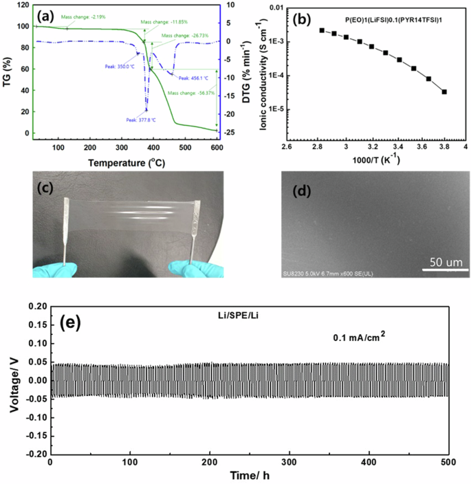
a Thermogravimetric and differential thermogravimetric (TG–DTG) analysis results, b ionic conductivity, c photograph, and d surface morphology of cross-linked PEO–LiFSI0.1(Pyr14TFSI)0.4 SPE. e Li plating/stripping curve of Li//Li symmetric cells with dual-anion PE at 0.1 mA/cm.
To investigate the stability of the Li metal anodes in the dual-anion SPE, the voltage variation of symmetric Li//Li cells was assessed during galvanostatic cycling at a constant current of 0.1 mA/cm2 (Fig. 5e). The Li/SPE/Li cell delivered a stable voltage hysteresis of 50 mV with no oscillation throughout 500 h of cycling, indicating dendrite-free Li deposition with the dual-anion SPE. The linear sweep voltammetry curve, which was used to investigate the SPE anodic stability, is presented in Fig. S4. The curve was straight, and the steady voltage reached 4.43 V (vs. Li/Li + ) at a 0.1 mV s−1 scan-rate. This result indicates that the SPE was undecomposed at 4.4 V, which is almost identical to the behavior observed for the original liquid electrolyte (4.4 V). Thus, dual-anion SPEs are suitable for application in conventional LIBs.
Figure 6 shows the electrochemical characterization results for the integrated ASS Li–S battery in the 1.7–2.8 V potential range. The typical charge–discharge profile (Fig. 6a) of the Li–S battery displayed two discharge potential plateaus, which corresponded to the two-step reaction of S during the discharge process. The first plateau near the 2.3 V region was related to the long-chain polysulfides (Li2Sx, x ≥ 4.4) produced by the continuous reduction in elemental S owing to the low discharge capacity53. The second plateau, at a voltage below 2.1 V, was caused by the conversion of short-chain polysulfides (Li2S2 or Li2S), which provided most of the discharge capacity ( ~ 75%)13,15. The S/rGO-based integrated ASS Li–S battery exhibited an initial discharge capacity of 957 mAh g−1. The 100th-cycle discharge capacity was considerably reduced with cycling at 0.1 C. Figure 6b shows the rate performance of the S/rGO-based integrated Li–S battery in the potential range of 1.7–2.8 V at current densities of 0.1–2 C. The discharge voltage was decreased to 1.7 V because lower voltages could lead to irreversible decomposition of the electrolyte salt; thus, measurements were not taken at voltages lower than this value. Additionally, such irreversible decomposition of the electrolyte salt affects the electrochemical performance of the battery. The reversible capacities of the S/rGO-based ASS Li–S battery were 957, 777, 631, 421, and 188 mAh g−1 at constant current rates of 0.1, 0.2, 0.5, 1, and 2 C, respectively, with a rate capability of 44% (1 C/0.1 C). Figure 6c, d show the cycling performance of the S/rGO-based integrated ASS Li–S battery at 0.1 and 1 C, respectively. The discharge capacities at both C rates markedly decreased in the initial five cycles but subsequently remained relatively stable. This rapid capacity reduction was due to initial structural stabilization. Additionally, the discharge capacities at both C rates were significantly lower than the theoretical capacity (1675 mAh g−1) of lithium‒sulfur batteries. The reason for the failure of the initial discharge capacity to meet expectations may be that the solid electrolyte only contacted the cathode active substance at the interface, increasing the transport path of lithium ions; thus, the active sulfur was not fully utilized. The cycle retention rate calculated from the 5th to 100th cycles at 0.1 C was approximately 72%. However, at 1 C, the discharge capacity retention was 87% (calculated from the 5th cycle) until the 100th cycle, and this capacity was maintained at 82% (calculated from the 5th cycle) until the 200th cycle. Thus, the S/rGO-based integrated ASS Li–S battery exhibited enhanced high-rate stability.

a Charge–discharge curves, b rate performance, and cycle performance of S/rGO-based integrated Li–S batteries in the potential range of 1.7–2.8 V at c 0.1 C and d 1 C.
The S/rGO-based integrated solid-state Li–S batteries delivered stable cycling performance over 100 cycles because of the presence of the SPE (PEO–LiFSI0.1(Pyr14TFSI)0.4). This finding indicates that the SPE layer effectively suppressed dendritic Li formation54. To further investigate the cycling behavior, the Li morphologies of the batteries were examined via ex situ SEM analysis. The Li-metal electrode exhibited high dendritic growth (Fig. 7a). In contrast, the Li electrode combined with the SPE exhibited a well-preserved surface with a slightly wrinkled morphology (Fig. 7b). These results confirm that the SPE combination layer effectively suppressed the formation of Li dendrites.

Ex-situ SEM images of Li electrodes with a liquid electrolyte and b SPE after the 100th cycle.
The results were compared with those recently reported for other SPE-based Li–S batteries (Table 1). Most current SPEs exhibit ionic conductivities of ~10−4 S cm−1 at room temperature36,37,38,39,40,41,43,44,55,56. Moreover, most charging/discharging tests are conducted at low C rates (0.05–0.2 C) for up to 100 cycles. In a previous study, an integrated ASS Li–S battery using S/graphene and an LPS–PEO–LiClO4 SPE exhibited an initial discharge capacity of 826 mAh g−1 with a cycle retention of 48% for up to 60 cycles at 0.05 C36. Furthermore, ASS Li–S batteries incorporating CMK-3/S and LiTNFSI/PEO SPE demonstrated an initial discharge capacity of 600 mAh g−1 and cycle retention of 67% (200 cycles)40. However, the capacity and cycle retention of the ASS Li–S battery with the integrated electrode proposed in this study surpassed those of previously reported ASS Li–S batteries36,37,38,39,40,41,43,44,55,56. Moreover, this performance withstood up to 200 cycles, even at 1 C. Therefore, PEO–LiFSI combined with Pyr14TFSI enhances the high-speed stability of S/rGO-based integrated ASS Li–S batteries.
Figure 8 shows a high-resolution S 2p spectrum obtained for the S/rGO-integrated cathode after 100 charge/discharge cycles. The binding energies of the electrochemically reacted S species were in the range of 160–165 eV. The peaks at 160.5/161.4, 161.6/162.3, and 162.7/164.1 eV were assigned to the S2− ion of Li2S, terminal S1− of Li2Sx (x = 2–6), and S0 of the bridging S, respectively. The S 2p spectrum exhibited a peak at 169.1/170.5 eV, corresponding to the sulfone groups (R-SO2-R) of TFSI and FSI on the electrode surface57. This spectrum also had two peaks at 167.6/168.5 eV, which were assigned to the formed sulfite or thiosulfate species on the electrode surface58. After delithiation, the peaks corresponding to Li2Sx and Li2S remained in the spectrum of the cycled S/rGO electrode, indicating that some lithiated Li polysulfide species no longer participated in the electrochemical reaction; this caused capacity loss in the LSBs. The peak S2−, S1−, and S0 concentration ratios were 21%, 20%, and 59%, respectively, and the S0 ratio was equal to the capacity retention after 100 cycles. Although lithiated Li polysulfides were discovered on the S/rGO integrated cathode, their concentration was lower than that reported in previous studies57,58,59. The low Li polysulfide ratio in the cathode was probably caused by the high reversible reactivity of the S/rGO electrode and the inhibition of polysulfide shuttling by the SPE (PEO–LiFSI0.1(Pyr14TFSI)0.4).

XPS analysis results for the S/rGO integrated electrode after 100 cycles.
Finally, a flexible integrated ASS Li–S battery composed of an integrated S/rGO/PE cathode and SPE was prepared. This flexible battery exhibited good performance in a bent state with a radius of curvature R of 50 mm (Fig. S5). Fig. S6 shows the cycling properties of the flexible S/rGO-based integrated solid-state Li–S batteries in the bent (R = 50 and 10 mm) and flat states (R = 0). The discharge capacity was 732.3 mAh g−1 even after 10 cycles of R = 50 mm bending, whereas it was 751.5 mAh g−1 before bending. The discharge capacity reached 600 mAh g−1 for R = 10 mm bending. Although the capacity was reduced by 20% at R = 10 mm, a high capacity was maintained, even in the bent state. In addition, the capacity recovered to 696.1 mAh g−1 when the integrated Li–S cell was reflattened. In commercial LIBs, bending can cause delamination or cracking–swelling of the electrode or membrane, resulting in a rapid capacity drop. However, even after bending, the capacity of the flexible S/rGO-integrated ASS Li–S battery did not decrease significantly. Therefore, the dual-anion SPE and S/rGO/PE-integrated cathode effectively improve the safety and electrochemical performance of Li-S batteries.
Conclusions
This study presents the successful preparation of a functionalized rGO cathode with well-dispersed S particles via a hydrothermal reaction. Furthermore, a crosslinked PEO–LiFSI0.1(Pyr14TFSI)0.4 SPE film was fabricated as an integrated electrode, serving as both the cathode and electrolyte, by bonding with the S/rGO/PE integrated cathode, and it was used in an integrated ASS Li–S battery. PE was used instead of the binder in the S/rGO-integrated cathode. The homogenous compact contact between S/rGO and the SPE improved the electrochemical performance. Consequently, the ASS Li–S battery exhibited a reversible capacity of 417 mAh g−1 with a capacity retention of 71% after 200 cycles at 1 C. Moreover, the SPE (PEO–LiFSI0.1(Pyr14TFSI)0.4) and S/rGO-based solid-state Li–S batteries exhibited more stable performances than the Li–S batteries using liquid electrolytes, as the shuttle effect was suppressed and lithium dendritic formation was inhibited. Therefore, the proposed S/rGO/PE electrode and crosslinked PEO–LiFSI0.1(Pyr14TFSI)0.4 SPE could be used to improve the electrochemical properties of Li–S batteries. Furthermore, the S/rGO/PE/PEO–LiFSI0.1(Pyr14TFSI)0.4 integrated electrode has a long lifecycle and is safe to operate; therefore, it can be applied to mid-to-large batteries capable of fast charging for large-scale applications.


Responses