Unconventional nonlinear Hall effects in twisted multilayer 2D materials

Introduction
Nonlinear optical phenomena in two-dimensional (2D) materials have garnered significant attention due to their potential applications in next-generation optoelectronic and photonic devices1,2,3,4. Among these materials, hexagonal boron nitride (h-BN), with its wide band gap and robust mechanical properties, has emerged as a promising platform for investigating new physical phenomena and enhancing device functionalities5,6,7,8,9. A particularly unique property in these materials is the nonlinear Hall effect, typically a second-order transverse response driven by the Berry curvature dipole in non-centrosymmetric non-magnetic systems10,11,12,13,14. This effect has been extensively documented in monolayers and simple bilayers, yet its complexity significantly increases with additional stacking configurations15,16,17,18,19,20,21,22,23.
Recent advancements have shown that multilayer configurations of 2D materials exhibit unique electronic and optical properties that are not merely extensions of their monolayer counterparts24,25,26,27,28,29. Specifically, the interaction between layers and the resulting modification of physical properties due to stacking configurations offer a rich landscape for the exploration of novel phenomena, such as superconducting flat bands in bilayer graphene with Moire patterns, induction of spin-orbit coupling, and controllable film growth mechanisms30,31,32,33. However, conventional theories that describe the nonlinear Hall effect based on the total Berry curvature dipole are insufficient for multilayer structures where interlayer dynamics significantly influence the overall effect.
This study examines the unusual and unexpected behavior of the nonlinear Hall effect within stacked multilayer structures. Our results show that beyond the conventional Berry curvature dipole model, the stacking order and interlayer interactions are crucial in dictating the nonlinear optical responses of these systems. Using state-of-the-art theoretical methods, including Real-Time Time-Dependent Density Functional Theory (RT-TDDFT)34,35,36,37, model Hamiltonian approaches, and symmetry analysis, we dissect the contributions of interlayer interactions and uncover the underlying mechanisms of the nonlinear Hall effect in h-BN multilayers. In contrast to traditional approaches, our results show a unique second-harmonic transverse response in twisted h-BN four-layers despite the nullification of the overall Berry curvature. We observe distinct nonlinear optical properties due to different chiral stacking configurations and propose a novel method to control optical responses using directional torsion forces. Our investigation challenges the prevailing understanding of the topological origin of the optical nonlinear Hall responses in layered materials and opens new avenues for the design and development of advanced materials with tailored optical properties.
Results
Theory and construction of twisted h-BN multilayers
The relationship between the nonlinear Hall response of insulators and their Berry curvatures was recently explored by one of us11. In this previous study, the main contribution to the second-harmonic Hall current density ({{boldsymbol{J}}}_{perp }^{2omega }) of a non-centrosymmetric insulator to an applied electric field E with frequency ω was found to be proportional to the Berry curvature dipole as
where e is the charge of an electron, (hat{{boldsymbol{z}}}) is the normal unit vector of the 2D material surface, and ({f}_{n{boldsymbol{k}}}) are the band occupation factors. ({{boldsymbol{D}}}_{{nm}}) are the interband Berry curvature dipole matrix elements between band n and band m, defined as
where ({int }_{{boldsymbol{k}}}equiv int frac{{d}^{2}{boldsymbol{k}}}{4{pi }^{2}}) represents the 2D Brillouin zone integration, fnk are the band occupation factors, ({omega }_{{mn}}=left[{varepsilon }_{m}left({boldsymbol{k}}right)-{varepsilon }_{n}left({boldsymbol{k}}right)right]/hslash) is the energy-level difference between the ground state eigenstates |ψm(k)〉 and |ψn(k)〉 at a crystal momentum point k, Θ is the Heaviside step function, and ({varOmega }_{{nm}}) is the interband Berry curvature11 given by
where ({v}_{{nm}}^{y}) and ({v}_{{nm}}^{x}) are the y– and x-components of the dipole matrix elements (leftlangle {psi }_{n}left({boldsymbol{k}}right)|hat{{boldsymbol{p}}}|{psi }_{m}left({boldsymbol{k}}right)rightrangle), respectively, where (hat{{boldsymbol{p}}}) denotes the momentum operator.
Using the identity between the total interband and total single-band Berry curvatures (sum _{{nm}}{f}_{n{boldsymbol{k}}}left(1-{f}_{m{boldsymbol{k}}}right){Omega }_{{nm}}=sum _{n}{f}_{n{boldsymbol{k}}}{Omega }_{n}), where the single-band Berry curvature is ({Omega }_{n}left({boldsymbol{k}}right)=2cdot{text{Im}}{sum}_{mne n}{v}_{{nm}}^{y}{v}_{{mn}}^{x}/{omega}_{{mn}}^{2}), we obtain the following qualitative relationship
where the integration is performed over the area enclosed by (varTheta left(2omega -{omega }_{{vc}}right)), and the bandgap of the system is the energy separation between v (valence band maximum, VBM) and c (conduction band minimum, CBM). The integration area in Eq. (2) is determined separately for n–m band pairs, and, thus, Eq. (4) can have fewer or more terms than Eq. (1). However, our approximation in Eq. (4) is valid since the main contribution to the Berry curvature arises from VBM and CBM bands11. The term “Berry curvature” represents the total single-band Berry curvature hereafter.
We argue that the second-harmonic Hall current of two distinct systems, whose band structures are very similar and momentum-resolved Berry curvatures are proportional to each other, can directly be compared by their total Berry curvatures at any arbitrary ({boldsymbol{k}}) point:
This argument holds for some special cases, such as homogenous Van der Waals multilayer structures whose Berry curvatures are summative/additive. In these structures, comparing the Berry curvature at an arbitrary ({boldsymbol{k}}) point is enough to compare their integrated Berry curvature. From this approximation, we comprehensively include the contributions of higher-order Berry curvature multipoles38 with the dipole, as their magnitudes are also proportional to the magnitude of the Berry curvature.
We found that the use of Eq. (5) is suitable for the description of the 2D systems in this work11. Therefore, we analyze the second-harmonic Hall response of twisted h-BN multilayers under a linearly polarized laser field with nearly half the bandgap frequency that maximizes the transverse second-harmonic generation (see Fig. 1). Each layer exhibits a second-harmonic response in the transverse direction (gray arrows in Fig. 1) depending on its Berry curvature component that connects the directions of the field and its response. For instance, we calculate ({Omega }^{{xy}}) since the applied field is polarized in the x-direction and the corresponding response is polarized in the y-direction.

The yellow arrows in the figure and the inset represent the applied laser pulse polarized in the x-direction. The pulse frequency ω is slightly larger than half the bandgap. The gray arrows on the h-BN layers depict the transverse second-harmonic generation in the y-direction.
To construct the twisted h-BN multilayers, we first define the twist angle and possible monolayers in the supercell of the corresponding twist angle. The smallest twisted supercell for a hexagonal unit cell is a (sqrt{7}times sqrt{7}) supercell that corresponds to a 21.8° twist angle39,40 (see Methods for further details on geometry optimizations and other calculation parameters). There are four possible configurations of a h-BN monolayer on a (sqrt{7}times sqrt{7}) supercell: A, A’, B, and B’, as shown in Fig. 2. Configurations A and B are inversion pairs such that B can be obtained by an inversion transformation of A or simply by flipping the position of boron and nitrogen bases. This transformation also flips the sign of the Berry curvature. Thus, if the Berry curvature of A at a certain ({boldsymbol{k}}) point is (Omega), it is (-Omega) for B. Similarly, A’ and B’ configurations are obtained by mirror reflection of A and B with respect to the yz-plane. This reflection also results in a flip in the sign of the Berry curvatures. On the other hand, A-B’ and A’-B are reflection pairs with respect to the xz-plane and have Berry curvatures with the same sign. Therefore, the Berry curvature of configurations A and B’ is (Omega), whereas it is (-Omega) for A’ and B (see Fig. 2). The three-fold symmetry of the individual h-BN layers dictates three identical Berry curvature dipoles, ({{boldsymbol{D}}}_{{nm}}), with a 120° angle separation, resulting in the cancellation of the Berry curvature contribution to the second-harmonic Hall effect, as can be obtained from summation of ({{boldsymbol{D}}}_{{nm}}) along different directions through Eq. (1). However, in this study, we focus on stacked multilayers that do not preserve three-fold symmetry. Therefore, the Berry curvatures of individual layers contribute without cancellation to the system’s total Berry curvature dipole.

We label four possible configurations as A, A’, B, and B’. These configurations are connected with mirror and inversion symmetries: A-A’ and B-B’ are mirror pairs, and A-B and A’-B’ are inversion pairs. Accordingly, the Berry curvature of each configuration has an opposite sign with a symmetry pair.
We investigated whether a specific stacking order of twisted layers can bring unusual phenomena, such as chirality-dependent optical effects41,42, chiral-torsion effects43, or torsion-induced transport44. For this purpose, we prepared clockwise-twisted (CW-twisted) and counterclockwise-twisted (CC-twisted) multilayers separated by a ~ 3.5 Å distance. Since none of the allowed twist angles for constructing a moiré lattice are integer multiples that can divide 120˚, it is impossible to achieve uniformly twisted multilayers39. However, we can mimic CW- and CC-twisted structures with AA’BB’ and AB’BA’ stacking, as seen in Fig. 3. In this case, the twist angle between the 1st and 2nd layers in the CW-twisted ordering (A and A’) is 21.8˚, whereas it is 38.2° between the 2nd and 3rd layers (A’ and B). Even though we cannot obtain a uniform twisting between neighboring layers due to a non-integer twist angle, alternating stacking of layers with a 30˚ ± 8.2° angle would effectively produce twisted structures.
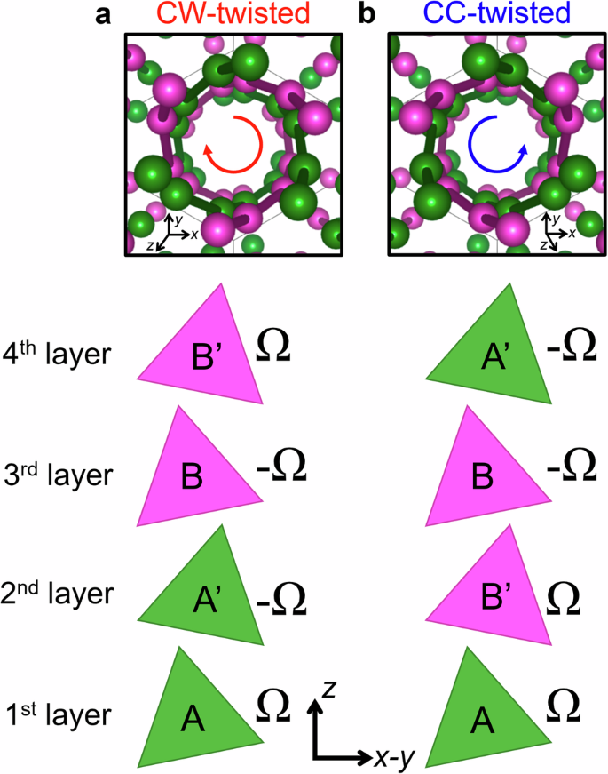
The upper panels of (a) and (b) are top views of clockwise- and counterclockwise-twisted (abbreviated as CW- and CC-twisted) h-BN multilayers, respectively. The lower panels show the corresponding out-of-plane layer ordering up to the fourth layer and the Berry curvature of each layer in the twisted multilayers.
Berry curvature and second-order optical responses of twisted h-BN multilayers
We compare the total Berry curvatures and second-harmonic Hall responses for monolayer, bilayers, 3-layers, and 4-layers of CW- and CC-twisted stackings of h-BN. This comparison allows us to assess whether (1) the Berry curvature of multilayers is additive, (2) twisted stackings provide novel phenomena, and (3) real-time current responses maintain the quantized behavior of the Berry curvature.
The momentum-resolved total Berry curvatures of the 1- to 4-layer structures are given in Fig. 4. We denote the Berry curvature of the monolayer (configuration A) at the ({boldsymbol{k}}=K) point as (varOmega) (see black dashed line in Fig. 4a) and compare the Berry curvatures at the same ({boldsymbol{k}})-point for the other multilayers. The additive behavior of the Berry curvature can be observed in Fig. 4b, c. The stacking in the CW- and CC-twisted systems are (A, A’, B, B’) and (A, B’, B, A’), and their Berry curvatures are (left(Omega ,,-Omega ,,-Omega ,,Omega right)) and (left(Omega ,,Omega ,,-Omega ,,-Omega right)), respectively. The summation of the individual Berry curvatures of mono-, bi-, 3-, and 4-layers of CW- and CC-twisted stackings are (left(Omega ,,Omega -Omega ,,Omega -Omega -Omega ,,Omega -Omega -Omega +Omega right)=left(Omega ,,0,,-Omega ,,0right)) and (left(Omega ,,Omega +Omega ,,Omega +Omega -Omega ,,Omega +Omega -Omega -Omega right)=left(Omega ,,2Omega ,,Omega ,,0right)), respectively. As seen in Fig. 4b, c, the calculated total Berry curvatures of the multilayers show the exact same values. Therefore, we can conclude that the Berry curvature of h-BN multilayers is summative; i.e., the total Berry curvature of the system is the summation of each layer’s Berry curvature.

The total Berry curvature of a h-BN monolayer as a function of momentum vector, ({boldsymbol{k}}), is shown in panel a. The monolayer is constructed on a (sqrt{7}times sqrt{7}) supercell with configuration A. The left, middle, and right sub-plots in panel (b) are total Berry curvatures of the left-handed bilayer (AA’), 3-layers (AA’B), and 4-layers (AA’BB’), respectively. Panel (c) is the same for the right-handed bilayer (AB’), 3-layers (AB’B), and 4-layers (AB’BA’), respectively. The insets in the right panels of (b) and (c) are the top views of left- and right-handed multilayers, respectively.
To compare the Berry curvatures obtained from the ground-state wavefunctions with real-time excited-state responses, we carried out RT-TDDFT calculations that explicitly propagate the excited-state wavefunctions in real time36. The Kohn–Sham (KS) wavefunctions |ψnk(r,t)〉 are propagated via the time-dependent KS equation as follows:
where the second and third terms within the brackets are the atomic pseudopotential and Hartree-exchange-correlation potential, respectively. ({m}_{e}) is the electron mass, (c) is the speed of light, and the vector potential ({boldsymbol{A}}left(tright)=-c{int }_{0}^{t}dtau {boldsymbol{E}}left(tau right)) corresponds to the electric field component of the applied laser, ({boldsymbol{E}}left(tright)), which is polarized in the x-direction (see the upper panel of Fig. 5a) according to:
where the laser strength and frequency is set to ({E}_{0}=0.01,{text{V}}/{text{AA}}) and ({omega}_{0}=0.65{varepsilon}_{text{gap}}) (where εgap is the DFT-computed bandgap), respectively, to maximize the nonlinear Hall response11. The details of our RT-TDDFT computations are provided in Methods. The cell-averaged transverse current density can be calculated from the velocity expectation value of the time-evolving KS wavefunctions:
where L is the average length of the 2D unit cell in the y-direction. The mechanical momentum operator in the velocity gauge is given by ({hat{pi }}_{y}={hat{p}}_{y}+frac{m}{ihslash }[{r}_{y},{hat{V}}_{text{NL}}]), where ({hat{V}}_{text{NL}}) is the nonlocal part of the pseudopotential45. To minimize the numeric noise of the time evolution, we subtract the current response with ({boldsymbol{A}}left(tright)=0) from the current response with the applied laser vector potential. Furthermore, to obtain a pure second-order response without odd-order contributions, we also calculate the response with (-{boldsymbol{A}}left(tright)) and add it to the response with ({boldsymbol{A}}left(tright)) (see Methods for more details).

The upper and lower sub-plots in panel (a) are the real-time profiles of the applied laser field current density response, respectively, of the h-BN monolayer. The left, middle, and right sub-plots in panel (b) are the current density responses of the left-handed bilayer (AA’), 3-layers (AA’B), and 4-layers (AA’BB’), respectively. Panel c is the same for the right-handed bilayer (AB’), 3-layers (AB’B), and 4-layers (AB’BA’), respectively. The same units are used for all current responses. Panels (d, e, and f) are Fourier transforms of the monolayer, CW-twisted multilayers, and CC-twisted multilayers, respectively.
Taking the current density response of the monolayer in Fig. 5a as a reference, we observe that the bilayers in the left panels of Fig. 5b, c are consistent with the corresponding Berry curvatures presented in the left panels of Fig. 4b, c. The CW-twisted bilayer shows no response, while the CC-twisted bilayer exhibits an enhanced response even if it is not ideally twice the monolayer response. The real-time dynamics of 3-layers are also consistent with the corresponding Berry curvatures: (Omega) and (-Omega) for CW- and CC-twisted 3-layers, respectively. The real-time responses of the CW- and CC-twisted structures have opposite signs, as seen in the insets of the middle panels of Fig. 5b, c. Moreover, the magnitude of the current responses of 3-layer structures is similar to one of the monolayers (Fig. 5a). The average amplitudes and frequencies of the observed responses are presented in Fig. 5d–f. The CC-twisted bilayer exhibits a response with an amplitude approximately twice that of the monolayer and the 3-layer system. On the other hand, all non-zero responses show only the 2({omega }_{0}) frequency component, indicating that the obtained responses correspond exclusively to second-order Hall currents.
The CW- and CC-twisted stackings are different in terms of the evolution of the Berry curvature. However, these are natural outcomes of the summative behavior and are not unique to chiral ordering. Chiral structures are usually incorporated with magnetic effects such as chirality-induced spin selectivity46,47. Since we only consider pure electron dynamics associated with the stacking of the structures without considering the spin degree of freedom nor explicitly including magnetic effects, it is expected that we do not reproduce any chirality-induced phenomena. Nevertheless, the distinct nonlinear responses depending on twisting direction suggest a novel engineering application: CW- and CC-twisted multilayers can be switched by applying an opposite torsional force to the slab structure. For instance, the nonlinear signal in the bilayer structure can be turned on and off only by rotating the layers in the opposite direction in the xy-plane by a torsion force. Similarly, the sign of the signals in 3 layers can be switched by the same structural manipulation. Collectively, these approaches introduce a new, previously unexplored technique for adjusting optical responses by applying directional torsion forces to these systems.
The situation is dramatically different for the 4-layer structures. The CW- and CC-twisted 4-layers have zero Berry curvature over the Brillouin zone. Thus, one can expect no second-harmonic Hall current in these structures. However, as shown in the right panel of Fig. 5b, the CW-twisted 4-layer exhibits a significant response comparable to the CC-twisted bilayer with a (2Omega) Berry curvature. Since this response is unexpected based on the traditional understanding, we designate this as an “unconventional nonlinear Hall effect”.
Discussion
To understand and classify the unconventional Hall response observed in the CW-twisted 4-layer structure (Fig. 5b), we extend our analysis to various stacking orders of 4-layers. As seen in Fig. 6a, we start from the (A, B’, B, A’) structure with Berry curvatures of (left(Omega ,,Omega ,,-Omega ,,-Omega right)). In this case, the total Berry curvature and the current density response are zero. When we do a cyclic permutation by bringing the top layer under the bottom one (as seen in Fig. 6b), the stacking and corresponding Berry curvature become (A’, A, B’, B) and (left(-Omega ,,Omega ,,Omega ,,-Omega right)), respectively. Even though the total Berry curvature is still zero and the same layers are used, the system now has a non-zero real-time response after a slight change in the layer ordering.

The upper panels illustrate the out-of-plane layer orderings for various 4-layer structures. The middle and lower panels are the momentum-resolved Berry curvatures and the real-time current density responses of the corresponding structures, respectively. Panel (a) shows AB’BA stacking, which is also shown in Figs. 3c and 4c. Configuration (b) is obtained by placing the top A’ layer of panel (a) on the bottom. Configuration c (d) is obtained by interchanging the middle (bottom) two layers of configuration b (c).
Next, we test the stacking order obtained by switching the 2nd and 3rd layers of the last structure (see Fig. 6c). The stacking is now (A’, B’, A, B), and the corresponding Berry curvatures are not affected by this transformation as the inner two layers have the same Berry curvature: (left(-Omega ,,Omega ,,Omega ,,-Omega right)). By flipping the layers, we break the twistedness of the structure, which cannot be formed by a directional torsion force, but keep the ordering of Berry curvatures. The resultant real-time response is the same as the previous structure. Thus, we conclude that the unconventional Hall effect occurs regardless of special geometric ordering. Instead, the observed phenomenon appears to be related to the order of the Berry curvatures of the layers.
Lastly, we flip the 1st and 2nd layer of the previous structure and obtain the stacking (B’, A’, A, B) with the Berry curvature ordering (left(Omega ,,-Omega ,,Omega ,,-Omega right)) (see Fig. 6d). Now, the Berry curvature order has been changed, and the system shows no real-time response.
The 4-layer structures with the Berry curvature ordering of (left(Omega ,,Omega ,,-Omega ,,-Omega right)) and (left(Omega ,,-Omega ,,Omega ,,-Omega right)) have no response that is consistent with the total Berry curvature. When the layers are ordered in such a way that their Berry curvatures are (left(-Omega ,,Omega ,,Omega ,,-Omega right)), we observe an unconventional nonlinear Hall effect. The common property of the former two structures is that they have an odd-symmetry Berry curvature (with respect to the center of the system) in the z-direction. However, the latter ordering has an even symmetry in the z-direction. The system must be non-centrosymmetric to observe the Hall effect as the Berry curvature vanishes in the presence of an inversion center. Even though all our twisted 4-layers are non-centrosymmetric and have zero Berry curvature, the presence of odd-ordered Berry curvature is a secondary requirement to suppress the Hall effect. On the other hand, the presence of an even-ordered Berry curvature allows an unexpected Hall effect. If the layers were completely non-interacting, then each layer’s nonlinear transverse current response would independently obey its own Berry curvature, and the total response would be zero for any system in Fig. 6. Consequently, the interlayer interactions have some crucial role in the observation of these non-zero responses.
To explore the role of the interlayer interactions in second-harmonic Hall responses, we carried out RT-TDDFT calculations for BBAA and BAAB 4-layers with various separations whose Berry curvatures are (left(-Omega ,,-Omega ,,Omega ,,Omega right)) and (left(-Omega ,,Omega ,,Omega ,,-Omega right)), respectively (see Fig. 7a, d). When the interlayer separation distance is set to d = 10 Å, the layers are non-interacting, and as seen in Fig. 7b, e, produce negligible responses. However, when the layers are separated by the geometry-optimized distance of d = 3.5 Å, a nonlinear Hall response is obtained for BAAB stacking. The responses shown in Fig. 7c, f are similar to Fig. 6a, b, which have different stacking but the same Berry curvature ordering with the BBAA and BAAB stackings, respectively. This result proves that the origin of the unconventional Hall effect observed in Figs. 5b, 6b, 6c, and 7f is the interlayer interaction, and the effect disappears when the layers are not interacting.

a The BBAA stacking geometry, where d denotes the interlayer distance. Panels (b) and (c) show the corresponding RT-TDDFT current density response when d = 10 and 3.5 Å, respectively. Panels (d–f) are the same as panels (a–c) for BAAB stacking.
To further analyze the interlayer interactions, we constructed 8 × 8 model Hamiltonians that mimic BBAA and BAAB stackings (see Fig. 8a, g). For simplicity, we consider only A and B layers with two basis atoms per layer in the unit cell instead of twisted layers with fourteen basis atoms in the (sqrt{7}times sqrt{7}) supercell. Even though the BBAA stacking is centrosymmetric and is expected to not exhibit the Hall effect, it is used here as a representative system with odd-ordered Berry curvature. We adopt the BAAB stacking to reveal the role of interlayer interactions in the unconventional Hall effect in structures with an even-ordered Berry curvature.
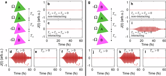
a The BBAA stacking geometry, where the interlayer hopping parameters between 1st-2nd, 2nd-3rd, and 3rd-4th layers are T12, T23, and T34, respectively. Panels (b–f) are the transverse current densities obtained from the model Hamiltonian calculations with the interlayer interactions as follows: (b) no interaction: T12 = T23 = T34 = 0; (c) full interaction: T12 = T23 = T34 > 0; (d) only the bottom two layers interact: T12 > 0, T23 = T34 = 0; (e) only the middle two layers interact: T23 > 0, T12 = T34 = 0; and (f) only top two layers interact: T34 > 0, T12 = T23 = 0. Panels (g–l) are the same as panels (a–f) for BAAB stacking.
The minimal model Hamiltonian in momentum space for the 4-layer structures can be constructed as follows:
where mi is the mass term originating from the on-site energy difference between boron and nitrogen basis atoms at the ith layer, which is set to ({m}_{i}=m=2.73,text{eV}) if the ith layer has a B configuration, and ({m}_{i}=-m) if it has an A configuration. The (f={t}_{H}left({e}^{i{boldsymbol{k}}{cdot}{{boldsymbol{tau }}}_{1}}+{e}^{i{boldsymbol{k}}{cdot}{{boldsymbol{tau }}}_{2}}+{e}^{i{boldsymbol{k}}{cdot}{{boldsymbol{tau }}}_{3}}right)) term models the intralayer hopping between nearest-neighbor atoms, where ({t}_{H}=2.00,text{eV}) is the intralayer hopping integral, and ({{boldsymbol{tau }}}_{i}) are the vectors connecting a chosen atom with its three neighboring atoms in the same layer in the hexagonal unit cell. As shown above, ({T}_{i,i+1}={T}_text{H}{e}^{i{boldsymbol{k}}{cdot}{boldsymbol{c}}}) is the interlayer hopping between nearest-neighbor atoms in the ith and (i + 1)th layer, where ({T}_text{H}=1.00,text{eV}) is the interlayer hopping integral, and ({boldsymbol{c}}) is a vector in the z-direction connecting a chosen atom with its vertical neighbor in the upper layer. Here, we assume only a nearest-neighbor interaction, and thus, the hopping occurs between the same (different) type of atoms for AA and BB (AB and BA) stacked neighboring layers. The magnitude of TH is inversely proportional to the interlayer distance d such that larger interlayer distances correspond to smaller interlayer hopping strengths (and vice versa). Similar to Eq. (6), we solve the time-dependent model Hamiltonian equation given by (ihslash frac{partial }{partial t}left|{psi }_{n}left(boldsymbol{k},tright)rightrangle =hat{H}left({boldsymbol{k}}-frac{e}{c}{boldsymbol{A}}left(tright)right)left|{psi }_{n}left(boldsymbol{k},tright)rightrangle) with the same field described in Eq. (7).
When the interlayer hopping interaction is not included, there is no transverse response regardless of stacking order, as seen in Fig. 8b, h. However, only BAAB stacking has a finite response when the interlayer interactions are turned on (see Fig. 8c, i), as observed in our RT-TDDFT calculations in Fig. 7c, f. To fully understand this effect, we analyze pairwise interlayer interactions. The interlayer distance is approximately 3.5 Å, and next-nearest layer interactions can be safely neglected. Thus, we can examine the nearest-neighbor layer pairs by adjusting the parameters T12, T23, and T34.
As shown in Fig. 5b, c, bilayers with the same Berry curvatures exhibit a Hall response, while those with opposite Berry curvatures do not. Taking this into account, we can turn on the hopping between the BB layer pair in the BBAA stacking (T12 > 0, T23 = T34 = 0) and obtain a non-zero response (see Fig. 8d) as expected from Fig. 5c. This response solely originates from the interlayer coupling of the 1st and 2nd layers since the summation of the individual layers’ responses is zero as shown in Fig. 8c. Next, we can turn on the hopping between the BA layer pair only (T23 > 0, T12 = T34 = 0) and observe a zero response (see Fig. 8e) as expected from Fig. 5b. Lastly, when the hopping is allowed between only the AA layer pair (T34 > 0, T12 = T23 = 0) (see Fig. 8f), we obtain the exact opposite response of the case with hopping between only the BB layer pair. This is a reasonable result since the B and A layers have opposite Berry curvatures, and these individual responses can be considered as contributions of each layer pair to the total response of the entire interacting system. Thus, the contributions from the BB pair and AA pair cancel each other. Since the BA pair has no contribution, the resultant total response becomes zero, as obtained in Fig. 8c. We repeat the same analysis for the BAAB stacking and obtain zero response when the BA or AB layer pairs are interacting (see Fig. 8j, l, which are same as Fig. 8e). In comparison, a finite response is obtained when the AA layer pair is coupled (see Fig. 8k, which is the same as Fig. 8f). Since there is no other pair that can cancel the contribution of the AA pair, the fully-interacting BAAB structure also has a finite transverse response, which we previously designated as an unconventional nonlinear Hall effect. The same pairwise analysis can explain the responses obtained in Figs. 5 and 6 for the bi-, 3-, and 4-layer structures.
Our model Hamiltonian analysis in Fig. 8 shows that the unconventional Hall response originates from interlayer hopping between neighboring layers with the same Berry curvatures. Specifically, when two layers with opposite Berry curvatures interact, the electrons tend to move in opposite transverse directions, and upon hopping, they encounter an opposing current contribution, which cancels out any net transverse current. In contrast, when layers with the same Berry curvature interact, the electrons move in the same transverse direction, and upon hopping, they contribute to the same current direction, generating a net transverse current. This cooperative interaction explains why only layers with aligned Berry curvatures contribute to the unconventional Hall response. Additionally, we assume that the dominant interactions are between nearest-neighbor layers, effectively treating them as bilayers, while next-nearest-neighbor interactions are negligible. In conclusion, the Hall response in the system arises from both the additive Berry curvatures of individual layers and the enhanced contribution from interacting bilayer pairs with aligned Berry curvatures, which together produce the observed responses in the multilayer systems.
The semi-classical approach explained above can be attributed to the higher-order contributions of the interband Berry curvature between bands of nearest-neighbor layers. However, our results indicate that those contributions do not originate from Berry curvature multipoles as they are proportional to the Berry curvature38. One of us previously defined a three-band term that contributes to this response but did not show any physical connection between this term and the Berry curvature11. Our findings in this work now provide a qualitative mechanistic relationship between the three-band term and Berry curvature through these interlayer interactions.
We extended our analysis to 6-layer systems to understand the role of interlayer interactions in the unconventional Hall effect (see Fig. 9). Similar to the 4-layer systems, we obtain finite contributions from neighboring layers with the same Berry curvatures (Fig. 9d, f, l), whereas the interaction between layers with opposite Berry curvatures does not generate a transverse response (Fig. 9c, e, i–k). Also, the AA and BB pairs induce responses in opposite directions (Fig. 9d, f). Thus, the ABBAAB stacking has no net response (Fig. 9b), whereas ABABBA stacking exhibits a net Hall current due to the BB layer pair (Fig. 9h).

a ABBAAB stacking geometry, where the interlayer hopping parameters between the 1st-2nd, 2nd-3rd, 3rd-4th, 4th-5th and 5th-6th layers are T12, T23, T34, T45, and T56, respectively. Panels (b–f) depict the transverse current densities obtained from the model Hamiltonian calculations with the interlayer interactions as follows: (b) all neighboring layers are interacting: T12 = T23 = T34 = T45 = T56 > 0; (c) only the bottom two layers interact: T12 > 0; (d) only the 2nd and 3rd layers interact: T23 > 0; (e) only the 3rd and 4th layers interact: T34 > 0; and (f) only the 4th and 5th layers interact: T45 > 0. The case where only the top layers interact, T56 > 0, exhibits the exact same result (zero) as (c) or (e); thus, (e) is labeled with both T34 > 0 and T56 > 0. Panels (g–l) are the same as panels (a–f) for ABABBA stacking.
We analyze twisted bulk structures for possible Hall effects to extend our scope beyond the finite multilayer slabs. In Fig. 10a, b, we construct two bulk systems with unit cells with AB’BA’ and A’AB’B stacking, respectively. The 4-layer slabs of the same stackings were discussed in Fig. 6a, b, which concluded that the A’AB’B stacked 4-layer with Berry curvature order (left(-Omega ,,Omega ,,Omega ,,-Omega right)) exhibits a Hall current due to the non-zero summation of pairwise interlayer interactions of nearest-neighbor layers, whereas the AB’BA’ stacked 4-layer with (left(Omega ,,Omega ,,-Omega ,,-Omega right)) does not, as it has odd-ordered Berry curvatures in the z-direction. However, the bulk systems are periodic in the z-direction, and the periodic image of the 1st layer is the nearest neighbor of the 4th layer. Therefore, we need to include the contribution of the interlayer interaction between the 4th and 1st layers, which are the BA’ layer pair with (left(-Omega ,,-Omega right)) for the A’AB’B stacking and the A’A layer pair with (left(-Omega ,,Omega right)) for the AB’BA’ stacking. Adding the (left(-Omega ,,-Omega right)) pair brings an opposite contribution to the (left(Omega ,,Omega right)) pair located in the middle of the A’AB’B stacking. This interaction eliminates the Hall effect, as seen in the transformation from Fig. 6b to Fig. 10b. Conversely, adding the (left(-Omega ,,Omega right)) pair has no contribution to the AB’BA’ stacking as obtained from Figs. 5b, 8e, j, and l. This result can also be observed by comparing Figs. 6a and 10a. As a result, the bulk structures of both stackings have no Hall effect due to interlayer interaction of periodic layers.

The upper panels of (a) and (b) illustrate the bulk unit cells of AB’BA’ and A’AB’B stackings, respectively. The dashed red lines represent the symmetry centers where the Berry curvatures of the layers are odd with respect to them. The lower panels are the current density response of the bulk structures obtained by RT-TDDFT calculations.
The lack of an unconventional Hall effect in bulk structures can also be attributed to the symmetry of the Berry curvatures of the layers. As seen in Figs. 6a and 10a, the ordering (left(Omega ,,Omega ,,-Omega ,,-Omega right)) of both 4-layer and bulk structures are odd with respect to the plane in the middle of the 2nd and 3rd layers (the dashed red line in Fig. 10a). However, the ordering (left(-Omega ,,Omega ,,Omega ,,-Omega right)) is even for a 4-layer A’AB’B stacking (see Fig. 6b). In contrast, its bulk counterpart is also odd with respect to the plane in the middle of 3rd and 4th layers of the periodic unit cell (the dashed red line in Fig. 10b). This can be seen more easily when we explicitly examine the ordering of 2 consecutive unit cells (cdots left(-Omega ,,Omega ,,Omega ,,-Omega right)left(-Omega ,,Omega ,,Omega ,,-Omega right)left(-Omega ,cdots right.), which is identical to the ordering (left.cdots -Omega right)left(Omega ,,Omega ,,-Omega ,,-Omega right)left(Omega ,,Omega ,,-Omega ,,-Omega right)cdots). The AB’BA’ and A’AB’B stackings are identical in the periodic bulk structures, emphasizing the role of Berry curvature ordering on the unconventional Hall effect in finite multilayers.
In this study, we have demonstrated novel nonlinear Hall effects in insulating multilayer materials, focusing on hexagonal boron nitride (h-BN) as an example. We surprisingly find that the effect is governed not only by the cumulative Berry curvature dipoles of individual layers, as traditionally anticipated, but by the interlayer interactions mediated by Berry curvatures of neighboring layers. Unlike conventional material systems, our analysis reveals a distinct second-harmonic transverse response in twisted h-BN four-layers, where the overall Berry curvature sum is nullified.
Through rigorous large-scale RT-TDDFT calculations and analytical modeling of various four-layer configurations, we demonstrate that the nonlinear Hall effect in stacked h-BN multilayers is critically influenced by the stacking order and pairwise interactions of the layers. This insight extends beyond four-layer systems, providing a framework to interpret phenomena observed in bilayer, three-layer structures, and bulk materials. Furthermore, we simplify the prediction of nonlinear responses by conducting symmetry analysis on Berry curvatures of stacked layers.
Our results highlight the distinct nonlinear optical behavior enabled by oppositely twisted stacking configurations that can be modulated by applying directional torsion forces to h-BN multilayers. Moreover, these unexpected findings advance our understanding of nonlinear optical response mechanisms and open new avenues for designing innovative multilayer materials with controllable optoelectronic applications that can be modulated by mechanical deformation.
Methods
The ground-state electronic structures, Berry curvatures, and real-time electron dynamics were obtained using a custom version of the Qbox package37,48 developed by our group. We used the Perdew–Burke–Ernzerhof (PBE) generalized gradient approximation functional49 with scalar-relativistic norm-conserving pseudopotentials to describe the atomic potentials50. The planewave cutoff energy and energy convergence threshold were set to 1088 and 2.7 × 10⁻¹¹ eV, respectively. The (sqrt{7}times sqrt{7}) supercells (primitive cell for only Fig. 7b, i) with a vacuum slab of 10 Å were used to calculate h-BN monolayer and multilayer slabs. We obtained an interlayer distance of ~3.5 Å via geometry optimization with the SCAN functional using a force threshold of 0.01 eV/Å51. The Brillouin zone integration was carried out using a Gamma-centered 9 × 9 × 1 mesh for time-dependent calculations, excluding any symmetry operation, and a non-irreducible 12 × 12 × 1 mesh with an additional 120 k-point across the M–K–Γ–K’–M path for the Berry curvature calculations. The plane waves and k-points were parallelized on 5 and 81 CPU ranks, respectively, for the time-dependent calculations, while the G– and k-points were parallelized on 6 and 20 CPU ranks, respectively, for the Berry curvature calculations. For the time propagation computations, we used a Crank–Nicolson time propagation scheme52 with a time interval and energy convergence set to 1.2 as and 2.7 × 10⁻⁸ eV, respectively. To minimize the propagation noise in our current density calculations, we subtracted the zero-perturbation response, ({J}_{0}), which we obtained from the time propagation of the system without an applied driving field, from all our calculated real-time responses. To obtain a pure second harmonic response, ({J}^{2omega }), we added the responses to applied laser fields with opposite signs, ({J}_{+E}) and ({J}_{-E}), resulting in a second harmonic current of the form ({J}^{2omega }=left({J}_{+E}+{J}_{-E}right)/2-{J}_{0}).


Responses