Tunable TiAl3-reinforced aluminum matrix composites via in-situ reactive printing: insights from operando synchrotron analysis and microstructural characterization

Introduction
Additive manufacturing (AM) is developing at a rapid pace owing to its tremendous capabilities to create structures with complex geometry while minimizing material use and lead time. In particular, industries with critical applications of mechanical components, such as defense, aerospace, and automotive industries, are leading the effort in the broader adoption of AM1,2,3. Aluminum (Al) based materials, owing to the high strength-to-weight ratio and excellent thermal conductivity, are common material choices in these industries. However, printing aluminum using laser-based AM technologies is inherently difficult compared to other materials4,5,6. One primary obstacle is the high reflectivity of aluminum, which causes most of the laser energy to be reflected away rather than absorbed. This leads to insufficient energy transfer and difficulty in achieving the required melting temperature for successful fusion. Additionally, the high thermal conductivity of aluminum results in rapid heat dissipation, further exacerbating the challenges of achieving proper fusion. Lastly, the large solidus to liquidus range of conventional high-performance Al alloys with poor weldability, such as 6000 and 7000 series Al alloys, drives the formation of hot tearing cracks during solidification7. Aluminum’s relatively high thermal expansion coefficient, coupled with the wide solidus to liquidus range of some of its alloys, creates internal stresses and cracks in regions where networks of dendrites prevent sufficient liquid aluminum backflow during solidification5. This limitation of thermal contraction is exacerbated in the rapid thermal cycles seen in AM and is reflected in microstructures with columnar grains and the frequent occurrence of cracks spanning several layers.
The vastly different thermal conditions in AM compared to conventional aluminum material casting motivate fundamental material changes such as creating AM-suited alloys. Scalmalloy®, which contains high concentrations of scandium (Sc) and zirconium (Zr), is one of such AM-specific aluminum alloys that is modified from the 5000 series of conventional alloy composition. Its compatibility with AM is enabled by the formation of Al3(Sc, Zr) intermetallic phase which enhances the mechanical properties of Scalmalloy®, while greatly reducing the isotropy of grain growth during solidification8,9,10. However, enabling this compatibility with the use of Sc and Zr comes at a high cost, creating a high economic barrier to wider adoption. Alternatively, nanoparticles or reinforcement phases, in the form of feedstock powder decoration or mix-ins, are added to create reinforced aluminum matrix composite (AMC) materials that are suitable for AM11,12,13. The reinforcement mix-ins, such as SiC, and Al2O3, are typically stronger and thermally stable phases but often restrict powder flowability due to their irregular morphology in powder form. Nanoparticles, while enhancing the strength of AMCs via grain refinement, cause flowability problems due to their tendency to agglomerate when mixed into the feedstock or dramatically complicate powder production when used as powder decorations14,15.
Maintaining AMC’s synergetic combination of strength from reinforcement and ductility from matrix material is crucial. In-situ reactive printing (IRP) of AMC solves the problem of nanoparticle agglomeration and the high cost of Sc, Zr alloying elements by using titanium (Ti) addition in the standard particle size range16. Using elemental powder mixture as feedstock, direct energy deposition (DED) based IRP activates in-situ reaction between Al and Ti in the highly localized melt pool to form stable TiAl3 intermetallic reinforcement. Without significant alterations to existing AM processes, IRP leverages the unique heat sources of AM to trigger the in-situ reaction and takes advantage of the high cooling rate in AM to form a refined intermetallic phase while avoiding powder agglomeration in feedstock. Meanwhile, the strong Marangoni flow in the AM melt pool promotes complete reactions and uniform dispersion of the refined reinforcement phase17,18. IRP allows creation of freeform geometries while avoiding the processing challenges of directly adding reinforcement materials to the feedstock for AM metal matrix composite. Above all, AM’s unique feature of simultaneous material synthesis and geometry construction calls for tunable material to fully utilize its advantage over conventional design and manufacturing of mechanical structures19.
This study aims to showcase the capabilities of IRP in creating tunable AMC material with reinforcement phase formed via in-situ reactions. In contrast to traditional methods of creating metal matrix composite, the in-situ formation of reinforcement phase in IRP improves dispersion and refinement of the reinforcement phase, while avoiding adverse particle agglomeration in feedstock. Additionally, the self-inoculation mechanism20, a secondary strengthening process, promotes grain refinement in the matrix by introducing nucleation sites during solidification. Through micro scale mechanical testing and microscopic imaging, we identify the limitations and root causes of premature failure in IRP AMC due to excessive reinforcement content and incomplete reactions (Characteristics of AMC with hybrid reinforcement and Fracture of AMC with hybrid reinforcement). We propose a solution to overcome these limitations through feedstock modifications, demonstrating improved mechanical tunability (Characteristics of AMC with whisker reinforcement and Discussion). A detailed discussion and theoretical analysis of one of the major strengthening mechanisms- load transfer strengthening from the intermetallic reinforcement phase- follows in “Discussion”. Grain refinement strengthening, as the other major strengthening contribution, is also discussed in “Discussion”, in which high-speed operando synchrotron experiments are used to reveal the solidification pathway responsible for grain refinement. This study shed light on pathways for the future development of Al-based materials for AM and demonstrated the potential of IRP for other AM tunable metal matrix composite fabrication.
Results
Characteristics of AMC with hybrid reinforcement
The microstructure of tensile specimens extracted from sample blocks printed using feedstock containing 20 wt% Ti (from DED-sized commercially pure Ti powder addition) is shown in Fig. 1a, b. This feedstock is denoted as feedstock FP20, with detailed composition shown in Table 1. The gauge section shows no cracks, minimal lack-of-fusion porosity, and a moderate amount of retained feedstock particles that are distributed with some degree of homogeneity. A closer look at the microstructure as shown in Fig. 1b indicates three distinct types of inclusions in the aluminum matrix material: unmelted Ti addition particles from feedstock powder mix, dispersed TiAl3 intermetallic whiskers and patches of TiAl3 intermetallic phase mostly around retained Ti particles. This batch of samples is denoted samples with hybrid reinforcements, i.e., whiskers and patches of TiAl3. The chemical compositions of these inclusions are confirmed from a previous study, which shows that TiAl3 is the only reaction product present in aluminum matrix composite materials synthesized using a Ti-Al feedstock mixture with the IRP technique16. The microstructure and distribution of different reinforcement phases also agree with the previous study.

a SEM image of the tensile specimen gauge section top surface overview, b Close-up SEM image showing material microstructure with marked hybrid reinforcement phases. c Stress/strain curves of the tensile specimens.
Three specimens from sample blocks with hybrid reinforcement were tested in the micro-tensile setup and their stress-strain relations were correlated using stress values calculated from load output and average strain values from 3 virtual strain gauges in DIC analysis. As shown in Fig. 1c, two of the three specimens (20a and 20c) show very similar performance while the other specimen (20b) shows a relative reduction in ductility, which could be contributed by some macro-scale defects during sample fabrication. Relative to the ultimate tensile strength (UTS) of the matrix material (commercially pure aluminum) at around 100 MPa, the two better-performing specimens show comparable UTS. However, all three specimens show very poor overall ductility, fracturing at strain levels below 0.20% (0.002).
Fracture of AMC with hybrid reinforcement
To understand the sources of the observed significant reduction in ductility across all tested specimens, fractography analysis was performed based on microscopy images of the fracture surface of all specimens with the representative ones compiled in Fig. 3. Three main sources of reduced ductility are identified as:
-
1.
Insufficient load transfer from reinforcement phase to matrix material.
-
2.
Large brittle cracks through intermetallic patches.
-
3.
Poor adhesion between retained particle and peripheral matrix material.
First, as shown in Fig. 1(b), the matrix material bears a high volume fraction of intermetallic phase, which could be beneficial in increasing the composite’s performance in compression as well as wear resistance. This high volume fraction of intermetallic, however, is shown to contribute to insufficient load transfer from the reinforcement phase to the matrix material. When insufficient matrix material is present between the reinforcement phases, its ability to arrest the initial microcracks in the stronger but stiffer reinforcement phase is significantly limited. Consequently, the composite demonstrates little to no resemblance to the high ductility nature of the matrix material. With the absence of sufficient matrix material, microcracks rapidly propagate through the entire composite, resulting in microstructures as shown in Fig. 2a, where the majority of the fracture surface appears to be packed with acicular features. These acicular features have no preferential orientation, and their feature size is very similar to the size of intermetallic whiskers shown in Fig. 1b, which points to the likelihood of crack propagation mostly through matrix material around the reinforcement phases.
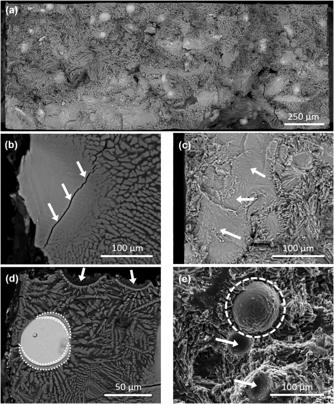
a SEM image of the fracture surface. b BSE image of the top view of an intermetallic patch near fracture surface with arrows highlighting crack propagation through the patch. c SEM image of the cross-section view of an intermetallic patch at fracture surface with arrows highlighting facet features. d BSE image of a retained titanium particle near fracture surface with delamination from matrix material in shaded highlights and fractured particle seats highlighted with arrows. e SEM image of a delaminated titanium particle at the fracture surface highlighted in dashed circle and fractured particle seats highlighted with arrows.
In addition to causing matrix material deficiency, high content of Ti addition also creates patches of intermetallic instead of whiskers at localized Ti-rich regions. These patches of intermetallic provide no deflection to cracks, as shown in the nearly straight crack path highlighted in Fig. 2b. The lack of crack deflection contributes to the sudden onset of fracture, which was observed in the testing of all three specimens. While the stress-strain curve shows some degree of plasticity, the material fracture behaviors were closer to that of brittle materials. The cross-section of the fracture surface also supports the presence of brittle fracture within the specimens, as shown in the bottom left section of Fig. 2a, which has a much smoother fracture surface compared to other regions. Upon closer inspection as shown in Fig. 2c, the faceted fracture features confirm the presence of cleavage fracture, which is unique to brittle fracture events. Therefore, the elimination of these intermetallic patches is expected to reduce the onset of brittle fractures in localized regions of the composite material, improving the overall material ductility.
Finally, retained Ti particles delaminating from the peripheral matrix material induce spherical stress concentrations within the composite material under tension. When the adhesion between the matrix material and the particle inclusion is poor, the inclusion acts as a spherical void, creating stress concentration points and promoting internal crack initiation21,22. Figure 2d offers a glimpse into the particle delamination phenomenon that likely contributed to the early crack initiation and significant loss of ductility. Delamination is present in the form of crescent-shaped voids (highlighted in shades) on either side of the particle, normal to the loading direction. Two partial particle recesses where particles delaminated are also highlighted with arrows in Fig. 2d, with the fracture line going right across both particle recesses. This is likely the result of developed crescent-shaped voids around the particle joining around the middle of the particle and creating further crack propagation in the matrix material around the particle. The cross-section view as shown in Fig. 2e also confirms the presence of particle delamination, with the major crack developing around the middle plane of the particle that’s normal to the loading direction. The remaining partial particle recesses after fracture (highlighted with arrows) show unique spherical surface features with uneven patterns, matching that of the remaining particles.
Characteristics of AMC with whisker reinforcement
To combat the three sources of reduced ductility mentioned above, two factors of the feedstock powder mix were altered:
-
1.
The content of Ti addition in the feedstock powder mixture.
-
2.
The size distribution of Ti addition particles.
The Ti addition content in the feedstock (10–30 wt%) has been shown in our previous study to directly correlate with the volume fraction of intermetallic whiskers in the printed composite material, as well as the amount of retained unmelted Ti particles16. It was expected that reducing the content of Ti addition could resolve the problem of insufficient matrix materials between reinforcement whiskers and the formation of intermetallic patches at localized Ti-rich regions. This would in turn improve the ductility of the composite material. However, since both the intermetallic content and the retention of unmelted particles similarly depend on the feedstock Ti content, reducing the Ti content alone to eliminate unmelted Ti particles could limit the range of reinforcement intermetallic content. Additionally, the stochastic nature of powder-based DED process may still result in the retention of larger-diameter Ti particles. Therefore, to promote the full reaction of Ti addition particles and avoid retention of unmelted particles in the composite material, reducing the Ti particle size appears to be a viable approach, as discussed in “Discussion”. 15–45 µm particle size Ti-6Al-4V (Ti64) feedstock for powder bed fusion (PBF) use was chosen due to material availability and storage limitations in the lab. While the chemistry alteration of Ti addition material introduced vanadium element into the material system, the effect of the additional element is determined to be negligible, as discussed in more detail in “Discussion”.
The microstructure of tensile specimens extracted from sample blocks printed using PBF-sized (15–45 µm) Ti64 feedstock addition is shown in Fig. 3a, b. The two different feedstock mixtures used that contains 4 wt% and 8 wt% Ti (from PBF-sized Ti64 powder addition) are denoted FP04 and FP08, with detailed composition shown in Table 1. The gauge section shows minimal lack-of-fusion porosity and little to no retained Ti addition particles. Some gas pores are present in the specimens and the degree of porosity shows variations across different specimens with no correlations to the feedstock content or intermetallic volume fraction. Thus, these gas pores are most likely process-induced instead of material-induced and can be eliminated with more rigorous effort in process optimization. A closer look at the microstructure as shown in Fig. 3b confirms the elimination of intermetallic patches and a considerable reduction in the amount of unmelted Ti addition particles. The uniform distribution of reinforcement intermetallic whiskers with no preferential orientation matches that in prior specimens. The morphology as well as the size of the whiskers also stays consistent with prior specimens. This batch of samples is denoted as samples with whisker reinforcement.

a SEM image of the tensile specimen gauge section top surface overview, and b Close-up SEM image showing material microstructure. c Stress/strain curves of the tensile specimens with indicated intermetallic volume fraction and cast pure Al from literature29.
Tabulated results of the mechanical testing are shown in Table 2 with all specimens denoted using feedstock Ti content (4, 8, or 20), sample block index (a, b, or c), and specimen index (1, or 2 if more than one specimen extracted per sample block). For example, specimen “4a2” is referring to the second specimen from sample block a printed using feedstock containing 4 wt% Ti. Compiled stress-strain curves of all tested specimens are shown in Fig. 3(c) with measured intermetallic volume fraction labeled for each curve. The stress-strain curves are also color-coded to provide a more straightforward representation of the correlation between mechanical performance and volume fraction of reinforcement intermetallic. It can be observed that the varying degree of process-induced gas porosity defect shows the impact on ductility levels of different specimens with similar volume fractions of intermetallic. In addition, specimens from the same sample block showed a similar volume fraction of intermetallic under microscopy inspection, but specimens from different sample blocks of the same feedstock showed some degree of variation in the amount of intermetallic reinforcement whiskers. While the root cause of this variation requires further investigation, the high flowability of the feedstock powder and continuous vibrations at the feedstock hopper during DED processing are likely contributing factors. The vertical feedstock hopper on the specific L-DED system used in this study stores the powder before it enters a horizontal feeding/metering mechanism. It is likely that the highly flowable pre-mixed powder experienced sedimentation due to the drastic density difference between Al and Ti, combined with the vibrations of the hopper. Consequently, a localized increase in Ti content could occur at the bottom of the premixed feedstock. This phenomenon could affect the correlation between the feedstock mixing ratio and the intermetallic content, as seen most notably in samples printed with the FA08 feedstock in Table 2. However, using multiple hoppers to achieve on-the-fly powder mixing, instead of using pre-mixed feedstock powder, could improve the feedstock-product correlation in future studies.
Despite losses in ductility observed in specimens with process-induced defects, the specimens printed with PBF-sized Ti addition show great improvement in ductility. As shown in Table 2, the ductility levels of all eight tested specimens with whisker reinforcement, including the ones with defects, range from 2.5% to 8.3%, much higher than that of specimens with hybrid reinforcement. The UTS levels of all tested specimens also show improvement from prior specimens with hybrid reinforcement as well as pure aluminum as the matrix material, reaching 163.4 MPa for the defect-free sample with the highest volume fraction of intermetallic. In addition to improvement in both ductility and UTS from AMC with hybrid reinforcement, the AMC with whisker reinforcement also show improved yield strength and UTS across the board when compared to the pure aluminum used as matrix material, as shown in Table 2. The different mechanical responses from all specimens with whisker reinforcement also demonstrate the tunability of the AMC, which is discussed in detail in “Discussion”.
Fractography results, as shown in Figure S2, also indicate a successful transition to a ductile fracture surface upon altering the particle size distribution and content of Ti addition particles used. The consistency of fracture surface features was observed across the entire fracture surface of all tested specimens with whisker reinforcement and Fig. S2a shows one example of the fracture surface with no cleavage fracture features present. Close-up looks at different regions of the fracture surface as shown in Fig. S2b, c confirm the presence of numerous dimple features, which indicate the fracture as a ductile fracture, consequent to plastic deformation-induced microcracks and their coalescence. Further investigations into the strengthening mechanism of the composite material with only whisker reinforcement are discussed in “Discussion”.
Discussion
As stated in “Characteristics of AMC with whisker reinforcement”. Characteristics of AMC with whisker reinforcement, PBF-sized (15–45 µm) Ti64 powder is used as the source of Ti addition in the feedstock powder mix. While the Ti particles are altered to the PBF size range, the base aluminum powder is still in the DED size range, dominating the overall feedstock powder characteristic. This maintains the flowability of the powder during the powder-delivering stage and the powder catchment efficiency is maintained since larger particles are more likely to break the surface tension of the melt pool upon impact23. Meanwhile, the reduced particle size significantly increases the surface area to volume ratio of the Ti particle as shown in Fig. 4. The implication of increased surface area to volume ratio is reduced mass per unit surface area, resulting in the Ti particles potentially reaching higher temperatures before entering the melt pool. This is confirmed by numerical simulation which shows Ti64 powder particles of 25 µm diameter reaching a maximum temperature of around 1350 K just before dissolving in the melt pool while particles of 45 µm diameter can only reach less than 900 K in the same condition24. Particles with a diameter in the range of 15–45 µm are also shown to converge better in a powder jet than that of 45–105 µm when delivered with a coaxial nozzle, meaning mixing PBF-sized Ti addition particles could result in a larger amount of Ti material entering the melt pool in IRP25.

Comparison of surface area to volume ratio of feedstock particles in different size distribution.
The tunability of mechanical properties of TiAl3 whisker-reinforced AMC is shown in Fig. 3c with the compiled stress-strain curves of all tested specimens with different volume fractions of intermetallic. The correlations of strength and ductility of specimens against their reinforcement content are plotted in Fig. 5. As shown in Fig. 5a, the offset yield strength (as listed in Table 2) of specimens correlates well with the intermetallic volume fraction, exhibiting a near-linear increasing trend with minimal impact from process-induced defects. This correlation shows good agreement with the rules of mixture. The ultimate tensile strength of defect-free specimens also shows a good monotonic correlation with intermetallic volume fraction as shown in Fig. 5b. However, process-induced defects in some of the specimens cause moderate scattering in the overall dataset, likely due to defect-induced premature fractures. The ductility of specimens displays significant scattering, as shown by the poor overall fit in Fig. 5c. Despite this, defect-free specimens show a clear monotonic decrease in ductility with increasing intermetallic reinforcement content. However, in samples with defects, no clear trend is observed due to the pronounced effect of gas porosity defects on ductility.

Plots of correlations between the intermetallic volume fraction and a offset yield, b ultimate tensile strength (UTS), c strain at fracture of tensile specimens.
Load transfer is one of the most crucial strengthening mechanisms in composite materials such as AMCs, where the soft matrix material is reinforced by the inclusion of a hard rigid reinforcement phase. To study this strengthening mechanism of the TiAl3 whisker-reinforced AMC, the top surface of the fractured specimens was imaged at high magnification and correlated to the same region before mechanical testing. As shown in Fig. 6a, the gauge section of the sample near fracture shows good homogeneity of whisker reinforcement dispersed in the matrix material. The major crack path (marked by the left dashed line) of the fracture in Fig. 6b shows no preferential development towards the traces of unmelted Ti addition material or the porosity defect when referenced to the prior-testing state shown in Fig. 6a. Figure 6c, d offer a closer look at the matrix-whisker interaction close to the fracture surface. No whisker pull-out events can be observed across the dimpled fracture cross-section shown in Fig. S2, demonstrating the strong interface cohesion between the matrix material and the whisker phase. Therefore, most of the microcracks observed are present at the interior of the TiAl3 whisker reinforcement, as shown in Fig. 6c, d, while the strong interfacial adhesion between the aluminum matrix and TiAl3 whiskers likely prevented crack initiations at the interfaces. These microcracks are evident in TiAl3 whiskers that are aligning or close to aligning with the loading direction as shown in Fig. 6c, d. Numerous slip traces of the matrix material are present around the microcracks, which are highlighted in Fig. 6c. The contained microcracks and slip traces in the peripheral matrix material demonstrate effective load transfer between the reinforcement phase and the matrix material. Large amounts of microcracks are arrested by ductile matrix material after serving as one of the major energy dissipation pathways during the damage evolution. The random orientation of whisker reinforcements also provides some degree of crack deflection, which consequently increases the difficulty of crack development. This is reflected in both the jagged nature of the major crack path and the zigzag crack openings that initiate from the stretched pore, as highlighted by dashed lines in Fig. 6b. Ultimately, the fracture of the whisker-reinforced AMC is through the coalescence of adjacent microcracks into larger cracks as highlighted in Fig. 6d. The necking phenomenon that is characteristic of ductile materials, is also reflected in the gauge section width reduction near fracture, as shown in Fig. 6b.

a Overview of gauge section prior to tensile loading. b Post-fracture overview with jagged crack path highlighted by dashed lines. c, d Close-up details of microcracks in intermetallic whiskers, slip lines in matrix material (highlighted in dashed lines), microcracks inside intermetallic whiskers (highlighted in yellow shade), and coalesced microcracks (highlighted in dashed lines).
In order to understand the different contributions towards the overall strengthening of TiAl3 whisker-reinforced AMC, the strengthening contribution of load transfer is first estimated using the shear lag model for reinforcement with large aspect ratio ((S, >, 2)):
and modified shear lag model for reinforcement with small aspect ratio ((Sle 2)):
where ({sigma }_{{cy}}) is the yield strength of the composite, ({sigma }_{{my}}) is the yield strength of the matrix material, (S) is the average aspect ratio of the reinforcement, and ({V}_{p}) and ({V}_{m}) are the volume fractions of the reinforcement and matrix, respectively 26. The aspect ratio (S) of the TiAl3 whiskers in the current study are characterized from 2D back-scattered electron microscopy (BSE) image of the microstructure using ImageJ Analyze Particles function, where aspect ratio is the ratio between the major and minor axes of the ellipse fitted to the detected whiskers. A large variation in (S) of over 10,000 measured whiskers is observed, with values of (S) ranging from 1.01 to 18.03, having an average value of 3.04 ± 1.80. The wide spread of the whisker aspect ratio makes it inadequate to use either model alone. The theoretical strengthening value of each measured whisker (for a particular reinforcement volume fraction) is calculated using the appropriate shear lag model for its aspect ratio, and the overall strengthening effect is taken as the average of all strengthening values from individual whiskers. The strength improvement from load transfer strengthening are calculated for the specimens with the lowest and highest content of reinforcement whisker, as listed in Table 3.
Materials synthesized using AM often show refined grain structures compared to their cast counterparts. The high cooling rate is considered to be one of the driving forces of this grain refinement. While the load transfer strengthening is shown in the previous section to play a major role in the strengthening of TiAl3 whisker-reinforced AMC, the contribution from grain refinement unique to AM shall not be overlooked. Electron backscatter diffraction data shown in Fig. 7 confirms the presence of grain refinement in AMCs synthesized with DED-based IRP in the current study. The average grain size of the matrix aluminum grains in specimens printed with LPBF size Ti64 powder is shown to be 10.79 µm and 8.63 µm in Fig. 7a for low and high content of intermetallic reinforcement. This indicates a limited effect of increasing reinforcement content on further grain refinement level.

a Aluminum grain size distributions in regions from samples with low and high intermetallic volume fraction (IVF). b, c Inverse pole figure of aluminum grains in regions containing low- and high-volume fraction of intermetallic (colored gray).
In addition to load transfer strengthening, contribution of grain refinement towards the overall strengthening of TiAl3 whisker-reinforced AMC is estimated using the Hall-Petch relationship:
where ({sigma }_{0}) is materials constant for the starting stress for dislocation movement, (k) is the strengthening coefficient, and (d) is the average grain diameter27. The value of 0.07 MPa·m0.5 is taken as the (k) for pure aluminum28 and ({sigma }_{0}) is back calculated using the actual yield strength of cast pure aluminum29 and grain size30,31, as listed in Table 3. The calculated theoretical yield strength of AMC with low and high volume fraction of intermetallic is compared to that of the cast pure aluminum to estimate the Hall-Petch strengthening contribution, as listed in Table 3. It is important to note that, due to the unavailability of yield strength and grain size data of L-DED pure aluminum, the empirical Hall-Petch relationship used here is only meant to provide approximate contribution of grain refinement strengthening. Since these calculations are based on approximations, the theoretical values do not exactly match the experimental results. However, the approximations still provide a useful estimate of load transfer strengthening from TiAl3 whiskers and grain refinement strengthening from Al matrix grains.
With a higher amount of intermetallic reinforcement in the AMC, the grain refinement level of matrix Al marginally increases, causing a slightly higher amount of estimated Hall-Petch strengthening. The levels of load transfer strengthening, however, shows a larger difference between specimens with different levels of reinforcement content. The strength enhancement of whisker-reinforced AMC in the current study is a compounded result of the Hall-Petch strengthening from grain refinement and the load transfer strengthening. The tunability of the mechanical properties of the AMC comes from different levels of Hall-Petch and load transfer strengthening, with load transfer strengthening playing a more dominant role.
While the grains with reduced size can provide grain refinement strengthening, it is also worth mentioning that reducing the grain size and grain aspect ratio can help reduce solidification cracking, which is seen as a common hindrance to the wide adoption of aluminum in AM. Owing to the lower cooling rate of 103 K/s in powder L-DED32,33,34 when compared to the 105 – 106 K/s cooling rate of powder L-PBF35,36, the grain refinement from increased cooling rate is not as pronounced in DED aluminum materials. While printing un-reinforced pure aluminum with AM is intrinsically challenging, the successes in DED of aluminum alloys tailored for AM, such as Al-Mg alloys, show an average grain size of around 80–90 µm with the presence of columnar grains37,38. This approximates to an order of magnitude reduction in grain size from DED cooling rate when compared to the grain size of cast pure aluminum at around 1000 µm30,31. Some efforts, including adding Sc-Zr alloying elements and TiC/TiB2 nanoparticle grain refiners, have shown success in reducing the grain size of DED aluminum materials to around 4–16 µm with a reduction in grain aspect ratio as well39,40,41. Interestingly, the average Al grain size of around 10 µm in whisker-reinforced AMC material synthesized in the current study also shows further grain refinement than that from the DED cooling rate alone. It is worth noting that a minimal amount of vanadium ( < 0.4 wt%) is introduced in the Ti-Al binary system of the current study when Ti64 powder is used as the source of Ti addition. Vanadium (V) addition is shown to be a source of grain refinement in the casting of commercially pure aluminum by promoting heterogeneous nucleation with the formation of Al10V particles ranging 20–160 µm in size30. However, no Al-V intermetallic phase is observed in scanning electron microscope (SEM) images or detected in X-ray diffraction (XRD) analysis in the current study. Additionally, the computed Al-Ti-V ternary liquidus projection also indicates that TiAl3 is the only preferential intermetallic forming for compositions with predominantly Al ( > 80 wt%) and minimal vanadium content ( < 1 wt%)42. With no grain refining nanoparticles added or a significant amount of Al-V intermetallic formed, the additional grain refinement indicates the potential presence of a different grain refinement mechanism that relates to the formation of TiAl3 intermetallic.
Operando X-ray diffraction experiments are carried out to provide some insights into the solidification path of the TiAl3-reinforced AMC material and the potential grain refinement mechanism. Due to the X-ray detector acquisition rate and the laser spot size of the simulated AM setup, the laser scanning speed is set to 40 mm/sec to capture the diffraction pattern at an adequate temporal resolution. This laser scanning speed is slightly higher than that of tensile sample fabrication on the DED system at 25 mm/sec (1500 mm/min). The resulting higher cooling rate in the simulated PBF setup allows less time for the mixing of Al and Ti and their subsequent reactions, making it a more challenging condition for TiAl3 formation compared to DED and increase the likelihood of local reinforcement content heterogeneity due to insufficient dispersion of reaction product before full solidification. The laser power used for the operando study is 70 W, much lower than the 330 W used in the DED system. However, it is worth noting that the laser interaction volume, which is calculated using laser spot size and layer thickness, is also different for the two processing methods used. The ratio between the linear energy densities of DED and PBF processing parameters used in the current study is 9.1, which is very similar to the ratio of 10.1 between the different laser interaction volumes of the two processing methods. The similarity in energy density per unit interaction volume indicates the close resemblance of the operando study to the actual DED sample fabrication for microstructural and mechanical testing.
Shown in Fig. 8a is a heatmap compiling 1D XRD curves of one complete process of AM material synthesis, with each row representing one time instant and the process develops from bottom to top on the time axis. Specific locations on the X-axis (scattering vector Q) correspond to unique peaks of formed phases, which are labeled on the top of the heatmap. The material system starts with only Al and Ti as feedstock material, which fully melts in the X-ray detection volume, losing crystallinity and signals at all relevant peak locations, around 0.16 s when the laser passes through the X-ray window. The material in the X-ray detection volume stays molten briefly before nucleation events take place, signified by the reappearance of peak signals. The temperature inside the meltpool is higher than the starting powder when solidification starts, causing thermal shifts to all peaks, which eventually stabilize as the material fully solidifies and cools down. Taking a closer look at the start of solidification, as shown in the close-up heatmaps in Fig. 8b–d, signals matching the unique TiAl3 peaks appear first, followed by the appearance of peaks signifying nucleation of Al. The sequence of TiAl3 formation long before the formation of Al grains is consistent across the entire heatmap for different unique peaks of TiAl3 and Al. While the same solidification pathway is observed in operando experiments using both feedstock FA04 and FA08, the results from the experiment using feedstock FA08 are presented here due to the higher amount of intermetallic phase formed, which generated stronger signal intensities.

a Temporal heatmap of compiled azimuthal-integrated X-ray diffraction data through the entire thermal cycle in simulated AM process and, b–d Close-up details of the solidification period showing the appearance sequence of difference phases.
The findings from the operando study shed light on the potential grain refinement mechanism in IRP of AMC, in addition to the high cooling rate in AM. As illustrated in Fig. 9a–c, the vertices as well as ends of some reinforcement phases formed prior to aluminum solidification could encourage heterogeneous nucleation events. This correlates to the observed instances of one intermetallic whisker spanning across multiple adjacent grains, as shown in Fig. 7b. In contrast, as illustrated in Fig. 9d–f, during the solidification of AM-processed unreinforced aluminum material, the lack of heterogenous nucleation seeds and the steep thermal gradient could favor the growth of existing grains from the prior layer43,44,45. This could consequently promote the formation of thermally driven, highly directional columnar grains, which restricts the motion of back-feeding liquid during solidification, thereby increasing the susceptibility to solidification cracking46,47,48. Titanium, as the only addition to the pure aluminum matrix material, nearly fully transforms into the TiAl3 whisker reinforcement phase during IRP, as shown in “Characteristics of AMC with whisker reinforcement”. Inclusions like TiAl3 whiskers, if formed prior to the matrix material solidification, could serve as heterogeneous nucleation sites during the formation of matrix material grains. In fact, the TiAl3 phase, with its structure being a tetragonal variant of the cubic lattice and a lattice parameter of 3.96 Å, appears to function effectively as an inoculant for aluminum, which has a closely matched cubic lattice parameter of 4.04 Å. This mechanism of promoting heterogenous nucleation with inoculants having similar crystalline form is rooted in the concept of isomorphic inoculation, which is shown to create effective grain refinement in TiAl alloy castings20. While the hypothesized grain refinement mechanism could explain the additional level of grain refinement observed in the TiAl3-reinforced AMC, its effect is limited to a certain extent. This is reflected in the minimal further reduction in average grain size with the increase in the intermetallic volume fraction, as shown in Fig. 7a. Nonetheless, the finding applauds the hypothesized new avenue of grain refinement in IRP, where the prior-formed TiAl3 whiskers disperse within the melt pool due to the Marangoni effect in AM and provide heterogeneous nucleation sites for the formation of Al grains. The number of matrix Al grains grows with the increased nucleation events which could lead to a crowding effect that restricts excessive growth of the Al grains.

a Intermetallic phase solidifies prior to matrix material nucleation, b Heterogeneous nucleation sites on the intermetallic phase, c Refined grains in matrix material, d Impurities and grains from the prior layer in unreinforced matrix material, e Nucleation from impurities and directional grain growth, f Large directional grains with potential solidification cracks.
The current study demonstrates the tunable mechanical performance of TiAl3 whisker-reinforced AMC fabricated with IRP. The microstructure of the AMC is optimized by the elimination of unmelted Ti particles. Fabricated AMC with different contents of intermetallic reinforcement shows tunable mechanical properties between high ductility retention and enhanced strength. Different roles of TiAl3 whisker from the in-situ reaction are revealed in terms of mechanical properties and microstructural evolution. The main findings of this work are summarized as follows:
-
(1)
Using PBF-sized (15–45 µm) Ti particles in DED-based IRP shows no compromise in material processability and resolves ductility limitations from poor interfacial adhesion between matrix Al and unmelted Ti particles. The optimized microstructure consists of mainly uniformly dispersed TiAl3 whiskers of refined size.
-
(2)
TiAl3 whisker reinforced AMC demonstrates excellent tunability between high strength enhancement and high ductility retention with different content of reinforcement phase.
-
(3)
Higher content of reinforcement does not cause significantly further grain refinement, thus Hall-Petch strengthening is similar in AMC reinforced with different content of reinforcement phase. However, the contribution of load transfer strengthening increases with a higher content of the reinforcement phase.
-
(4)
TiAl3 whiskers not only reinforce the matrix material from load transfer strengthening but also aid in grain refinement by providing heterogeneous nucleation sites through in-situ inoculation. The degree of grain refinement is higher than that from the high cooling rate of DED alone. The refined grains in TiAl3-reinforced AMC also alleviate AM Al processing difficulties, such as the solidification cracking from the formation of large columnar grains.
Methods
Material synthesis and sample extraction
In this study, the AMC material was synthesized with the IRP technique16, using pre-mixed feedstock powder on a Formalloy X2 DED system. The laser spot size of this system is 1.2 mm at working distance and all samples were printed with the laser beam in focus. The base metal powder was commercially pure (CP) aluminum from Valimet with particle size 45 to 106 µm. Two different sources of titanium addition were used in the current study as feedstock additions to the base metal powder, which includes CP Ti with particle size 45–106 µm and Ti64 with particle size 15–45 µm from AP&C. Different mixing ratios used in feedstock preparation are listed in Table 1. While the effects of Ti addition powder particle size distribution and mixing ratios are discussed in detail in “Characteristics of AMC with whisker reinforcement” and “Discussion”, the compositional change is mainly due to powder availability and storage limitations in the lab. Although using Ti64 alloy in place of CP Ti introduces vanadium as a ternary element in the otherwise binary Al-Ti system, vanadium’s minimal content and its lack of impact on aluminum microstructure, as discussed in “Discussion”, mean that the compositional change does not introduce additional variables of concern for this. All powder of different source material were weighed using precision scales prior to mixing. All feedstock powder was combined from powder of source materials in a plastic bottle and mechanically mixed in low energy ball mill without media for 30 min before use.
Sample blocks sized 30 mm × 16 mm ×2 mm (length × width × height) we1re fabricated in an argon-inert atmosphere to extract specimens for mechanical and microstructural characterizations. The substrate material for all sample blocks was grade 2 titanium. The process parameters used for samples printed with CP Ti feedstock addition and Ti64 feedstock addition are detailed in Table 4. The differences in processing parameters are likely due to the different particle size range of the feedstock Ti addition powder used.
Micro-tensile test coupons were extracted from the sample block using electric discharge machining (EDM) by cutting the contour of the specimen profile before slicing the specimen off of the substrate material. The gauge section of the specimen was 2 mm in width and 8 mm in length. The detailed drawing of the miniature tensile bar used is shown in Figure S1. Each specimen was consequently ground on both sides to 400 grit level to remove the oxide layer formed during EDM. To reveal the internal microstructures, one side of each sample was further ground with 600, 800, 1200 and 2000 grit grinding paper, followed by polishing with 1 µm, 0.3 µm, 0.1 µm alumina solution and finally 0.08 µm colloidal silica solution. The unpolished sides of each sample were spray painted white and finely dotted with ink for strain measurement during micro-tensile tests. In addition, the remaining printed material after extraction of tensile specimens were polished using the aforementioned sequence of steps to 0.08 µm colloidal silica solution for grain size characterizations detailed in “Microstructural Characterization”.
Microstructural characterization
Scanning electron microscopy (SEM) and Back-scattered Electron microscopy (BSE) were performed on the polished top surface of all tensile specimens before tensile testing and after tensile testing to reveal the microstructures. SEM and BSE images were also taken at the fractured surface cross-section of the specimens to reveal the surface morphology. All SEM and BSE microscopy was performed using a Tescan Mira Field Emission SEM. Electron backscatter diffraction (EBSD) analysis was performed on the polished cross-section of the remaining material after tensile coupon extraction to obtain grain size statistics in the as-printed state. EBSD data were acquired using a Zeiss Sigma 500 SEM with a step size of 0.15 µm, an accelerating voltage of 20 keV, and a view field of 150 µm by 112.5 µm. Grain size statistics were extracted from EBSD data using the ATEX software49 with misorientation angles larger than 15° set as the grain detection threshold. The grain size of the largest 100 grains was plotted to represent the grain size distribution. Aspect ratio statistics of intermetallic whiskers are collected using ImageJ’s built-in “analyze particle” function on more than 60 BSE images of several specimens after automatic thresholding.
While each specimen shows high levels of homogeneity, samples extracted from different sample blocks that were printed using feedstock powder with the same titanium content displayed variation in intermetallic volume fraction. The potential sources of intermetallic volume content differences in sample blocks printed using the same feedstock are discussed in more detail in “Characteristics of AMC with whisker reinforcement”. To obtain actual intermetallic volume fraction of each tensile specimen, surface X-ray diffraction (XRD) analysis was performed on the polished top surface of the gauge section of the tensile specimens, with two acquisitions per specimen covering the entirety of the gauge section. The two-theta range was 35–85 degrees to capture all relevant phases with a 0.02-degree step size. The intermetallic volume fraction of each XRD acquisition is converted from mass quantification of different phases obtained using Rietveld analysis in the MDI Jade software and the intermetallic volume fraction of each specimen is the average value of the two XRD acquisitions.
Mechanical characterization
The micro-tensile tests of all specimens were performed on a Deban Microtest system with a 2 kN load limit. The extension rate was 2 × 10⁻⁴ s−1 for all tests and all specimens were preloaded to 20 N for proper sample seating before data acquisition. Specimens’ thickness ranges from 500 µm to 700 µm and measured actual thickness before tensile testing was used for calculating stress values from the force output of the test system. The gauge sections of specimens were imaged continuously during the tensile tests using a Mako U503B CMOS camera with a Kowa LM50JCM lens (50 mm focal length, F/2.8 aperture). The imaging setup was mounted above the tensile testing setup with sufficient lighting and adequate distance such that the entire gauge section was captured in the field-of-view. Images of size 2592 pixels × 1944 pixels (approx. 4 μm/pixel) were taken at a 2 Hz acquisition rate during the entire testing process until fracture onset. The strain values were extracted from the acquired image series in post-processing digital image correlation (DIC) using the Zeiss GOM_correlate 2019 software. A surface component was created on the gauge section of the specimen from each image series with the facet size and point distance parameters set as default values of 19 pixels and 16 pixels respectively. The strain values were extracted from 3 virtual strain gauges in the form of 2-point distance elements on the created surface component. The average strain values of the 3 virtual strain gauges were used as the strain time series of the tensile tests. In total, 11 specimens were tested in micro-tensile tests, which include 3 specimens from samples printed using feedstock FP20, 4 specimens from samples printed using feedstock FA04, and 4 specimens from samples printed using feedstock FA08.
Solidification sequence identification via operando synchrotron study
Operando transmission X-ray diffraction experiments were conducted at beamline 1-ID, Advanced Photon Source (APS), Argonne National Laboratory to uncover the solidification sequence of phases in the aluminum matrix composite material. The experimental setup at APS 1-ID is specifically designed to perform diffraction analysis50,51, and it was retrofitted to simulate the additive manufacturing process, with details of the setup illustrated in Fig. 10. A 61.332 keV X-ray beam (wavelength = 0.202152 Å) was focused vertically to 35 µm (full width at half maximum) and slit down horizontally to 50 µm for the experiment. The center of the X-ray beam was positioned vertically in the middle of the 250 µm thick powder layer and a high-speed photon counting detector (Pilatus3X 2 M CdTe) was positioned downstream with a distance of 660 mm to the sample for capturing diffraction patterns of the material during the entire laser melting process. The laser spot size used in all experiments was 95 µm. The powder bed was 300 µm wide in the X-ray direction and it was kept under an argon-inert atmosphere during the laser melting process. The powder mixtures FA04 and FA08 were used as feedstock. The processing parameters were chosen as 70 W for laser power and 40 mm/s for laser scanning speed due to the acquisition rate limitations of the detector. The operando diffraction data were acquired at an exposure time of 1 ms and a rate of 250 Hz for 1000 frames per laser scan. Each frame of the acquired data was integrated along the azimuthal direction and consequently binned in the two-theta direction with a 0.01-degree bin size using the GSAS-II software. The resulting temporal heatmap and the matching of phases are discussed in “Discussion”.

a Overall system architecture including laser source, inert atmosphere chamber, X-ray path, and detector placement, with annotated azimuthal (η) and two-theta (2θ) directions, b Detailed view of the powder bed construction and the laser interaction volume within.


Responses