Electrochemical reactor with carbon membrane electrodes for efficient phenol removal via anode and cathode synergism

Introduction
Electrochemical membrane reactors (EMRs) based on the advanced oxidation processes (AOPs) have been progressively regarded as one of the most promising candidates for the next-generation water purification technologies1,2,3. Specifically, with the ability to decompose and remove pollutants in situ, EMR holds the promise of outperforming traditional membrane filtration technologies that rely solely on the physical retention and transfer of pollutants4. Moreover, AOPs endow EMRs with multiple functions, such as electrocatalytic degradation5, electro-Fenton degradation6, electro-disinfection7, antifouling8, and so on. Noteworthy, the membrane filtration process further improves the efficiency of electrochemical processes through enhanced mass transfer9 and confinement effects10. As a result, this integration of electrochemical and membrane filtration achieves the superior treatment efficiency required in wastewater treatment processes11.
An EMR typically consists of an anode and a cathode. Among, EMR (EMR-A) with an anode membrane as the working electrode has been widely used for industrial wastewater treatment12,13,14. For instance, a fixed-bed EMR was developed using a porous Ti membrane loaded with MnOx nanoparticles as the anode and a stainless-steel mesh as the cathode for synthetic phenol wastewater treatment in our previous study5. According to the results, the eight-stage fixed-bed EMR-A was able to remove 96.0% of phenol (188 mg L–1) and 89.3% of COD with an energy consumption (EC) lower than 0.74 kWh kgCOD–1. Similarly, EMR (EMR-C) utilizing a cathode membrane as a working electrode has also been developed for wastewater treatment15,16,17. Specifically, EMR-C with graphene-modified electro-Fenton catalytic membrane as a cathode and Pt mesh as an anode was fabricated for in-situ degradation of the low-concentration antibiotic florfenicol. Its removal efficiency was as high as 90%, which was much higher than the 50% efficiency of electrochemical processes or the 27% efficiency of single filtration processes18. Currently, most relevant studies focus on half-cell reaction using membrane electrodes as anode or cathode. In this case, the counter electrodes played a minor role, leading to low efficiency and energy wastage. At present, EMR technologies still face great challenges in terms of efficiency and EC in practical industrial applications.
To overcome this critical issue, an alternative approach is to use EMRs coupled with both a working cathode and anode for pollutant degradation. Here, a pair of conductive membranes as dual electrodes can be used to constitute a complete EMR (EMR-P), which will increase the removal efficiency and reduce the EC. Recently, there have been several reports focusing on the feeding sequence of the anode and cathode of the EMR-P. For example, an EMR-P was assembled using a tubular concentric electrode configuration with a titanium suboxide ceramic anode and a stainless-steel cathode for chlorophenol removal. In CA mode (feed flowing through the cathode and then to the anode), the removal rate after 5 min of electrolysis was 99%, which was much higher than that obtained in AC mode of 16.8% (feed flowing through the anode and then to the cathode)2. In contrast, Peng et al. reported an EMR-P using a pair of carbon fiber felt-based electrodes for the degradation of methylisothiazolinone. The degradation performance in AC mode (~90%) was higher than in reverse CA mode (~50%)19. Remarkably, the obtained results were contradictory as a result of the complexity of the electrochemical reactions in an EMR-P with a pair of working electrodes. Additionally, the electrode distance between the anode and cathode also affects the electrochemical reactions between the dual electrodes. For instance, a pair of TiO2-x@CN membrane electrodes was used in an EMR-P for propranolol treatment (20 mg L–1). At a relatively short electrode distance of 0.9 mm, the cathodic reactions adversely affected the anodic reactions. Similarly, the anodic reactions could inhibit the generation of ({1atop}{rm{O}}_{2}) at a short distance of 0.9 mm, whereas the production of ({1atop}{rm{O}}_{2}) was promoted at long distances of 9 mm. Furthermore, the propranolol removal rate in CA mode was approximately 68% under the electrode distance of 0.9 mm and 99% under the distance of 9 mm4. Regardless of whether the EMR-Ps operate in CA or AC mode, the pollutant degradation process inevitably interferes with each other when the pollutant flows through the two membrane electrodes successively. Specifically, the degradation mechanism of pollutants in EMR-Ps needs to be clarified.
Membrane electrodes with low electrochemical activity also limit the development of EMR technologies. To address this challenge, an approach to load TiO2 nanoparticles onto carbon membrane (CM) was reported in our previous work20. It served both as a filter and an anode of the EMR-A for landfill leachate treatment. As a result, the removal rates of COD, NH4+-N, and TN were up to 82.0%, 86.5% and 76.3%, respectively. The EC of EMR-A was only 4.81 kWh kgCOD–1. The achieved EMR with high efficiency and low EC was associated with the synergetic effect of electrochemical oxidation and enhanced mass transfer. Furthermore, a self-supported CM electrode with a high porosity of 42.3% and a high surface area of 450.7 m2 g–1 was developed by carbonizing activated carbon (AC) and phenolic resin under H2 atmosphere in our previous work21. Specifically, as the cathode of the EMR-C, the CM contained numerous defects and carbon edges, which promoted the oxygen reduction reaction activity, resulting in a highly efficient H2O2 synthesis rate of 5.21 mg h–1 cm–2 and a current efficiency of 88% for H2O2 electrosynthesis. This sets an excellent precedent for the cathodic electro-Fenton reaction based on the electrosynthesis of H2O2. Therefore, employing high-performance electrochemical membrane electrodes can further enhance the functionalities of EMR-P systems to enhance treatment efficiency.
The aim of this study is to construct a flow-through EMR-P system (Fig. 1a) for highly efficient phenol removal using a self-supported activated carbon-based CM as cathode and a TiO2-loaded CM (TiO2/CM) as anode (Fig. 1b). Specifically, the EMR-P without ion-exchange membrane and consisting of two permeates from anodic electrocatalytic and cathodic electro-Fenton processes. In contrast, EMR-C with only cathode permeate was built using CM as the cathode and Ti plate as the anode (Fig. 1c). Similarly, EMR-A with only anode permeate was also constructed using TiO2/CM as the anode and Ti plate as the cathode (Fig. 1d). Notably, the degradation dynamics and reactive species of EMR-P, EMR-C, and EMR-A were systematically investigated. Finally, the synergistic mechanism of EMR-P was further explored.

a The flow-through EMR-P system. Electrode assemblies for b EMR-P, c EMR-C, and d EMR-A.
Results and discussion
Design of EMRs
EMR-P, EMR-C, and EMR-A were designed and employed to treat phenolic wastewater in a cycle mode (Supplementary Fig. 1) under the same operating parameters, including consistent residence time (RT, 2.4 min), operating time (4 h), operating voltage (2.0 V), pH (3) and electrode distance (3.0 cm). And the results of phenol removal rate (RP), COD removal rate (RCOD), and apparent rate constant (k) for three EMRs have been listed in Table 1. As can be seen, the RPs of EMR-P, EMR-C, and EMR-A were 99.2%, 89.5%, and 77.7%, and the RCODs were 93.9%, 81.8%, and 67.1%, respectively. The achieved result suggested that the EMR-P with a pair of active electrodes working together showed a superior degradation rate compared to the EMR-C with only an active working electrode of cathode and EMR-A with only an active working electrode of anode.
Additionally, apparent rate constants were calculated to quantify the removal efficiency of EMRs, which were 0.678, 0.388, and 0.296 h–1 for EMR-P, EMR-C and EMR-A, respectively. Compared with EMR-C and EMR-A, EMR-P showed a significant increase in phenol removal efficiency, which could be attributed to the synergistic action of both the CM cathode and TiO2/CM anode. Furthermore, the ECs of EMR-P, EMR-C, and EMR-A were calculated to be 0.43, 0.49, and 0.60 kWh kg COD–1, respectively, indicating that EMR-P had a better EC value in phenolic wastewater treatment compared to EMR-C and EMR-A. Notably, the EMR-P is equipped with active working electrodes (TiO2/CM as the anode for electrocatalytic oxidation and CM as the cathode for the electro-Fenton reaction), which can be used to facilitate both reactions in their respective half-cells through an electron transfer process. Overall, the EMR-P with high efficiency and lower EC displayed the best performances during the removal of phenol wastewater.
Both the operating parameters of EMR and the pH value of wastewater have been found to affect the removal rate of pollutants20,22. Therefore, modeling and optimizing the different variables are beneficial for predicting and adjusting the wastewater treatment efficiency of an EMR-P. Herein, the Design Expert 8.0 software package was utilized to perform the simulation. As shown in Supplementary Table 1, a three-level and four-factor Box-Behnken design was developed to optimize the operating parameters (RT, operating voltage, and electrode distance) and the pH value (acidic conditions for the Fenton reaction) of EMR-P in a single pass mode (Fig. 1), and the RCODs of 29 experiments were obtained for 188 mg L–1 phenolic wastewater.
Further, response surface methodology (RSM) analysis was also performed using the Design Expert 8.023. Three-dimensional (3D) response surface plots (Supplementary Fig. 2) were combined with two-dimensional (2D) contour plots (Supplementary Fig. 3) for various variables to graphically represent the regression equation (Supplementary Eq. (1)). This revealed the correlation between the EMR-P operating parameters and wastewater pH value with the COD removal performance, enabling the identification of the optimal operating parameters(operating voltage of 2.1 V, electrode distance of 2.2 cm, RT of 2.4 min and pH of 2.8) and prediction of the maximum RCOD (78.9%). Specifically, Supplementary Fig. 4 shows a plot of the predicted values versus the actual phenol RCOD values for 29 samples, revealing the excellent agreement between the predicted values (78.9%) and the experimental results (78.7%). As indicated in Supplementary Figs. 2 and 3, moderate operating voltage and electrode distance, as well as long RT resulted in a high RCOD, while pH value (< 5) had a negligible impact on RCOD. Although prolonging the RT could further increase RCOD, an optimal RT of 2.4 min was chosen considering the significant increase in EC. Moreover, the detailed experimental design and results analysis of the effect of the operating parameters on RCOD are shown in the Supplementary Information (Supplementary Fig. 3).
To evaluate the stability of EMR-P, phenolic wastewater treatment process was run continuously for 5 days under the optimal operating parameters (operating voltage of 2.1 V, electrode distance of 2.2 cm, RT of 2.4 min, pH of 2.8) and single pass mode. Consequently, the RCOD (mixed permeates from anode and cathode cells) of phenolic wastewater remained almost stable with only a slight decrease in 5 days, as shown in Supplementary Fig. 5a. After 5 days, the RCOD decreased from 78.9% to 70.7%, which was 89.6% of the initial value. Furthermore, the operating stability of EMR-P was also investigated. The RCOD of phenolic wastewater was measured independently in the anode and cathode as shown in Supplementary Fig. 5b. After 5 days, the RCOD of the EMR-P in the cathode and anode cells decreased from 93.1% and 64.7% to 89.6% and 60.0%, respectively, indicating that EMR-P showed good stability in the wastewater degradation process.
To compare these removal results with other research findings, representative EMRs employing different electrochemical membrane electrodes for phenolic wastewater removal are listed in Table 2. The RPs of EMR-C with PVDF/SS/PPy membrane24, EMR-C with FeNi LDH/CNTs membrane6 and EMR-P for low-concentration (10 mg L–1) phenolic wastewater was 79.3%, 86.0 and 100%, respectively. At a phenol concentration of 100 mg L–1, the RP of EMR-A with a coal-based carbon membrane (CCM)25 and EMR-P was 93.5% and 99.9%, respectively. Even at a higher phenol concentration of 188 mg L–1, the RP of EMR-P (88.2%) was still higher than that of EMR-A (73.6%) with TiO2/Ti membrane5.
These results demonstrated that the phenol removal performance of EMR-P (TiO2/CM as the anode and CM as the cathode) was superior to that of other EMRs for phenolic wastewater with low to medium concentrations (4−188 mg L–1), including EMR-C and EMR-A. Nevertheless, for high concentrations (450 mg L–1) of phenolic wastewater, the RP of EMR-P (85.1%) was inferior to that of EMR-A (93.1%) with an MnOx/Ti membrane26. Moreover, the RP of EMR-P (79.9%) was worse than that of EMR-A27 (99.9%) with TiO2/CM when the concentration of phenolic wastewater was increased to 940 mg L–1. Since the electrochemical degradation performance of EMRs is closely related to the RT of reactant oxidation28, we believe that this may be attributed to the short RT (2.4 min) of EMR-P, which is not able to fully oxidize the high concentration of organic contaminants in the wastewater.
Accordingly, a longer RT was then applied for the treatment of high-concentration phenolic wastewater ranging from 450 to 940 mg L–1. As displayed in Supplementary Fig. 6a, the RP of EMR-P for the treatment of 450 mg L–1 phenolic wastewater increased from 85.1% to 98.5% after the RT was increased from 2.4 to 3.6 min. In addition, the RP of 450 mg L–1 phenolic wastewater by EMR-P (98.5%) at an RT of 3.6 min was higher than that of EMR-A (93.1%) with an MnOx/Ti membrane at 5 min. When the RT was further extended to 4.8 min, the RP of EMR-P for 940 mg L–1 phenolic wastewater increased to 99.9%, as exhibited in Supplementary Fig. 6b. Remarkably, the longer RT of the EMR-P allowed for more complete oxidation of contaminants5. Consequently, the RP of EMR-P (99.9%) at an RT of 4.8 min was the same as that of EMR-A (99.9%) with TiO2/CCM at an RT of 5.2 min. For high-concentration phenolic wastewater, the RP of EMR-P consistently exceeded that of EMR-A with an increase in the RT, but the corresponding RT of EMR-P was still shorter than that of EMR-A. To sum up, the removal results indicate that EMR-P can oxidize more pollutants in a shorter time, and, therefore its electrochemical degradation performance is superior to that of the previously reported EMRs.
Furthermore, the optimal phenol removal performance (including phenol and COD removal rates) and EC of EMR-P were compared to other typical phenolic wastewater treatment processes, such as electrocoagulation29, electrochemical oxidation30, photocatalysis31, electro-electrodialysis32 as listed in Table 3. As shown in Table 3, the phenol removal rates of electrocoagulation, photocatalysis, electro-electrodialysis, and EMR-P processes were 97.0%, 100.0%, 90.0%, and 99.9%, respectively. And the COD removal rates of electrochemical oxidation, photocatalysis, electro-electrodialysis, and EMR-P processes were 0%, 77.1%, 92.1%, and 93.3%, respectively. Clearly, the EMR-P process is at a state-of-the-art level in phenol removal performance. Additionally, the ECs of electrocoagulation, electrochemical oxidation, photocatalysis, electro-electrodialysis, and EMR-P processes were 27.29, 31.00, 11.20, 10.49, and 0.43 kWh kgCOD−1, respectively. The results illustrate that the EMR-P process has significant advantages in the energy saving of wastewater treatment.
Removal efficiency and degradation intermediates of EMR-P
The above results indicate that the EMR-P had excellent phenol removal performance under the action of the cathode and anode in a double-AOP. Nevertheless, since the removal efficiencies and degradation intermediates in the cathode and anode may differ, understanding these factors is essential for elucidating the mechanism of EMR-P operation. As shown in Fig. 1, the cathode and anode permeate of EMR-P were obtained while phenol (188 mg L–1) was degraded under optimal conditions (operating voltage of 2.1 V, electrode distance of 2.2 cm, RT of 2.4 min, and pH of 2.8) and single pass mode.
The total COD removal efficiency of EMR-P, which included anode removal efficiency and cathode removal efficiency, is shown in Fig. 2. From Fig. 2, it can be seen that the total COD removal rate was relatively high during the initial operation stage (0−2 h) and remained stable after a slight decrease (3−6 h). This is because a significant portion of the COD removed by the EMR-P during the initial stage resulted from the adsorption effect of CM electrode with high surface area (450.7 m2 g–1). As adsorption approached saturation, the removal efficiency gradually decreased. Specifically, during the initial operation stage (0−2 h) of the EMR-P, the adsorption of phenol by CM was much greater than desorption, and a large amount of phenol molecules were adsorbed by CM, resulting in the removal efficiency of phenol at both cathode and anode reached the highest. However, as the EMR-P operating time was prolonged, adsorption and desorption gradually reached an equilibrium state, and the adsorption capacity of phenol by CM decreased. Consequently, the removal efficiencies of both cathode and anode decreased and gradually reached a stable state. As a result, the average COD removal efficiency was 44.3% for the cathode and 31.4% for the anode over 6 hours. Furthermore, these achieved results indicate that the cathode and anode of EMR-P contributed approximately 59.0% and 41.0% to the total COD removal efficiency, respectively.
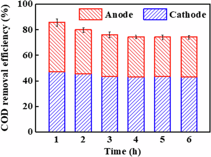
COD removal efficiency of EMR-P.
As mentioned above, the removal of phenol at the cathode and anode involves not only degradation processes but also adsorption processes. The adsorption performance of EMR-P (total adsorption capacity of anode and cathode) for phenol was measured using the adsorption setup (Supplementary Fig. 7), and the phenol removal rate of adsorption process was shown in Supplementary Fig. 8. From Supplementary Fig. 8, the maximum removal of phenol by EMR-P during adsorption alone was about 31.5%, which accounted for 31.8% of the total removal (99.2%). In this process, the maximum adsorption capacities of the cathode and anode for phenol were 32.6 and 26.6 mg g−1, respectively. Apparently, the excellent adsorption property of EMR-P was attributed to both the cathode and anode, which had high adsorption capacities, while the high surface area of CM electrode (BET = 450.7 m2 g–1) played a key role. Moreover, the high-adsorption capacity could facilitate the electrocatalytic and electro-Fenton degradation reaction21.
In addition, the phenol degradation intermediates and their concentration in the anode and cathode permeates (single pass mode) were analyzed by high-performance liquid chromatography (HPLC). To eliminate the interference of incompletely removed phenol on the HPLC detection, the removal of phenol in the EMR-P cathode and anode permeates was increased to 99.96% and 99.91%, respectively, by prolonging the reactor RT to 4.8 min. As shown in Fig. 3, the major intermediates in the cathode permeate (Fig. 3a) and anode permeate (Fig. 3b) were the same, including macromolecular aromatics (hydroquinone, catechol, and p-benzoquinone) and micromolecular acids (maleic acid and oxalic acid). Accordingly, a simple pathway of phenol degradation during EMR-P operation is shown in Supplementary Fig. 95,27,33. First, the reactive radicals generated in EMR-P tend to attack the adjacent or para-positions of phenol electrophilically, resulting in the formation of hydroquinone and catechol. In addition, the major intermediates generated are easily oxidized to p-benzoquinone. Subsequently, further oxidation of the reactive radical disrupts the conjugated structure of the benzene ring in p-benzoquinone, leading to the formation of maleic acid, oxalic acid, and other small acid molecules. Under the above conditions, the mineralization rate (TOC removal rate) of EMR-P cathode and anode permeates were 72.5% and 66.5%, respectively, indicating that phenol and its oxidation intermediates are eventually mineralized into CO2 and H2O.
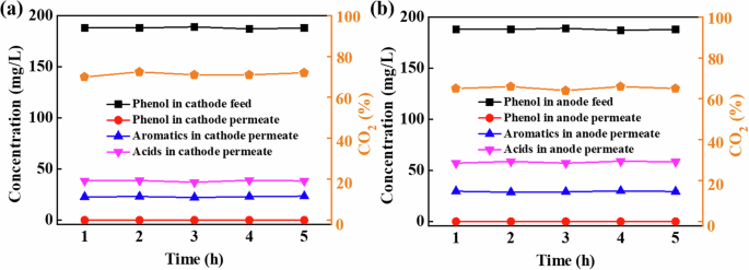
Concentrations of aromatics and acids, as well as mineralization rate in the permeates of a cathode and b anode.
It is worth noting that the concentration of intermediates in the EMR-P anode and cathode permeates differed considerably, as shown in Fig. 3. The concentrations of all intermediates in both permeates remained relatively constant over the 5 h of reactor operation. Specifically, the concentration ranges of aromatics and acids in the cathode permeate were 22.2−23.6 and 37.2−39.1 mg L–1, respectively, which were significantly lower than those in the anode permeate of 28.9−30.1 and 57.2−59.1 mg L–1. Thus, the cathode displayed superior oxidation degradation performance compared to the anode. This may be due to the different species of free radicals at the cathode and anode of EMR-P, which will be discussed further below.
Analysis of reactive radical species in EMRs
To further elucidate the differential mechanisms of phenol removal efficiency and oxidation performance between the anode and cathode, the produced reactive radicals were detected by Electron Spin-Resonance (ESR) analysis and quenching tests. Generally, 5,5-dimethyl-1-pyrroline-N-oxide (DMPO) and 2,2,6,6‐Tetramethyl‐4‐piperidone (TEMPO) are commonly used as the trapping agents for ·OH and ({1atop}{rm{O}}_{2}), respectively. Since it is difficult for DMPO to capture the ·OH adsorbed on the electrode4, the ·OH, and ({1atop}{rm{O}}_{2}) captured by DMPO and TEMPO mainly reflects the proportion in solution. Aeration and mass transfer enhancement leads to the diffusion of reactive radicals in solution, which may result in interactions between anodic and cathodic radicals. Therefore, EMR-C (CM cathode) and EMR-A (TiO2/CM anode) were also analyzed by ESR to represent the case of only cathodic or anodic radicals, respectively. As shown in Fig. 4a, EMR-P generated two characteristic peaks. Specifically, one spectrum consisted of a 1:2:2:1 pattern, which is typical of the DMPO−·OH adduct34,35. The other consisted of a 1:1:1 pattern, which is typical of the TEMPO−({1atop}{rm{O}}_{2}) adduct36. The results indicated that both ·OH and ({1atop}{rm{O}}_{2}) radicals were generated during EMR-P operation. As shown in Fig. 4b, two patterns of 1:2:2:1 (DMPO−·OH signal) and 1:1:1 (TEMPO−({1atop}{rm{O}}_{2}) signal) appeared for EMR-C, but both of them had weaker signal strengths than those of EMR-P. In EMR-A, however, only a 1:2:2:1 pattern (DMPO−·OH signal) appeared, as shown in Fig. 4c. These results indicated that both ·OH and ({1atop}{rm{O}}_{2}) radicals were generated in EMR-C (CM cathode), but only ·OH radicals were produced in EMR-A (TiO2/CM anode). Therefore, EMR-P was more favorable for the production of ({1atop}{rm{O}}_{2}) and ·OH and exhibited higher efficiency compared to EMR-C and EMR-A.
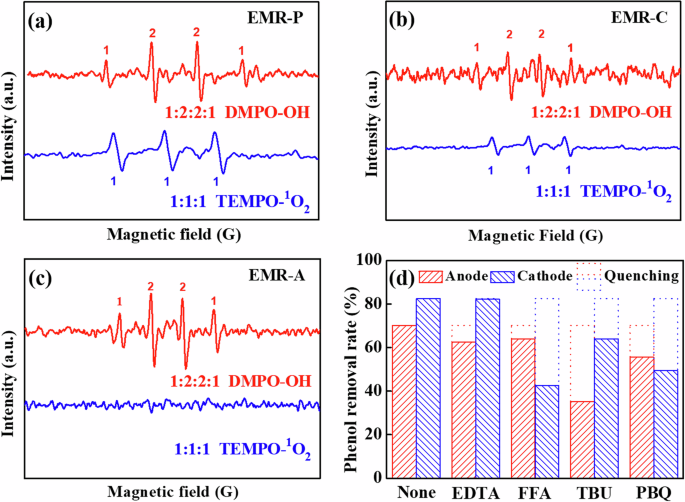
Measured ESR spectra of a EMR-P, b EMR-C, and c EMR-A. d Phenol removal rates at the anode and cathode of EMR-P for different quenching tests.
A series of quenching tests was also conducted to explore the different reactive radical species generated in the anode and cathode of EMR-P, including h+, ({1atop}{rm{O}}_{2}), ·OH, and O2·−, as shown in Fig. 4d4,9,37,38. Under optimum conditions (voltage of 2.1 V, electrode distance of 2.2 cm, RT of 2.4 min, and pH of 2.8), different quenchers were added individually to the feed (188 mg L–1 phenolic wastewater) during the electrochemical degradation process. The dotted open columns in Fig. 4d indicated the proportions degraded by the corresponding oxidants in the quenching tests. Typically, the utilized quenchers for h+, ({1atop}{rm{O}}_{2}), ·OH and O2·− were ethylenediaminetetraacetic acid disodium salt (EDTA-2Na, 100 mM), furfuryl alcohol (FFA, 100 mM), tert-butanol (TBU, 100 mM), and p-benzoquinone (PBQ, 2 mM), respectively. As shown in Fig. 4d, the RP of the anode permeate was 70.2% without the addition of quenchers. With the addition of EDTA, FFA, TBU, or PBQ, the RPs of the anode permeate decreased to 62.5%, 64.0%, 35.2% and 55.7%, respectively. Consequently, this indicates that the anodic oxidation process was mainly influenced by ·OH and partially by ({1atop}{rm{O}}_{2}) and h+. In addition, the RP of the cathode permeate was 82.5% without the addition of any quencher, which decreased to 82.2%, 42.7%, 64.1%, and 49.5% after the addition of EDTA, FFA, TBU and PBQ, respectively. As a result, the cathodic Fenton oxidation process was mainly influenced by ({1atop}{rm{O}}_{2}) and ·OH as well as some O2·−.
Therefore, the oxidation mechanisms at the anode and cathode in EMR-P are significantly different. Noteworthy, the ·OH generated at the anode and cathode was via the electrocatalytic reaction and electro-Fenton reaction, respectively39,40. In addition, More ({1atop}{rm{O}}_{2}) was generated at the cathode, which was attributed to the fact that the O2·− produced by the cathode was the precursor to ({1atop}{rm{O}}_{2}) 41. Furthermore, the mechanism of free radical generation will be explored in detail in the following section.
Synergistic mechanism of EMR-P
Figure 5 shows the possible degradation mechanism of EMR-P based on the ESR analysis (Fig. 4a–c) and systematic quenching tests (Fig. 4d). Remarkably, the introduction of a TiO2/CM anode directly activated h+ oxidation and the reactive TiO2 catalyst at the anode reacted with H2O to mainly produce ·OH radicals (Eqs. (1)–(3)). Additionally, the h+ and e− generated by reactive TiO2 catalyst also produced two other oxidants, O2·− and ({1atop}{rm{O}}_{2}), as shown in Eqs. (4) and (5)9,39.
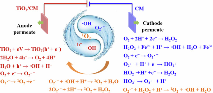
Synergistic mechanism of EMR-P.
Actually, the addition of CM cathode activated the production of more O2·− and OH radicals. These radicals produced differently from those at the anode, with the e− consumed in the reaction being supplied directly by the cathode. Since the cathode can provide a large number of electrons, more O2·− was generated by the cathodic oxygen reduction reaction (Eqs. (4), (6), and (7))42, while ·OH is generated by the electro-Fenton reaction based on the cathodic oxygen reduction (Eqs. (8)–(10))10,24.
Generally, the O2·− generated by the CM oxygen reduction reaction (Eqs. (4), (6), and (7)) can produce ({1atop}{rm{O}}_{2}) under the action of the anode (Eq. (11))41. Moreover, O2·− can also react with H2O2 (Eq. (12)), ·OH (Eq. (13)), and H+ (Eq. (14)) to produce ({1atop}{rm{O}}_{2}). These oxidants might be provided by both anode (·OH) and cathode (·OH and H2O2). Interestingly, the formation of ({1atop}{rm{O}}_{2}) involved the synergistic action of the TiO2/CM anode and the CM cathode of EMR-P.
Although ·OH was primarily generated at the anode and O2·−, as well as H2O2 (which becomes ·OH in the Fenton process), were mainly produced at the cathode, the O2 aeration process required for the cathodic electro-Fenton reaction promoted interactions between the radicals and the electrodes. Specifically, convective and diffusion mass transfer occurred in EMR-P with oxygen aeration, whereas only diffusive mass transfer occurred in EMR-P without aeration. Thus, the diffusion of these oxidants was enhanced by the aeration.
Furthermore, the enhanced mass transfer process of the membrane electrode, which is inherent in EMR-P, also promotes the diffusion of these oxidants4,43,44. Notably, the enhanced mass transfer and diffusion interactions expanded the spatial range of the reactions and facilitated the evolution of free radicals. Compared with the EMR-C and EMR-A systems, the EMR-P system supported a higher free radical evolution efficiency due to the high activity of both membrane electrodes. More importantly, the anode (BET = 430 m2 g–1) was more prone to adsorb reactive radicals diffusing during O2 aeration in the system and the mass transfer process of the membrane compared to the Ti plate electrode (BET = 3 m2 g–1), which contributed to the production of more ({1atop}{rm{O}}_{2}).
The oxidation performance of the anode is inferior to that of the cathode. This is due to the fact that ·OH, O2·− and ({1atop}{rm{O}}_{2}) play an important role in the phenol degradation process. First, ·OH (2.8 V) is strongly oxidizing, but has a limited diffusion distance due to its short lifetime (<10−6 s). Thus, ·OH produced by heterogeneous catalysts (TiO2 particles) at the anode is difficult to diffuse into solution45. However, the ·OH generated by the Fenton reaction at the cathode with homogeneous catalysts (Fe2+ solution) is in the solution and, therefore, more likely to encounter and react with pollutant molecules. Second, regarding O2·− generated at the cathode, its oxidation potential (2.4 V) is weaker than that of ·OH, but it has a longer lifetime (10−6 s), so its diffusion distance is not as limited. This facilitates the diffusion of O2·− into the solution (solid-liquid interface) where it can participate in degradation reactions or generate more ({1atop}{rm{O}}_{2}). Finally, ({1atop}{rm{O}}_{2}) (2.2 V) has a weak oxidation potential and a relatively long lifetime (2 × 10⁻⁶ s), and therefore a relatively long diffusion distance, which enables it to diffuse into solution and oxidize pollutant molecules throughout the system46. Obviously, the degradation efficiency of the whole system is higher than that of the electrode surface only. Both O2·− generated by the cathode and the ({1atop}{rm{O}}_{2}) generated by the cathode and anode can enhance the degradation efficiency of EMR-P. While the generation of these free radicals is driven by a series of electrochemical reaction, as shown in Eqs. (8)–(10). In brief, the excellent phenol removal performance of EMR-P was attributed to the anodic electrocatalytic oxidation degradation, cathodic electro-Fenton oxidation degradation, and the good adsorption property of CM electrodes with a high BET-specific surface area.
In conclusion, a flow-through EMR-P with two permeates and without an ion exchange membrane was successfully constructed for phenolic wastewater treatment using a self-supported CM as the cathode and TiO2/CM as the anode. As a result, the fabricated EMR-P exhibited a high removal rate for phenol (99.2%) and COD (93.9%). Moreover, the EC of the EMR-P was lower than 0.43 kWh kgCOD–1. Remarkably, the excellent performance of the EMR-P was attributed to the combined action of anodic electrocatalytic oxidation, cathodic electro-Fenton oxidation, and high-adsorption properties of CMs. Noteworthy, the high-adsorption properties of CM electrode and production of ({1atop}{rm{O}}_{2}) at both the cathode and anode of EMR-P played a crucial role in the removal of COD. The cathode contributed more to COD removal (59.0%) than did the anode (41.0%). In conclusion, the efficient and low-EC EMR-P, which contains a pair of CM electrodes, offers an attractive option for wastewater treatment.
Methods
Materials
Coconut shell AC was obtained from Gongyi Miaoyuan Water Treatment Materials Co., Ltd (China). Phenolic resin 382 (99%), polyvinyl butyral (PVB; 97%), and methylcellulose (99%) were all purchased from Shanghai Yingjia Co., Ltd (China). The flat-sheet porous Ti plate (37 × 37 × 2 mm3) with an average pore size of 3.5 μm, porosity of 26.8%, and thickness of 2.7 mm, was acquired from Xi’an Siyu Metal Material Technology Co. All other chemicals (analytical reagents) were purchased from Tianjin Kermel Co., Ltd. (China) and used directly without further treatment.
Preparation of CM and TiO2/CM
AC (325 mesh) and phenolic resin were the main raw materials for CM. The preparation and characterization of self-supporting CM have been reported in our previous work21. As shown in Supplementary Fig. 10, the raw materials were first mixed with PVB and methyl cellulose in ethanol. Subsequently, this mixture was then molded into a plate and calcined at 1150 °C for 3 h under an H2 atmosphere to form and improve the electrochemical activity of CM21. Finally, the CM electrode (37 × 37 × 5 mm3) was obtained with an average pore size of 34 nm, porosity of 42.3%, BET surface area of 450.7 m2 g–1, bending strength of 2.9 MPa and electrical conductivity of 1705 S m–1.
Additionally, TiO2 nanoparticles loaded CM electrode (TiO2/CM) was fabricated by a previously described method (Supplementary Fig. 10)9. Typically, tert-butyl titanate was used as the precursor for TiO2 sol-gel. Specifically, the CM was first pre-treated with concentrated nitric acid and then cleaned until neutral pH. After drying in air, the pre-treated CM was immersed in a TiO2 sol and then dried. Finally, the TiO2/CM electrodes with a TiO2 loading rate of 14 wt.% were prepared by sintering the coated film in a tube furnace under an N2 atmosphere.
Three EMRs with the CM electrodes
The schematic diagram of the flow-through EMR system is shown in Fig. 1a and its photograph is shown in Supplementary Fig. 11. In addition, Fig. 1b–d exhibit three EMRs using different assemblies of electrode pair. In detail, an EMR with a pair of CMs (EMR-P) as the working electrodes is shown in Fig. 1b. In EMR-P, one CM served as the cathode, and one TiO2/CM was the anode, providing a pair of electrodes with an adjustable spacing distance (10−30 mm), connected in parallel to a direct current power supply. Moreover, the electrode distance could be adjusted by changing the thickness of the chamber components between the anode and cathode, as shown in Supplementary Fig. 12. In the treatment process, wastewater flowed from the feed tank into the chamber between the anode and cathode of the reactor. Then, part of the wastewater flowed through the cathode (CM) via a suction pump, and the permeate from the cathode was collected from the top efflux on the right side of the reactor. The other part of the wastewater flowed through the anode (TiO2/CM) via another suction pump, with the permeate from the anode being collected from the top efflux on the left side of the reactor.
For comparison, two additional EMRs, each with only one CM working electrode, were also assembled, as shown in Fig. 1. Figure 1c shows EMR-C, where CM as the cathode and a Ti plate as the anode, with only cathode permeate flowing out of the top on the right side of the reactor. Figure 1d shows the EMR-A, which consists of a TiO2/CM as an anode and a Ti plate as the cathode, with only anode permeate collected from the top efflux on the right of the reactor. Notably, all operating parameters for EMR-C and EMR-A were the same as for EMR-P. Moreover, the RT of the reactors could be precisely controlled by adjusting the speed of the peristaltic pump, and a consistent RT was maintained in three EMRs. Additionally, the oxygen aeration unit was set up in the chamber component between the anode and cathode, and the reactor was aerated at a rate of 100 mL min–1 (99.9%, O2).
Phenolic wastewater treatment
In synthetic phenolic wastewater, 188 mg L–1 phenol and 15 g L–1 Na2SO4 were utilized as the organic pollutant and electrolyte, respectively. The concentration of phenol pollutants selected in this study represents the composition of some specific industrial effluents, especially those from chemical synthesis and refining industries5,39. Specifically, 30 mg L–1 of FeSO4 was added to the system as a Fenton catalyst. Among them, the Fe2+ catalyst concentration was selected as shown in Supplementary Fig. 13.
The intermediates of phenol degradation and their concentrations were detected by HPLC (HP1200, Agilent) with an AQ C-18 column5. The eluent was a 50:50 (v/v) mixture of acetonitrile and water at a flow rate of 0.8 mL min–1 for the detection of aromatic intermediates, and the injection volume was 20 μL at a detection wavelength of 270 nm. Moreover, the eluent was a mixture of 88:12 (v/v) phosphate buffer solution (0.1%) and methanol at a flow rate of 0.5 mL min–1 for the detection of acidic intermediates, and the injection volume was 10 μL at a detection wavelength of 210 nm. And the mineralization rate (%CO2) is then calculated using Eq. (15).
Here, TOCF and TOCP are the TOC values in the feed and permeate of the anode or cathode (mg L–1), respectively. PhenolF is the phenol concentration in the feed (mg L–1).
Chemical oxygen demand (COD) and total organic carbon (TOC) were measured using a portable spectrophotometer (DR2800, Hach) and TOC tester (5050 A, Shimadzu), respectively. Notably, the COD removal rate (RCOD) of EMR-P under single pass mode was calculated using Eq. (16), and the TOC and phenol removal rate (RP) were calculated in the same way.
Here, CODF, CODP-A, and CODP-C are the COD values of the feed; anode permeate and cathode permeate (mg L–1), respectively. VF, VP-A, and VP-C refer to the volumes of the feed, anode permeate, and cathode permeate (L), respectively. Wherein, the VP-A represents zero in EMR-C and VP-C stands for zero in EMR-A.
The RCOD of EMR-P under cycle mode was calculated according to Eq. (17), and RP under cycle mode was calculated in the same way.
Here, COD0 and CODt are the COD values of the initial and running of t time in EMR system, respectively (mg L–1).
The EC was expressed as Eq. (18)5.
Here, U is the operating voltage (V), I refers to the current intensity (A), and Δt represents the time (s).
The COD removal efficiency of EMR-P cathode and anode was calculated by the following Eq. (19).
Here, CODP refers to the COD value of anode permeate or cathode permeate, and the corresponding VP is the volume of anode permeate or cathode permeate.
Adsorption performance measurement
The adsorption performance of EMR-P for phenol was measured using the adsorption setup (Supplementary Fig. 7). In the adsorption process, the phenolic wastewater (188 mg L–1) flowed from the feed tank into the chamber between the anode and cathode of the adsorption setup. Then, part of the wastewater flowed through the cathode (CM) via a suction pump, and the permeate (after adsorption of cathode) from cathode was collected from the top efflux on the right side of the reactor. The other part of the wastewater flowed through the anode (TiO2/CM) via another suction pump, with the permeate (after adsorption of anode) from the anode being collected from the top efflux on the left side of the reactor. Finally, both the permeates from cathode and anode flowed back to the feed tank. The adsorption process was in a cycle mode during operating, and the adsorption removal rate of phenol can be calculated by using the same way as Eq. (17).
Free radical measurement
Two types of strategies were employed to detect the production of reactive species4. Electron spin-resonance (ESR) tests were first performed to detect ({1atop}{rm{O}}_{2}) and ·OH using an ESR spectrometer (JES-FA200, Japan). In addition, 2,2,6,6‐Tetramethyl‐4‐piperidone (TEMPO) and 5,5-dimethyl-1-pyrroline-N-oxide (DMPO) were used as capture agents for ({1atop}{rm{O}}_{2}) and ·OH, respectively. Remarkably, the feed solution contained 120 mmol L–1 of trapping agent (TEMPO or DMPO) and 15 g L–1 of Na2SO4. Furthermore, ESR spectra were recorded with the following parameters: a central magnetic field of 3290 G, microwave power of 2.0 mW, sweep width of 100 G, modulation frequency of 9.89 GHz, and room temperature.
A series of quenching tests were conducted to explore the generation of different reactive species including h+, ({1atop}{rm{O}}_{2}), ·OH, and O2·−4. During the electrochemical degradation process, different quenching agents were added individually to the feed (188 mg L–1 phenolic wastewater). Noteworthy, the quenching agents for h+, ({1atop}{rm{O}}_{2}), ·OH and O2·− were ethylenediaminetetraacetic acid disodium salt (EDTA-2Na, 100 mM), furfuryl alcohol (FFA, 100 mM), tert-butanol (TBU, 100 mM) and p-benzoquinone (PBQ, 2 mM), respectively.


Responses