Structural flexible magnetic films for biometric encryption and tactile interaction in wearable devices
Introduction
Human hand skin contains fingerprints and tactile receptors with distinct functions (Fig. 1a). Fingerprints enable authentication and identification, while tactile receptors sense external stimuli such as pressure, sliding, and contact. Artificial skin aims to imitate human skin’s capabilities. However, integrating these functions remains a significant challenge, yet offers immense potential for applications in human-computer interaction, electronic skin, and robotics (Fig. 1b).
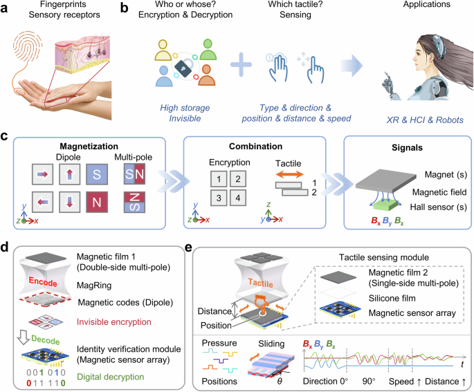
a Structure and functions of human fingers. b Requirements and applications for encryption and tactile perception. c Magnetization structures and their combinations generate different signals. d Magnetic encryption and decryption: this process involves using dipole magnetic arrays for encryption and the corresponding decryption via a Hall sensor array. e Tactile sensing and recognition: a demonstration of sliding and pressure decoupling mechanisms, including detecting different positions, directions, distances, and speeds.
In previous research, encryption functions have primarily relied on material properties, such as magnetic1 and thermosensitive2, or reprogrammable mechanical structures3,4,5 (Supplementary Table 1). Magnetic encryption has the advantage of invisibility, as demonstrated by Alapan et al., who created invisible patterns on CrO2 flexible films6. However, observing the magnetic patterns typically requires costly equipment. There remains a need for an invisible encryption method that is both cost-efficient and easy to decode. On the other hand, pressure sensors utilize techniques such as capacitive7,8,9,10, resistive11,12,13,14, piezoelectric15,16,17,18, piezoresistive19, optical20, and magnetic21,22,23,24 methods, while sliding detection involves triboelectric25,26,27, capacitive28, resistive29, and magnetic sensors30,31,32. Pressure and sliding detection principles partially overlap, and multiple tactile perceptions can be achieved. Although multi-tactile sensors capable of signal decoupling hold promise, they often face challenges (Supplementary Table 2). Few studies have comprehensively addressed the decoupling of tactile types, direction, position, distance, and speed. A unified approach that enhances encryption and tactile sensing could lower costs and improve integration.
Herein, we propose a method that integrates information encryption and tactile perception using flexible magnetic films (Fig. 1c). This approach utilizes magnetization structures and their combinations to generate unique magnetic field components (Bx, By, Bz), which are detected by Hall sensors. The magnets are categorized as dipolar or multipolar. Simulations and experiments demonstrate that dipole magnets exhibit the strongest magnetic field component along their magnetization direction, whereas multipolar magnets show periodic variations. Leveraging these characteristics, dipole magnetic arrays are utilized for encryption, while multipolar magnets enable tactile sensing. The principles of encryption are as follows: each of the six dipole magnetic types is assigned a three-bit code based on its field components. An n × n magnetic pixel array encodes 6n × n types of information. This method is invisible, highly secure, information-rich, and cost-effective. Highly operable and convenient decryption is achieved by detecting the magnetic field through a Hall sensor array. The principles of tactile sensing are as follows: an axial multipole magnetic film is combined with a Hall sensor PCB to form a tactile sensing module. Pressure-induced deformation alters the magnetic field, enabling detection from 0.5 kPa to 25 kPa. Force decoupling is achieved at five positions by coordinating the positional relationship between magnetic poles of opposite polarity and Hall sensors. Additionally, superimposing the magnetic fields of two multipole magnetic films allows decoupled detection of sliding in different directions (parallel and perpendicular), distances (0–2.5 mm), and speeds (5–25 mm/s). Based on these principles, we have developed a magnetic ring (MagRing) to demonstrate this integrated approach. This approach enhances information security and offers tactile sensing methods for human-computer interaction and robotics.
Results
Concepts and design principle
Our method utilizes magnetization structures and combinations to generate magnetic field signals detected by three-axis Hall sensors (Fig. 1c). Based on the number of magnetic pole pairs, we differentiate between dipole and multipolar magnetization. Dipole magnetization generates six distinct modes along the three axial directions, with the surface magnetic field being most pronounced along the magnetization axis. Using this property, we combine these six basic magnetic codes to create an encrypted array, which enhances the security of the information by remaining invisible. Moreover, adjusting the magnetic film combinations makes a programmable encryption array achievable. Each encryption unit’s magnetic field components are read by the Hall sensor array and converted into digital codes. Multipolar magnetization features staggered and periodically arranged magnetic poles, resulting in periodic magnetic field distribution. This characteristic is commonly utilized in magnetic encoders for position and speed detection. By strategically placing Hall sensors under opposing magnetic poles, we effectively decouple pressure at various locations. Additionally, stacking two multipolar magnetized films along the thickness direction forms a coupled magnetic field. The superimposed magnetic signal depends on the number of magnetic poles, distance, relative motion, and speed between the two films.
Building on these principles, we integrate both functionalities into a wearable magnetic ring (MagRing) and design corresponding signal modules for demonstration. The MagRing features a 2 × 2 dipole magnetic code array and a multipolar magnetic film. The identity verification module is a PCB with Hall sensor chips (MLX90393) that decrypts the magnetic code information into digital codes (Fig. 1d). Meanwhile, the tactile sensing module consists of a striped multipolar magnetic film, a silicone rubber layer and a PCB (Fig. 1e). It detects pressure at different positions and tracks the relative movement of the MagRing. The design of the magnetization structure allows us to integrate both functions into a single, wearable, and standalone MagRing, with modules that can be flexibly held or assembled.
Magnetization modes and signals
The magnetic field is a vector field defined by both direction and magnitude. The static magnetic field depends on the structure and magnetization profile of the magnetic material33,34,35. We propose generating magnetic field signals by controlling the magnetization direction and the number of magnetic pole pairs in flexible NdFeB films. The spatial magnetic field distributions differ for axial dipole (Fig. 2a), radial dipole (Fig. 2b), and axial multipolar (Fig. 2c) magnetization.
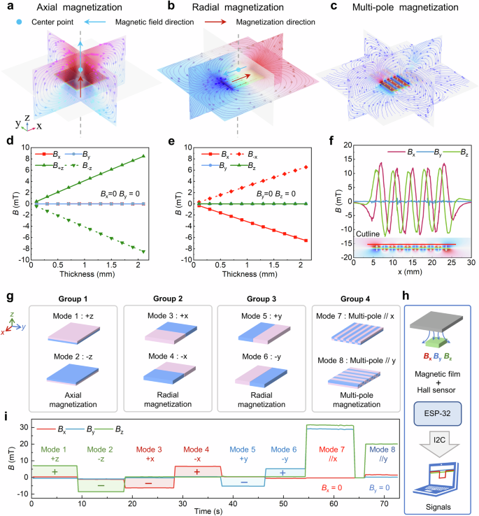
a Magnetic field of an axial dipole magnet. b Magnetic field of a radial dipole magnet. c Magnetic field of a multipole magnet. d Relationship between magnetic field and thickness at the center of the axial magnet. e Relationship between magnetic field and thickness at the center of the radial magnet. f Magnetic field distribution along a cutline of a multipole magnet. g Categories of magnetization modes. h Method for measuring magnetic field signals. i Magnetic field signal data.
The dipole magnet has one pair of magnetic poles. For axial magnetization, the poles are aligned along the thickness of the magnetic film, whereas for radial magnetization, they are perpendicular to it. The magnetic field at the center of the surface reaches its maximum magnitude along the magnetization direction (Supplementary Text, Formulas (1)–(6))36. COMSOL Multiphysics simulates the relationship between the magnetic field and thickness at the center of the axial (Fig. 2d) and radial magnetization (Fig. 2e), with the magnetic film dimensions set at 20 mm in length and width. The simulations yield the following conclusions: (1) At the center above the magnetic film, the magnetic field component along the magnetization direction is the strongest, while the components in the other two directions are zero. (2) The strongest magnetic field component positively correlates with the film thickness; thicker films generate stronger magnetic fields. (3) The surface magnetic field’s magnitude is the same for opposite magnetization directions along the same axis. (4) For z-axis magnetization, the strongest magnetic field component is aligned with the magnetization direction. Still, for radial magnetization, the strongest surface magnetic field component is opposite to the magnetization direction.
The axial multipole magnet contains more than one pair of magnetic poles, creating a staggered magnetic field alternating North and South poles along the x-axis or y-axis. We develop a simulation model of a 10-pole magnetic film and draw a cutline above the surface. The magnetic field components along this cutline show periodic curves in the direction of the pole arrangement (Fig. 2f). The Bx curve is axially symmetric, and the Bz curve is centrally symmetric. Theoretical models and formulas are provided in the supplementary material (Supplementary Text, Formulas (7)–(9))36.
We categorize the magnetization modes into four groups (Fig. 2g): z-axis axial magnetization (mode 1: B+z; mode 2: B-z), x-axis radial magnetization (mode 3: B+x; mode 4: B-x), y-axis radial magnetization (mode 5: B+y; mode 6: B-y), and axial multipole magnetization (mode 7: Bmp//x; mode 8: Bmp//y). The magnetic film measures 2 cm × 2 cm × 1 mm in the experiment. The Hall sensor detects the magnetic field components (Bx, By, Bz) for these eight magnetization modes (Fig. 2h) and presents the signals (Fig. 2i). Groups 1, 2, and 3 each contain a pair of opposite signals. Group 4 ensures one horizontal direction signal is zero (Bx or By = 0), with assembly accuracy affecting the other two signals. Dipole magnets produce the strongest field in a specific direction, making them suitable for encoding tactile information. The periodic and directional magnetic fields of multiple poles enable tactile recognition.
Magnetic encryption and decryption
The magnetic encryption and decryption method is illustrated in Fig. 3a. Three groups of dipole magnetic films serve as the basic codes, which are assembled into a programmable magnetic code array. The magnetic poles within the flexible magnetic film are invisible, enhancing information security. The storage density is defined as 6n × n, where the array size is n × n. Decryption is based on the magnitude and direction of the magnetic field, as outlined in Table 1. The components Bx, By, and Bz are converted into three-digit binary numbers, with the component exhibiting the highest absolute value designated as the judgment bit. Positive values yield a judgment bit of 1, while negative values yield 0. The other two digits are the complements of the judgment bit. Simulation results confirm that the magnetic field coupling between adjacent magnetic films does not affect the decryption rule (Supplementary Figs. 1–4). The magnetic film array is aligned with the Hall sensor array to decrypt the magnetic codes to digital ones.
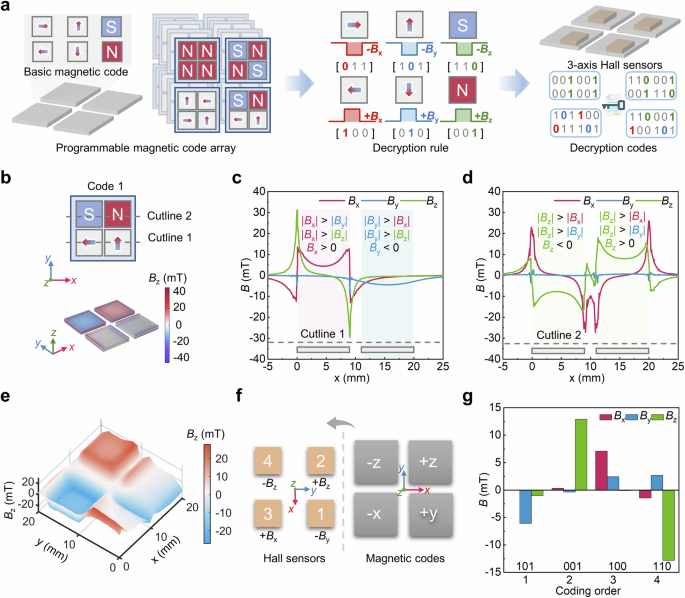
a Magnetic encryption and decryption principle and process. b Simulation model of magnetic encoding combination. c Magnetic field component trend at cutline 1. d Magnetic field component trend at cutline 2. e Magnetic field measurements. f Correspondence between magnetic films and Hall sensors. g Magnetic field signal and encryption results.
A 2 × 2 array is an example of simulation and experiment verification. One of the simulation models is shown in Fig. 3b. Each magnetic film measures 9 × 9 × 1 mm, with a distance of 2 mm between films. The magnetic fields above the magnetic film array at the two auxiliary lines, cutline one and cutline two are shown in Fig. 3c, d. The array combination does not affect each basic magnetic code’s maximum absolute value and direction. In the experiments, the array magnetic films are placed in array-shaped grooves, and the distribution of Bz is measured (Fig. 3e). The array magnetic film is aligned with 2 × 2 Hall sensors. After the coordinate system transformation (Fig. 3f), the strongest values detected in order are −By, +Bz, +Bx, and −Bz (Fig. 3g). They are converted to codes: [101, 001, 100, 110]. The corresponding decimal code is 5146.
Magnetic tactile perception
The staggered magnetic pole configuration in the multipolar magnetic film facilitates tactile perception. The tactile sensing module has three layers: a single-sided multipole magnetic film, a silicone film, and a circuit board with Hall sensors. The dimensions and fit are shown in Fig. 4a. The magnetic film measures 20 × 20 × 1 mm, with a 2 mm pole pitch and ten magnetic poles. Hall sensors 1 and 2 are positioned beneath the South Pole, sensors 4 and 5 beneath the North Pole, and sensor 3 between the two magnetic poles. By optimizing the magnetic pole structure and aligning it with the Hall sensors, we minimize algorithm dependence and achieve pressure decoupling at five locations (Fig. 4b). Pressing areas 1, 2, 4, and 5 increases the absolute value of Bz, and pressing area 3 enhances the absolute values of By and Bz. The five three-axis Hall sensors produce 15 signal curves, with six curves (Bz1, Bz2, Bz4, Bz5, By3, and Bz3) effectively decoupling pressures at five locations. The value of Bx3 is close to zero, serving as an indicator of assembly accuracy. The three-axis test system evaluates the performance of the tactile sensing module (Supplementary Fig. 5, Supplementary Movie 1), showing a response time of 0.31 s, a relaxation time of 0.31 s (Fig. 4c), a minimum resolution of 0.2 N (Fig. 4d), and 1000 repeatability tests (Fig. 4e).
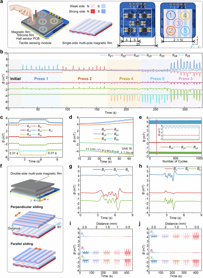
a Tactile sensing module composition and dimension. b Decoupling of pressing positions. c Response and recovery times. d Micro pressure detection. e Repeatability. f Superimposition of two magnetic films for decoupled sliding. g The signal of 90° sliding. h The signal of 0° sliding. i 90° sliding with different distances. j 0° sliding with different distances.
The sliding state is determined by detecting changes in the superimposed magnetic field of two magnetic films (Fig. 4f, Supplementary Movie 2). The double-sided magnetic film can be assembled with any object, allowing the tactile sensing module to detect its movement state. The contact between the double-sided magnetized film and the non-magnetized side of the single-sided magnetized film prevents excessive magnetic force from hindering smooth contact sliding. When the magnetic poles of the two films are oriented at 90°, this is referred to as perpendicular sliding; when they are aligned at 0°, it is termed parallel sliding. During perpendicular sliding, the periodic magnetic field of the double-sided magnetic film along the x-axis and z-axis combines with the initial magnetic field component of the single-sided magnetic film to produce a periodic signal, while the y-axis signal shows no significant fluctuations (Fig. 4g). In contrast, during parallel sliding, the periodic magnetic field of the double-sided magnetic film along the y-axis and z-axis combines with the initial magnetic field of the single-sided magnetic film, resulting in a periodic signal with no notable fluctuations in the x-axis signal (Fig. 4h). This magnetic field coupling method can also be extended to non-contact sliding detection, surpassing the sensory capabilities of human skin. The signals for perpendicular and parallel sliding at various distances are presented in Fig. 4i and Fig. 4j, respectively, showing that the absolute value of signal fluctuations increases as the distance decreases. In addition, the period decreases when the sliding speed increases from 5 mm/s to 25 mm/s (Supplementary Fig. 6).
Demonstrations
The flexible encrypted magnetic pole array and multipolar magnetic film are integrated into a ring for demonstration. This double-sided magnetic ring and its corresponding module are used for identity recognition and interactive perception. The user aligns the encryption surface with the identity verification module, and the array of Hall sensors detects the magnetic field signals (Fig. 5a). The computer interface unlocks once the identity is successfully matched (Supplementary Movie 3). The second encryption magnetic code and decryption is [011, 001, 100, 001] (Supplementary Fig. 7). The invisible array encryption system verifies unique identity information, ensuring secure interactions.
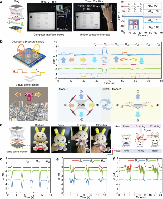
a Identity encryption and tactile information recognition. b Demonstration of force decoupling in controlling a virtual drone. c Demonstration of force and slide decoupling. d Pressure signals. e 0° sliding signals. f 90° sliding signals.
The tactile sensing module decouples the pressure at five distinct positions. This functionality is demonstrated through virtual drone interaction (Fig. 5b, Supplementary Movie 4). The corresponding magnetic field component changes are identified upon pressing, enabling control over the virtual drone’s movements. The drone can perform actions in two distinct modes, comprising eight maneuvers. In the first mode, pressing area 1 moves the drone forward, area 5 moves it backward, area 2 turns it left, and area 4 turns it right. Pressing area 3 toggles between the two modes. In the second mode, pressing area 1 makes the drone ascend, area 5 makes it descend, area 2 executes a fast left turn, and area 4 performs a fast right turn.
The tactile sensing module is capable of detecting the relative sliding of the multipolar magnetic film surface on the ring. Additionally, since the magnetic fields between the two magnetic films can couple without physical contact, the tactile sensing module is suitable for embedding within objects. This feature is demonstrated in a virtual reality pet game, where the module is placed beneath the fabric of a rabbit toy (Fig. 5c). When pressure signals (Fig. 5d), 0° sliding (Fig. 5e), and 90° sliding (Fig. 5f) are detected, the virtual pet responds accordingly. Pressure and sliding signals are decoupled. Pressing causes the pet to jump, 0° sliding increases its emotional value, and 90° sliding makes the pet sit down and rest (Supplementary Movie 5). This system shows great potential for applications in humanoid and care robots.
Discussion
In this study, we propose a solution to use magnetization features for tactile encryption and multi-sensory tactile decoupling and integrate the two functions on a wearable ring. The identity verification and tactile sensing modules are designed for decoding and decoupling. We expand functions in three areas: (1) Compared with sensors of the same type (Supplementary Table 3), it achieves sliding and pressure decoupling. The slide sensing covers the detection of contact and non-contact, two vertical directions, different distances (0–2.5 mm), and speeds (5–25 mm/s). (2) Pressure decoupling in five positions. (3) An invisible identity encryption and decoding method are proposed, which enhances the degree of security protection and realizes 6n × n kinds of identity encoding.
To further enhance system performance, future work will focus on the following areas: miniaturizing Hall sensors and improving the magnetism of magnetic films to increase sensitivity and resolution. Advanced semiconductor technologies, such as MEMS, enable Hall sensors to achieve high precision, compact size, low power consumption, greater material versatility, and adaptability to more flexible scenarios. Micro-Hall sensors could be up to 10,000 times smaller than the commercial sensors used in this study, potentially achieving higher-density encryption and superior tactile resolution. Such miniaturization would enable more compact systems, which are ideal for wearable electronics and other space-constrained devices, paving the way for multifunctional flexible electronics integrating encryption and haptic sensing. Additionally, flexible magnetic tactile sensors excel at detecting subtle pressures and non-contact sensations. Further sensitivity and resolution improvements could be achieved by strengthening the magnetic films and optimizing the surface magnetic poles’ arrangement.
In addition to the applications demonstrated in this article, we aim to further integrate magnetic encryption with tactile systems and extend their use to other wearable devices, intelligent prostheses, and robots. For robotics, this technology could enable secure encryption to control device access and prevent unauthorized tactile interactions. Moreover, it could be applied to humanoid patient robots to train medical staff in operation precision. Overall, this approach holds significant potential in information security, human-computer interaction, robotics, and beyond.
Methods
Fabrication of magnetic films
The method for preparing the magnetic film is shown in Supplementary Fig. 8. Dragon Skin™ 10 NV (Smooth-On, Inc, Macungie, PA) is a versatile addition-cure silicone rubber with low viscosity and high performance. NdFeB is chosen due to its excellent magnetic properties, including high remanence and coercivity. These properties are essential for stable and strong magnetization, which is critical for our encryption and tactile sensing applications. Dragon Skin component A, magnetic powder (NdFeB, average diameter: 38 μm; LW-N 12-9, Guangzhou Xinnuode Transmission Parts Co., Ltd.), and component B were combined in a container, maintaining a mass ratio of 1:3:1. Subsequently, thorough mixing for 3 min ensured uniform distribution. The mixture was poured into a slot-shaped mold with a thickness of 1 mm. Finally, after curing at room temperature for around 75 min, we peeled it off and cut it into multiple 2 × 2 cm or 9 × 9 mm squares with a leather cutting machine.
Magnetization
The magnetization process aims to orient the magnetic poles in a specific direction. Axial magnetization involves magnetizing along the thickness direction of a magnet. In the case of a cuboid-shaped magnet measuring 20 × 20 × 1 mm, the magnetic poles are located on the larger rectangular faces. On the other hand, diametrical magnetization refers to magnetizing an object through its diameter or length. The magnetic poles are positioned on the narrow side surfaces for the square magnetic film. During the impulse magnetization process facilitated by the magnetizer (MAT-3030, Shenzhen Jiujuok Industrial Equipment Co., Ltd.), the capacitor underwent charging following rectification. Subsequently, the electrical energy stored in the capacitor was promptly discharged into the magnetizing fixture. This fixture generated a pulsed magnetic field (3 T) during the rapid flow of a strong current through it. Consequently, the magnet within the coil was magnetized (Supplementary Fig. 9).
An axial multipole magnet has more than one magnetic pole along its axial direction, and there are two primary types of axial multipole magnetization: single-side and double-side. The multipole plane magnetizer (Hangzhou Xinci Technology Co., Ltd.), equipped with ten poles, was utilized for magnetizing both types (Supplementary Fig. 10). This magnetizer featured a pair of magnetized fixtures. The lower magnetized fixture was energized during the magnetization process to accomplish single-sided magnetization. Simultaneously, the upper and lower magnetized fixtures were energized to achieve double-sided magnetization.
Characterization
The magnetic film’s performance characterization mainly included magnetic and mechanical properties. The hysteresis loops (Supplementary Fig. 11) were characterized by a physical property measurement system PPMS (PPMS-9T, Quantum Design). The surface magnetic field intensity was measured by an automatic surface magnetic field testing system (TY2100, TUNKIA, China). It scans Bz on a plane (Supplementary Fig. 12), and its accuracy reaches ten μT. Young’s modulus was measured by a universal material testing machine (Z020, ZwickRoell, Germany). The tensile modulus of the magnetic film is 1.03 MPa (Supplementary Fig. 13).
Fabrication of elastomer
The silica gel layer between the magnetic film and the circuit board increases the deformation. We mixed and stirred the A and B reagents of Ecoflex-0010 and solidified to obtain a transparent film of 2 cm × 2 cm × 1 mm.
Assembly
The tactile sensing module has a three-layer structure: the magnetic film on top, the silicone layer in the middle, and the Hall sensor circuit on the bottom. The silicone film was glued to the circuit board during assembly, and then the magnetic film was stuck on top.
Simulation model
Comsol Multiphysics simulated the magnetic field. The magnetization direction of the dipole magnetic film was set along the coordinate axis. We divided the 20 × 20 × 1 mm multipole magnetic film into smaller cuboids of size 2 × 20 × 1 mm. Each cuboid had a magnetization direction along the thickness direction, resulting in alternating North and South magnetic poles.
Signal detection
The MLX90393 chip (MLX90393ELW-ABA-011-SP) detected changes in the three-axis magnetic field component. The PCB with 5 MLX90393 chips achieved resolution of the direction of sliding objects.
Responses