Dendrite corrosion of 316L stainless steel weld joint in NaCl–MgCl2 molten salt loop
Introduction
MSR is a promising Generation-IV reactor concept dedicated to advancing next-generation, low-cost, carbon-free nuclear technology to help meet global emissions-reduction targets and provide reliable power1. Due to the potential advantages of molten salts in terms of safety, efficiency, and sustainable fuel cycle, there is a long-standing and growing interest in the study of MSR2. Among all the MSR concepts, molten salts are being considered worldwide as fuel-bearing salt with fissile material dissolved in and/or as a coolant in conjunction with solid fuel1,3. Lots of different kinds of salts have been proposed for use in MSR including LiF–BeF2, LiF–NaF–KF, ZrF4–NaF–KF, ZrF4–KF, and NaF–BeF2 eutectic mixtures, etc.4. Chloride salts have some attractive features compared with fluorides. For instance, actinide trichlorides form lower melting point solutions and have higher solubilities for actinides such that they can contain significant amounts of transuranic elements. Therefore, in addition to fluoride salts, chloride salts are under consideration for use in MSR by MSR design companies such as TerraPower LLC and Moltex LLC. Among them, NaCl–MgCl2 eutectic salt is one of the most popular based-salt candidates proposed as the coolants.
One major concern in the implementation of the MSR is the structural material corrosion since the protective oxide layer of alloys relied upon for corrosion resistance in most oxidative environments is rendered unstable in molten salts5. To solve this issue, lots of work has been performed regarding the molten salt corrosion-resistant alloy development6, alloy’s corrosion resistance evaluation in molten salt environments7,8,9,10, and molten salt corrosion mitigation method exploration3,11. However, due to the complexity and high cost of high-temperature corrosion experiments at flow conditions, most of these molten salt corrosion studies were performed at static conditions. The molten salt corrosion study at flow condition can be dated back to the Aircraft Nuclear Propulsion programme at Oak Ridge National Laboratory in the 1950s12,13,14. There has been a rising interest in studying the corrosion behaviours of alloys in molten salt loops in recent years. For instance, Raiman et al.15 studied the corrosion of 316H stainless steel samples exposed to LiF–NaF–KF (FLiNaK) molten salt thermal convection loop. The corrosion behaviour of GH3535 alloy in LiF–BeF2 (FLiBe) molten salt thermal convection loop was investigated recently as well16. The thermal gradient corrosion studies of different alloys in NaCl–MgCl2 eutectic molten salt were also reported in previous literatures17,18.
The welding technique has been widely used to connect structural components such as pipes and tanks in nuclear reactors19. The corrosion behaviours of the welds and their parental metals in the same environment are usually different, with the welds often showing relatively higher corrosion rates. Therefore, it is necessary to understand the corrosion performance of structural alloys and their weld joints in molten salts for supporting the deployment of MSR. As an American Society of Mechanical Engineers (ASME) code-certified alloy for high-temperature systems, 316L stainless steel is a candidate structural alloy for MSR because of its low costs and excellent mechanical properties20. In the present study, the corrosion behaviours of 316L stainless steel and its welds in NaCl–MgCl2 eutectic molten salt thermal convection loop were studied. Unlike the corrosion studies performed in the molten salt loop as reported by previous studies15,16 in which the corrosion samples were hung inside the loop, the corrosion specimens in this study are the loop itself, i.e. the tubes to build the loop17. The loop was naturally circulated for about 260 h and the corrosions of 316L stainless steel and its welds created by orbital welding were studied through the post-material characterizations. This study will provide guidance and evaluation on the alloy welding utilized in the deployment of MSR.
The present study focuses on the comparison study of 316L stainless steel vs its welds in NaCl–MgCl2 molten salt natural circulation loop. A pre-material characterization test on the welding of two same 316 L stainless steel tubes was performed before corrosion testing. The image of the weld joint is shown in Fig. 1a. The welded section was cut axially, polished with SiC paper with grit size from 320 to 1200 grits, and etched with aqua regia (Fig. 1a). Figure 1b shows the optical microscopy of the etched weld joint with the 316L stainless steel base metal. The structures and grains of the base zone and fusion zone are quite different. Compared with the base zone, the grains in the fusion zone are more obvious and larger after etching. This is consistent with the results obtained by electron backscatter diffraction (EBSD) mapping as shown in Fig. 2. The EBSD image for the 316L stainless steel base metal exhibits a distribution of small equiaxed and columnar grains. On the other hand, only columnar grains were observed in the fusion zone and the grain size is much higher than that of the base metal. X-ray diffraction (XRD) analyses were also performed on the welded and base metal parts as shown in Fig. 3. The results show that the welded and base metal sections both exhibit a single FCC phase. However, the (222) plane does not show up in the weld joint. Overall, all of these material characterizations indicate that the microstructure of the 316L stainless steel was heavily altered after the orbital welding, except the elemental distribution as shown in scanning electron microscopy (SEM) and energy dispersive X-ray spectroscopy (EDS) images in Fig. 4 in which all the main constituent elements of 316L stainless steel are well distributed in both welded joint and base metal sections.
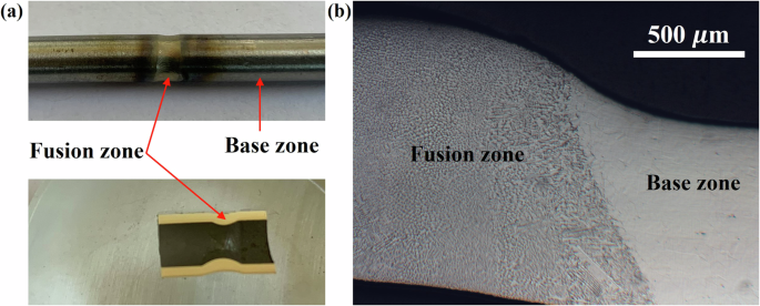
a Images of the weld joints. b Metallurgical morphology of the weld joint and base metal by optical microscopy.

a The 316L stainless steel base metal section. b 316L stainless steel weld joint section.
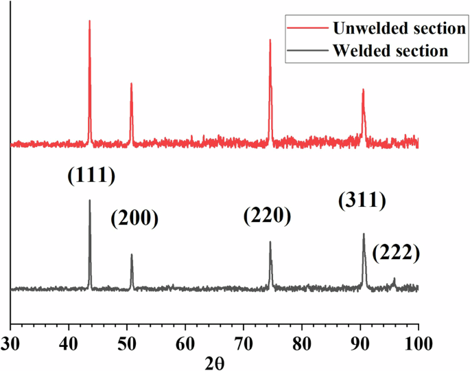
XRD patterns of 316L stainless steel weld joint and base metal.
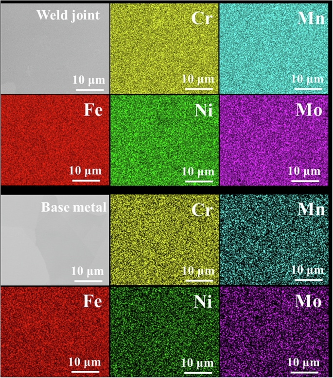
SEM/EDS images of the weld joint and base metal of 316L stainless steel.
A tube section includes the weld joint part and the base metal part was cut from the hot leg of the loop after the 260-h molten salt circulation test for post-corrosion material characterizations. The cut tube section was ultrasonically cleaned and a series of material characterization analyses were performed to characterize the corrosion performance. To evaluate the corrosion of the cross-section of the tube section after corrosion testing, the tube sample was cut axially, mounted with epoxy, ground, and polished. Figure 5 shows the SEM image of the post-corroded tube cross-section at the base metal part and weld joint part, respectively. From Fig. 5a, a local corrosion attack was observed at the subsurface of the base metal part. This local corrosion attack evolves by forming dense voids as displayed in Fig. 5b. The heterogenous corrosion attack and the discontinuous void morphology are the widely observed phenomena in molten salt corrosion17,21, which is likely because of the heterogeneous dissolution of thermodynamically susceptible elements from alloy. Similar to the corrosion at the base metal part, the corrosion attack at the weld joint occurs locally in the form of voids as well. However, the corrosion-resolved voids do not gather densely but spread discretely as a dendritic structure (Fig. 5c, d). Compared with the corrosion at the base metal part, the voids at the weld joint penetrate deeper in the alloy although the sparse dendrite corrosion attack may result in less amount of alloy elements dissolving into molten salt. Based on the post-corrosion material characterization, both the 316L stainless steel base metal and the weld joint in the molten salt circulation loop are corroded as forming voids in the subsurface of the alloy, not via intergranular attack (EBSD images of the post-corroded samples in Supplementary Fig. 1). This is unexpected since the intergranular corrosion attack has been widely identified as the dominant corrosion mechanism in many molten chloride salt static corrosion studies22,23. Even the corrosion of the same alloy (316 stainless steel) performed in the same salt (NaCl–MgCl2 eutectic melt) as this study at static condition has recognized the corrosion mechanism as the intergranular attack24. This unusual phenomenon could be ascribed to the flow condition induced by the circulation loop or the different impurity levels in the salt melt.
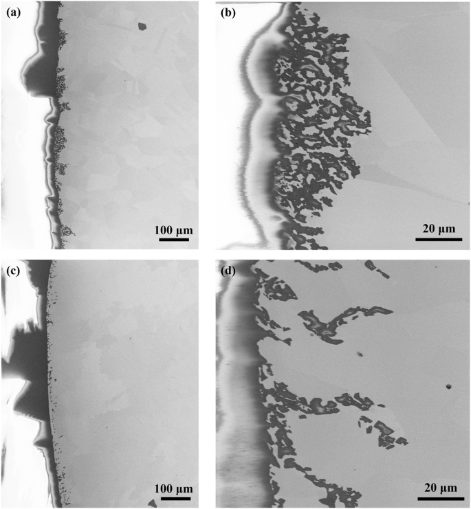
a The base metal part at lower magnification. b The base metal part at higher magnification. c Weld joint part at lower magnification. d Weld joint part at higher magnification.
To further understand the mechanism of the dendrite corrosion attack of 316L stainless steel weld joint in NaCl–MgCl2 molten salt circulation loop, EDS mappings on the post-corroded tube cross-section at the weld joint and base metal parts were performed and compared. The EDS mapping results shown in Fig. 6 indicate the significant depletions of Fe, Cr, and Mn at both the base metal and weld joint parts. This is expected since Fe, Cr, and Mn are the most thermodynamically susceptible elements in 316L stainless steel3,17. In Fig. 6a, the depletion of Fe, Cr, and Mn from the base metal artificially enriches Ni and Mo within the corrosion microstructure as observed in the previous literature17,18. The EDS mapping for the weld joint part as displayed in Fig. 6b shows that all the main constituent elements dissolve into salt in the zone of voids, even including Ni and Mo. This indicates that the open voids are formed in the weld joint during the molten salt corrosion. The different corrosion performances of the base metal part and the weld joint part might have resulted from their different microstructures as identified by the pre-material characterizations above. The different microstructures could change the diffusion rates and even the migrating pathways for corrosion-susceptible elements such as Fe, Cr, and Mn in 316L stainless steel. This further hinders their timely refills at the corrosion attack area (e.g. voids) at the weld joint and the corrosion attack results in the dissolutions of Ni and Co. However, the detailed explanation for the dendrite corrosion attack at the weld joint section of 316L stainless steel is still unclear and more work is still necessarily needed to be performed to unveil it.
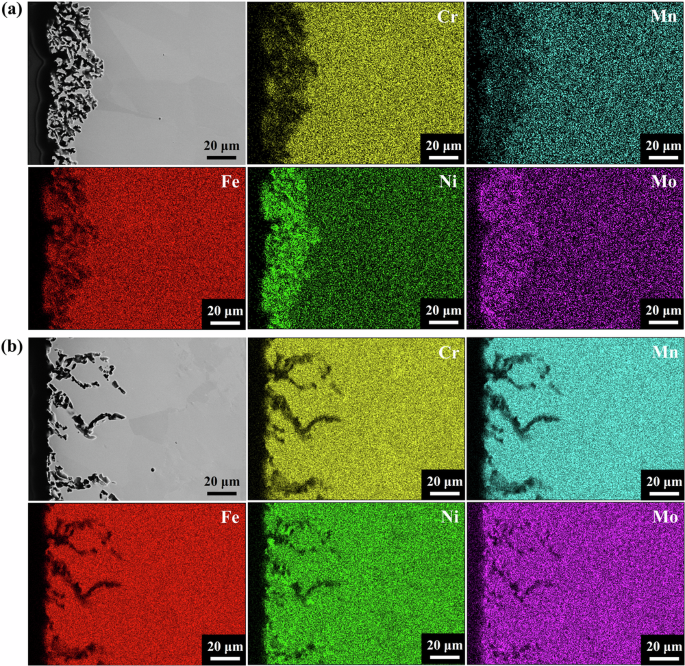
a Base metal part. b Weld joint part.
In this study, the corrosion performance of the 316L stainless steel weld joint in NaCl–MgCl2 eutectic molten salt circulation loop was studied and compared with 316L stainless steel base metal in the same environment. Unlike the intergranular corrosion attack occurring in static NaCl–MgCl2 eutectic molten salt24, the corrosion of 316L stainless steel in molten salt circulation loop behaved as forming voids in the subsurface which is commonly observed in molten salt dealloying25,26. The morphologies of the corrosion resulted in voids in 316L stainless steel weld joint and base metal are demonstrated not to be the same as well. The local corrosion attack in the form of voids in the weld joint part was found to evolve discretely as a dendritic structure while the voids in the base metal part are more likely to appear densely. Compared with the corrosion at the base metal part, the voids at the weld joint penetrate deeper in the alloy and might present a greater threat for component failure although this corrosion results in less amount of alloy elements dissolving into molten salt. In addition, the voids in the weld joint part are open, being formed by the dissolutions of all the constituent elements of the alloy. The different corrosion performances of the 316L stainless steel weld joint and base metal parts could have resulted from the alteration of the alloy’s microstructure in the orbital welding process. The present study can provide guidance and evaluation on alloy welding for the deployment of MSR.
Methods
The molten salt loop in this study is built with 316L stainless steel whose composition is shown in Table 1. The loop itself adopts the design from TerraPower LLC18 and the schematic is shown in Fig. 7. The dimension of the whole loop frame is 32” × 32” × 32” while the loop body is a 9” × 12” parallelogram. The diameter of the tube to construct the loop is 0.25” with a wall thickness of 0.035”. Three tanks are equipped with a loop as shown in Fig. 7. The two tanks at the bottom are flush salt tank and primary salt tank, which are utilized to store the salt for loop cleaning and actual corrosion test, respectively. The tank at the top of the loop is the surge tank designed for safety to allow for excess molten salt volume to expand, if necessary, without pressure build-up. The heat up of different sections of the loop was achieved by the wrapped nichrome heating wire on the loop main body. The natural circulation of the loop was initiated by setting a temperature gradient along the loop using a nichrome heating wire. The monitoring of the temperature for the loop was achieved by the thermocouples welded at different sections of the loop. The temperatures of the hottest section and coldest section of the loop were maintained at around 620 °C and 500 °C during the loop circulation, respectively. The salt flow rate of the natural circulation loop was determined to be about 6.3 cm/s as reported in our previous study17. More detailed information regarding the setup of the loop can be found in the literatures17,18. The NaCl–MgCl2 molten salt flowing through the loop was prepared with 58.5 mol% anhydrous NaCl salt and 41.5 mol% anhydrous MgCl2 salt based on their eutectic mixture ratio. The impurities of the salt mixture were identified by Inductively coupled plasma mass spectrometry (ICP-MS) analysis in which the most prominent impurity elements and their corresponding concentrations were 0.79 ppmw (part per million by weight) Li, 5.44 ppmw S, 15.7 ppmw K, 6.99 ppmw Ca, 0.03 ppmw Cr, 0.01 ppmw Mn, 0.13 ppmw Fe, and 0.23 ppmw Ni. The oxygen level in the salt is around 300–400 ppmw. To study the welding effect on material corrosion in the molten salt loop, a tube section the length of around 15 cm was cut from the hot section of the loop and then welded back using the orbital welding technique as displayed in Fig. 1. The loop naturally circulated for about 260 h until it succumbed to corrosion product buildup and clogging, which is also the corrosion testing time in this study.
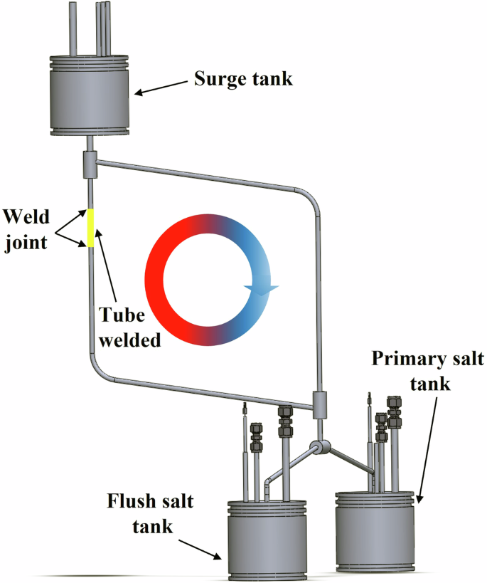
The schematic of 316L stainless steel natural circulation loop.
SEM coupled with EDS and EBSD were performed to characterize the samples before and after the corrosion experiment. The samples for SEM/EDS analyses were ground with SiC abrasive papers of different grit sizes up to 1200 grit and then polished on the polishing pads by 3 μm, 1 μm diamond suspensions, and 0.04 μm colloidal silica suspension. The samples for EBSD analyses were ultraly polished by a vibratory polisher. All SEM/EDS analyses were performed on a Zeiss Gemini 300 device equipped with an energy-dispersive X-ray spectrometer and Pathfinder software. The EBSD data was acquired on a Helios Plasma-Focused Ion Beam (PFIB) G4 system, equipped with a high-speed EBSD detector at a voltage of 30 kV and a current of 51 nA. XRD analysis was performed at Bruker D8 Discover diffractometer using a Cu-Kα micro X-ray source.
Responses