Effect of titanium and vanadium nano-carbide size on hydrogen embrittlement of ferritic steels
Introduction
In the search for safer and more lightweight vehicles, the automotive industry has been engaged in the development of Advanced High Strength Steels (AHSS)1,2,3. The goal for these steels is to obtain both high strength and high ductility to provide good formability and toughness. Many strengthening mechanisms in steels can, however, also cause Hydrogen Embrittlement (HE). Microstructural features like hard phases, retained austenite and refined grains attract hydrogen that can cause fracture4,5,6,7,8,9. HE shows as a reduction in ductility or strength in steels, which leads to premature failure of components. A frequently researched mitigation method for HE is to trap hydrogen in the microstructure where it cannot lead to fracture10,11,12,13. Crucial in this method is to decrease the amount of diffusible hydrogen in the microstructure, which can diffuse towards critical areas and as such is considered the main cause of HE13,14,15,16,17,18,19. Carbide precipitates are one solution that is looked into in this regard, since they are expressly useful for precipitation strengthening of steel, while at the same time providing a wide range of hydrogen trapping capabilities11,14,16,17,20,21,22,23,24.
The specific trapping strength of precipitates depends on where the hydrogen is trapped, which can be either in the elastic strain field around the precipitate, on the precipitate/matrix interface or in the precipitate bulk25. The strength with which hydrogen is trapped is determined by the activation energy EA that is required for hydrogen to desorb from the trap. Experimental, as well as numerical studies have attempted to identify these energies. The strain field around precipitates is generally considered the weakest trap with values ranging between 2 to roughly 30 kJ/mol23,26,27. The precipitate/matrix interface can host a number of trapping sites, including interstitial locations, vacancies and misfit dislocations. The activation energies for these types of traps have been found to range from approximately 20 to 30 kJ/mol for interstitial sites13,24,28, to 60 up to 90 kJ/mol for carbon vacancies on the interface10,27,29,30,31. Misfit dislocations fall in a large range in between the two23,29,32. Lastly, carbon vacancies in precipitate bulk are found to be the strongest traps with energies of around 100 to as much as 145 kJ/mol10,17,21,23,26,27,33,34,35. Which types of traps are present depends on the type of precipitate as well as their size and morphology. Small coherent precipitates have a large elastic strain field but lack misfit dislocations. Upon precipitate growth, the misfit with the steel lattice becomes too large and misfit dislocations start forming. This happens around a size of 4.2 nm for TiC precipitates, but only around 20 nm for VC precipitates31,36. Even larger precipitates become fully incoherent with the matrix, at which point there is a large concentration of carbon vacancies, but the interface starts forming a diffusion barrier for hydrogen diffusion into precipitate bulk11,23,36.
The synergistic effect of precipitate size on strength of a steel, as well as hydrogen trapping behaviour thus becomes an important field of study. Our previous work focused on comparing two types of precipitates, namely TiC and VC, of two different size distributions after hydrogen charging in a gaseous atmosphere10. Here, as well as in other studies, it was found that large incoherent precipitates store a significant amount of hydrogen at a high activation energy in bulk C-vacancies, that do not cause any HE10,11,21. However, since small nano-sized carbides were not affected during gaseous charging, weaker reversible traps could not be studied. A different charging environment is therefore required to study the effect of nano-sized carbides, which are more beneficial for precipitate strengthening and hydrogen storage on interface traps13,31,37. The hydrogen trapping characteristics of TiC and VC precipitates has been studied in detail experimentally by, for example, Wei and Tsuzaki23,38, Depover and Verbeken13,16,17 and numerically by Di Stefano29 and Sagar27. It remains important, however, to consider the implications of precipitate size on the mechanical properties of steels and couple their hydrogen trapping capabilites to fracture mechanisms. This work characterises the effects of VC and TiC nano-precipitates of different sizes after in-situ tensile testing in an electrochemical hydrogen charging environment, and relates the trapping of hydrogen around nano-carbides to the mechanical behaviour and fracture mechanisms. A fracture micro-mechanism is presented that explains the detrimental effect of intergranular nano-carbides compared to those present in the grain interior. This information is integrated in order to find a preferred precipitate type and size distribution for the design of steels for use in a hydrogen environment.
Methods
Heat treatment and characterisation
Two different ferritic steel compositions were used in this study, both of which were supplied in a hot-rolled condition by Tata Steel in IJmuiden. The alloy compositions are give in Table 1. Both alloys are fully ferritic but were alloyed with titanium and vanadium, respectively, in order to maximise precipitation of TiC and VC nano-precipitates. Each steel was subjected to a short (SN) and long (LN) heat treatment in nitrogen atmosphere, to realise two different precipitate size distributions. The heat treatments consisted of a heating rate of 5 °C/min to temperatures of 700 °C for the TiC alloy and 650 °C for the VC, followed by isotherms of 2 hours for the SN and 20 hours for the LN treatment. The temperatures were chosen in order to keep the steels below the Ac1 temperature for austenite formation10. Cooling down was performed at approximately 1 °C/min, which was limited by the furnace.
The as-received steels were machined into either 2 mm x 20 mm x 110 mm sheets for microstructural characterisation and Thermal Desorption Spectroscopy (TDS), or dog-bone specimens to use in tensile testing. All sheets and dog-bone specimens were sanded to a P1000 grit finish to ensure a repeatable surface finish before the heat treatments. Specimens for microstructural characterisation were cut from the sheets and further polished up to a 0.04 μm colloidal silica finish to allow for Scanning Electron Microscopy (SEM), Electron Dispersive X-ray Spectroscopy (EDS) and Electron Backscatter Diffraction (EBSD) analysis. EBSD and EDS were performed on a Thermo Fisher Scientific™ Helios™ G4 PFIB UXe SEM capable of performing simultaneous EBSD and EDS measurements. The acceleration voltage used was 20 kV, with a 3.2 nA probe current and a step size of 50 to 70 nm. EDS analysis of the fracture surfaces was performed at an acceleration voltage of 10 kV and a probe current of 1.6 nA. Transmission Electron Microscopy (TEM) analysis was performed to characterise precipitate sizes. This was done using a Thermo Fisher Scientific™ Cs corrected cubed Titan™ machine after polishing samples to 30 μm thickness and Ar+ ion milling to electron transparency.
Resulting microstructures
Table 2 gives an overview of the microstructural characteristics of the steels after heat treatment. All four microstructures were fully ferritic. Grain areas were obtained from EBSD, and precipitate sizes were obtained from TEM images where the size reported is the average size ((sqrt{length* width})) of manually measured precipitates. Since distributions of both the grain areas and precipitate sizes were very wide, they are reported in the way described in ASTM E1181 for randomly distributed grain sizes of large range39. A more in-depth description of microstructural characterisation is given in our previous work10. The grain area in the TiC steel increases from an average of 3.8 μm2 in the TiCSN to 5.0 μm2 in the TiCLN condition. This is only a slight increase, which is attributed to grain boundary pinning by the nano-sized TiC precipitates found in TiCSN. SEM microstructural overviews of both TiCSN and TiCLN are given in Fig. 1a, c, respectively. It can be observed that the TiCLN condition indeed contains a large amount of intergranular precipitates that have grown as a result of the long heat treatment and caused boundary pinning. The precipitates increase from 8.6 nm to 30.3 nm on average. At a size of approximately 4.2 nm, TiC nano-precipitates lose coherency with the matrix and misfit dislocations on the matrix-precipitate interface are created36. Essentially all precipitates in TiCSN and TiCLN are therefore considered semi-coherent with the matrix. The average spacing between precipitates does not grow significantly after the heat treatments. Larger >100 nm precipitates that are fully incoherent with the matrix exist in the TiC steel from the as-received condition, which do not change in size during the heat treatments. These slightly skew the averages to higher numbers, which means that the majority of precipitates, even in TiCLN, will be smaller than 30 nm. The average spacing for these large precipitates is 3 μm on average, which is 3 orders of magnitude higher than that of the small precipitates. The value is listed separately in Table 2 and does not change with heat treatment duration. Representative images of precipitates found in all four steels are shown in Fig. 2. Since the grain size does not change with the longer heat treatment, the precipitate growth is responsible for the drop in hardness from 272 to 238 HV2 after the long treatment.
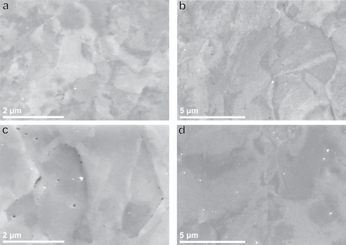
a TiCSN, b VCSN, c TiCLN and d VCLN heat treatment conditions. Precipitates are visible in black.
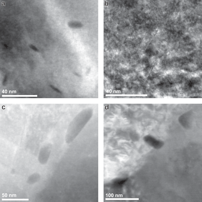
High Angle Annular Dark Field (HAADF) TEM images of precipitates in a) TiCSN, b) VCSN, c) TiCLN and d) VCLN heat treatment conditions.
The VC steel has larger grains than its TiC counterpart, which do grow during the heat treatments, in contrast to those in the TiC steel. An average of 12.5 μm2 in VCSN grows to 24.9 μm2 in VCLN. The precipitates also increase in size from 9.9 nm to 17.6 nm on average. Vanadium carbides were observed in literature to be mostly coherent with the matrix up to a size of 20 nm31, therefore most precipitates in VCSN are considered coherent, as well as most precipitates in VCLN. Precipitate spacing grows from an average of 24 nm to 49 nm. Large incoherent precipitates are much more scarce in the VC than in the TiC steel, so this number is a more accurate description of the average size of VC nano-precipitates present in the steels. Both grain and precipitate growth contribute to a drop in hardness from 241 to 230 HV2. SEM microstructural overviews of both VCSN and VCLN are given in Fig. 1b, d, respectively. Table 2 includes a concise description of the precipitate distribution in all steels. Additionally, EBSD representations of the microstructures, as well as precipitate size distributions have been shown in Supplementary Figures 1 and 2.
In-situ slow strain rate tensile testing
In order to assess the amount of embrittlement in each steel, they were subjected to in-situ Slow Strain Rate Tensile (SSRT) tests in an electrochemical hydrogen charging environment. The setup that was designed for the test is shown in Fig. 3a and the geometry of the tensile specimens is given in Fig. 3b. The specimens were sanded with a P1200 grit paper before being submerged in a solution of 3.5% NaCl, as well as 3 g/L ammonium thiocyanate (NH4SCN) to act as a recombination poison. Each specimen was charged with hydrogen at a current density of 1 mA/cm2 for 2 hours prior to starting the test, with continued charging during the full duration of the test. Because of the design of the tensile grips, only the gauge length of the specimen was subjected to the current. The SSRT test was conducted at a crosshead displacement speed of 14.4 mm/h which corresponds to a maximum strain rate of 1 ⋅ 10−4 s−1 in the specimen gauge length. The tests were performed on a Zwick Z100 universal tensile tester with the strain being recorded using an Epsilon 4030 submersible extensometer. The bath and connectors were designed specifically for this research. The current was applied using a Bio-Logic VSP-300 potentiostat. Specimens were removed from the bath immediately after fracture, cleaned with demiwater, dried with compressed air and stored in a freezer at −86 °C until removed for TDS analysis. The strain at fracture of each specimen (({epsilon }_{f}^{{H}_{2}})) was compared against that of nonhydrogen charged specimens (({epsilon }_{f}^{Air})) found in our previous research10 and used to calculate the hydrogen embrittlement index HEI. The formula with which the HEI was calculated is listed in Equation (1).
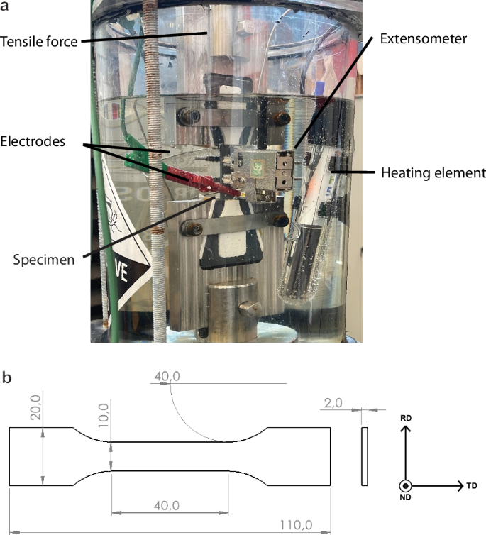
a Overview of the in-situ setup used for tensile testing and b the dimensions (in mm) of the tensile specimen geometry used in this study.
Hydrogen analysis
In addition to post-mortem H analysis after the SSRT tests, each steel was also charged with hydrogen outside of the tensile testing environment to investigate the amount of hydrogen absorbed without any application of stress or strain. Sheet specimens subjected to the heat treatments were sanded with a P1200 grit paper to ensure a surface finish identical to that of the SSRT specimens before being charged in 3.5% NaCl + 3 g/L NH4SCN solution for 2 hours. Specimens were moved to the TDS analysis immediately after charging. Both the sheet specimens and the full SSRT specimens were subjected to TDS analysis in a Bruker G8 Galileo ONH analyser equipped with the IR07 infrared furnace for accurate temperature ramping. TiC specimens were measured up to 900 °C, the full range of the furnace, while VC specimens were ramped up to 700 °C because no H was desorbed above these temperatures for this steel. Heating rates of 1, 0.66 and 0.33 K/s were used in order to obtain peak shifting behaviour of the hydrogen desorption peaks. Fitting of peak temperatures obtained at different heating rates according to the simplified Kissinger equation40, shown in Equation (2), allows for the determination of activation energies for specific peaks that can be linked to microstructural hydrogen traps.
In this equation Tmax, ϕ, R and EA are the peak temperature of a specific H desorption peak in K, the heating rate in K/s, the universal gas constant 8.3415 J/mol−1K−1 and the activation energy for hydrogen desorption of the specific hydrogen trap in kJ/mol, respectively. By fitting (ln (phi /{T}_{max}^{2})) to (1/Tmax), EA can be inferred from the slope.
Results
Hydrogen absorption
An overview of the hydrogen contents of all steels is given in Table 3, including activation energies calculated for desorption peaks of the non-strained samples, which are shown in Fig. 4. Overall, the TiC steels absorb more hydrogen than the VC steels, especially after the long heat treatment. All TiC steels contain a significant amount of hydrogen that is trapped at high temperatures, which was only found in one of the VC specimens. The amount of hydrogen that was released in the first desorption peak (chosen as 50 to 475 °C) was therefore calculated separately to compare the hydrogen trapped at low temperatures only. These values will be used to support further discussion in this article instead of the total hydrogen content. It becomes clear that with an absorbed H content of 2.18 wppm for TiCSN and 1.82 wppm for VCSN, the TiC steel absorbs more hydrogen at lower temperatures than the VC steel, and not all of the extra hydrogen absorbed by the TiC steels is that which is trapped at a high temperature. In both the TiC and VC steels, the SN steel absorbs significantly more H than the LN steel, which is likely a result of precipitate growth as well as grain growth which causes a reduction in grain boundaries available for trapping hydrogen. Activation energies obtained for the low-temperature desorption peaks show good correspondence between SN and LN heat treatments. TiCSN and VCSN have similar energies of 14 and 19 kJ/mol while TiCLN and VCLN have energies of 37 and 27 kJ/mol, respectively. This suggests similar trap types between the two precipitate types, that change with heat treatment duration. The hydrogen trapped in the high-temperature peaks above 500 °C was previously shown to be stored in large incoherent precipitates10 and can be seen to be slightly reduced after the long heat treatment. It can be calculated from Table 3 to be 0.39 and 0.27 wppm for TiCSN and TiCLN, respectively, while it is only 0.19 for VC SN and less than 0.01 wppm for VCLN. Activation energies for the high-temperature traps could only be determined for TiCSN since the amount of hydrogen trapped in the other steels was insufficient to identify peak at all heating rates. The energies obtained were 69 and 115 kJ/mol for two distinguished peaks that can be observed in Fig. 5.
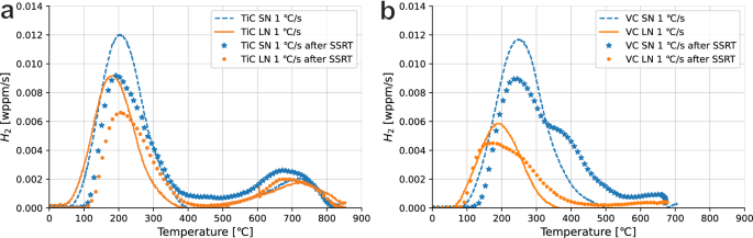
a TiC and b VC unstrained samples against the post-mortem sample including deformation.
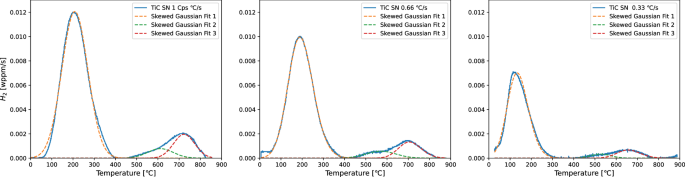
Peaks for TiCSN for all heating rates.
Mechanical behaviour
In order to compare the mechanical behaviour of the specimens studied in this research, Fig. 6 compares their SSRT curves to those obtained for their uncharged counterparts studied in our previous work10. A more detailed overview of mechanical performance is given in Table 4. The specimens tested in-situ perform very similarly to the uncharged ones for the largest part of the tensile curve. No significant deviations in yield behaviour nor UTS are found except for experimental uncertainties. A notable exception is TiCLN, which has an early onset of necking that causes a lower UTS and higher HEI. In both cases for the VC steels, the longer heat treatment results only in a reduction in strength instead of an increase in ductility. This is true for both heat treatment durations. The largest effect of the in-situ hydrogen charging is observed as a reduction in strain at fracture ϵf. Both TiCSN and VCSN show an HEI value of around 15%. VCLN reduces in ductility by 19%. TiCLN, however, is evidently more embrittled with an HEI value of 37%. This condition shows both a larger ductility without hydrogen, as well as the lowest ductility with hydrogen.
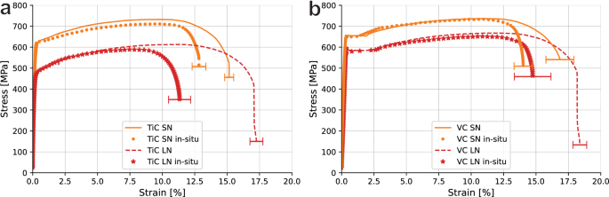
a TiC and b VC specimens tested in-situ during electrochemical hydrogen charging in comparison with uncharged specimens. Errors are standard deviations in fracture strain. Uncharged data was obtained by Boot et al.10.
Discussion
Characterising the specific microstructural features responsible for trapping hydrogen is often complicated by overlap of diffferent desorption peaks41. Other than hydrogen traps in precipitate features, dislocations and grain boundaries often show desorption peaks at near identical temperatures11,17. In this view, the TiC steel provides a good study case since the grain structure is not significantly changed between the SN and LN heat treatments. The reduction from 2.18 to 1.26 wppm of absorbed hydrogen at low temperatures can therefore confidently be ascribed to a difference in trapping in or around the precipitates. The obtained activation energy of 14 ± 4 kJ/mol for TiCSN is close to values obtained by DFT studies. Sagar et al.27 found values of 11.5 kJ/mol (−0.12 eV) and 10.5 kJ/mol (−0.11 eV) for the activation energy of the tetrahedral interstices on the coherent precipitate/matrix interface and in the first iron layer, respectively. These fall within the range of 18 ± 12 kJ/mol found for the more general coherency strain field of TiC by Di Stefano et al.29. The desorption peak of TiCLN was measured as 37 ± 3 kJ/mol, which matches with several reported values from both DFT and experimental studies on the activation energy of hydrogen trapped within misfit dislocations on the semi-coherent interface. Di Stefano et al. calculate this value as 47 kJ/mol (−0.49 eV)29 and Hammer et al.32 calculate it as approximately 43 kJ/mol (−0.45 eV). An experimental value of 43 kJ/mol was also obtained in our previous work where identical steels were charged in a high-temperature H2 environment10.
Activation energies obtained for the VC steel were remarkably similar to that for the TiC steel. The VCSN condition traps hydrogen with an activation energy of 19 ± 5 kJ/mol. Though modelling results on VC are more scarce, values of between 12 and 17 kJ/mol (−0.13 & −0.18 eV) were obtained by several authors for trapping sites in the iron lattice near the matrix/precipitate interface29,32,42. Hammer et al. furthermore obtained a value of approximately 29 ± 6 kJ/mol (−0.30 eV) for the activation energy of hydrogen trapped in a misfit dislocation core on the semi-coherent interface. This matches well with a value of 27 ± 8 kJ/mol measured for the VCLN condition in this research. The fact that values between SN and LN conditions in both steels are similar indicates that the trapping behaviour between the TiC and VC nano-carbides is similar as well. The hydrogen is stored in the first iron layers around the interface of small (semi-)coherent carbides after the SN treatment, but in misfit dislocation cores on the interface of semi-coherent carbides after the longer LN treatment when precipitates have grown. These are all interface traps. Since less interface is available as the nano-carbides increase in size this explains the reduction in absorbed hydrogen after the longer heat treatment for for TiC steel and partly for the VC steel. The reduction from 1.82 to 0.79 wppm in VCLN is not only a result of reduced VC interface trapping, but also of a reduced grain boundary density in VCLN resulting from grain growth. Grain boundaries have been shown to appear at similar desorption temperatures to what was measured in this research11, so they can be expected to play a role even though their behaviour was masked by the desorption peak of the carbides.
Both TiCSN and TiCLN are shown in Fig. 4 to trap H at higher temperatures as well. Figure 4a shows the deconvoluted high-temperature peaks for TiCSN, which were calculated to have activation energies of 69 and 115 kJ/mol, respectively. Our previous research identifies the hydrogen that desorbs at high temperatures to be trapped inside the bulk of large incoherent carbides10, although no activation energies for these traps were obtained in that work. Electrochemical hydrogen charging at room temperature cannot overcome the diffusion barrier of the incoherent precipitate/matrix interface, which means that these traps are not affected by the charging in this work. The hydrogen is already present in the as-received material. The value of 115 ± 16 kJ/mol that is found here for the high-temperature peaks corresponds well with numerically obtained values of 105 to 113 kJ/mol for H trapped in C-vacancies inside the precipitate bulk27,35. The same trap has been studied experimentally, where energies of 80 to 90 kJ/mol were found21,23. Incoherent TiC precipitates in general were found to have a wider range of trapping energies anywhere between 53 and 145 kJ/mol through different analytical means that could explain their difference11,43,44. Wei and Tsuzaki observe trapping energies for H trapped in incoherent TiC to range from 68 to 137 kJ/mol depending on austenization temperature and consequently precipitate size23. However, a difference in precipitate size does not indicate a difference in trap type, so varying activation energies are not expected. There is still uncertainty towards the nature of differently obtained activation energies for the seemingly identical trap site of the C-vacancy. The influence of connected vacancy networks is sometimes discussed in literature as an explanation for lower activation energies21,29, but a conclusive answer is not yet found.
Figure 4b shows peak broadening for the VC spectra obtained post-mortem after the SSRT test, and even the appearance of an extra shoulder in the desorption curve for VCSN. Although the appearance of an extra peak suggests the creation of a new hydrogen trap, the activation energies for the first and second peaks were found as 17 and 21 kJ/mol. The full deconvoluted peaks can be found in the Supplementary Fig. 3. These energies are so similar that it is difficult to assign separate microstructural features to both individually. It is more likely that this is an effect of a high degree of plastic deformation, which was observed in DP1000 steel by Drexler et al. as peak broadening with increasing plastic strain45. A high degree of plastic deformation retards hydrogen diffusion from the bulk which delays the appearance of the desorption peak to higher temperatures. Since the coherent VC precipitates present in VCSN and to a smaller degree in VCLN were of a smaller size as well as more elongated than those seen in the TiC steels, they play a larger role in dislocation accumulation and precipitate strengthening. This is the main cause of the similar strength of the VC steels to that of the TiC steels, although the grain size is much larger in the VC steels. Increased dislocation accumulation around VC precipitates could therefore lead to a retardation in the desorption peak after straining to a larger degree that is not observed in the TiC steels. Since the average precipitate spacing in VCSN is lower than in all other steels at 24 nm, these precipitates provide a larger barrier for dislocation movement. This causes a larger dislocation accumulation around the precipitates, such as observed by Gong et al.46, which causes the most retardation of H desorption that shows in the TDS curve as a second peak. However, because the trap is still the precipitate itself, the activation energy does not change.
Both the TiC and VC steels are ductile steels without a large amount of strain hardening. Judging from Fig. 6 and Table 4, the only observed effect is that of a reduction in fracture strain as indicated by the HEI. Both VC steels, as well as TiCSN embrittle by 15 to 20%. TiCLN instead embrittles by 37%, almost twice as much as all other steels. In order to investigate the reason, more metrics should be studied. Table 5 lists the UTS, onset points of necking and embrittlement indexes calculated for both metrics (HEIUTS and HEINeck, respectively) in the same way as listed in Equation (1). The benchmark values on uncharged specimens used for the embrittlement indexes were obtained in our previous research10. One important observation from this table is that the HEINeck is negligible for both VC steels, and insignificantly changed for TiCSN. There is no evidence of an early onset of necking in these steels, meaning that the absorbed hydrogen does not impact the ductility of these steels up until the point of necking. All reduction in ductility that constitutes the hydrogen embrittlement takes place after the point of UTS e.g. as accelerated necking. In contrast, the onset of necking is reduced by 30.6% in TiCLN after in-situ testing compared to the benchmark, which is of the same order as the 37% total embrittlement of this steel. As a consequence of this early onset of necking, the UTS of TiCLN is reduced by 11.6% compared to the benchmark. The other three steels do not show any significant reduction of UTS outside of any variability that is expected between different sets. What this behaviour indicates is that the eventual localisation of plastic deformation is the governing factor in embrittlement for these steels. In order to elucidate exactly why TiCLN behaves so differently, the fracture mechanisms need to be studied.
Figure 7a, b, which show frontal view of the post-mortem SSRT specimens, display significant side-cracking in TiCLN compared to that in VCLN. This indicates a reduced resistance to crack initiation and growth in the TiC steel, which serves as a cause for increased HE. Figure 8a and b show SEM fractographic images of the fracture surfaces of the same samples. The highlighted area corresponds to areas of brittle fracture around the edges of the tensile specimens that were in contact with the electrolyte, as is often seen in in-situ tests47,48,49. A higher magnification image of the brittle zone in TiCLN is given in Fig. 8c, where it can be observed that fracture is exclusively intergranular (IG) in this region. Extensive secondary cracking can be seen and all facets are of a size corresponding to the grain size. Although behaviour in VCLN is very similar, as can be seen in Fig. 8d, this fracture surface still exhibits some transgranular (TG) fracture that contains ridges characteristic of the quasi-cleavage (QC) fracture surface50. These facets are larger than any of the ones observed in TiCLN which corresponds to the larger grain size found in the VC steel. In the hydrogen embrittlement model as proposed by Wasim et al.51, embrittled fracture surfaces exhibit more IG fracture with increasing hydrogen content. This matches the higher hydrogen content of TiCLN (1.26 wppm) compared to VCLN (0.79 wppm). However, the hydrogen content is clearly not the only factor governing the emergence of intergranular fracture, since TiCSN has an even higher H content but a much lower HEI.
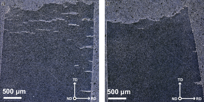
a TiCLN and b VCLN. The top surface in this figure is the fracture surface of the tensile specimens, crack that can be observed are secondary cracks on the side surfaces of the specimens.
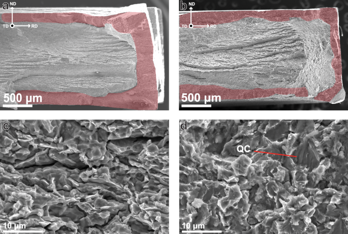
a, c TiCLN and b, d VCLN. Highlighted areas in a and b correspond to brittle fracture surface.
Higher magnification SEM fractography was performed in order to investigate the nature of increased IG fracture in TiCLN compared to the other steels. Figure 9a shows an image of precipitates on a cracked grain boundary from the TiCLN steel, of which an EDS line scan is shown in Fig. 9b. The precipitates on the grain boundary are identified as TiC, which shows that the intergranular fracture surface is in fact localised to boundaries that contain precipitates. A reference image of an intergranular surface of TiCSN is shown in Fig. 9c which does not contain any visible intergranular carbides. The fact that TiCLN contains a high degree of intergranular precipitates that are present on the fracture surface can explain the increased tendency for TiCLN to show IG fracture as compared to the other steels. However, TiCLN is not the only surface on which larger IG precipitates were observed. Figure 9d shows an occurence of IG precipitation on the surface of VCLN, although these precipitates could not be identified as VC definitively. This means that the localisation of fracture to the precipitate boundaries is not specific to TiC, but the fact that TiCLN contains many more causes its higher embrittlement.
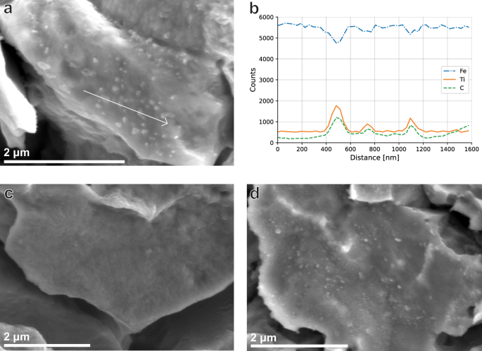
a High magnification of TiC precipitates on a grain boundary on the TiCLN fracture surface. b EDS linescan of the line segment shown in a. c Facet not showing any sign of precipitates on a TiCSN IG fracture surface. d Intergranular precipitates on the VCLN fracture surface.
Furthermore the role of the larger > 100 nm incoherent precipitates should be discussed. Combined EBSD and EDS analysis was performed to investigate the presence of these precipitates around secondary cracks, the results of which are shown in Fig. 10. EDS in Fig. 10b furthermore shows the presence of homogeneously distributed TiC precipitates of sizes > 100 nm. Although these precipitates are not localised around the crack formation, they have been observed to occasionally appear on the fracture surface as shown in Fig. 11a. Large incoherent precipitates are therefore explained to not necessarily localise fracture, but to cause increased IG fracture if they are present on grain boundaries.
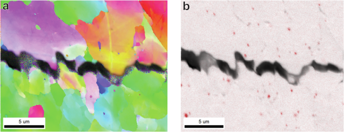
a An Inverse Pole Figure (IPF) of a secondary crack on the side surface of a TiCLN specimen, and b an Electron Dispersive X-ray (EDS) image of the same area in a where Titanium is displayed in red.
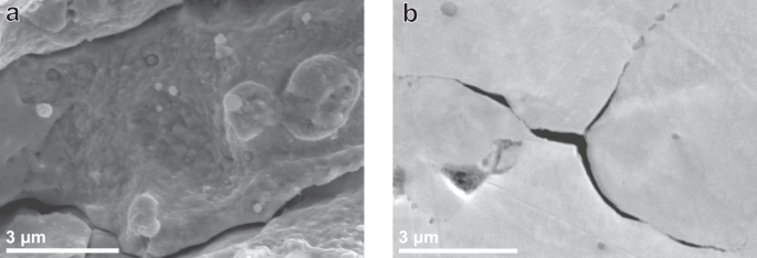
a Observed incoherent TiC precipitates on an intergranular fracture surface. b Nucleated secondary crack on a triple point boundary. Both images were obtained from the TiCLN steel.
The role of intergranular precipitates in hydrogen fracture was investigated previously in literature. Elkot et al. investigated an austenitic high Mn-steel containing κ-carbides and concluded that IG fracture is facilitated on boundaries containing a high concentration of carbides52. They draw parallels to a study by Koyama et al. on a similar steel that also contains IG carbides53. The mechanism proposed by Koyama et al. proposes crack initiation on triple point boundaries, followed by preferential crack growth towards boundaries containing carbides. The carbides act as blockages for dislocation cross-slip along grain boundaries and instead cause dislocation pile-ups that lead to void formation. The void formation eventually causes enhanced IG fracture. Elkot et al. argue that instead of slip bands being the precursor to fracture, they are instead formed upon crack propagation instead of initiation.
Crack initiation on triple-point grain boundaries is something that was observed in this work as well, as indicated in Fig. 11b which shows a secondary nucleated crack on a triple-point boundary in TiCLN. This figure also shows crack propagation along grain boundaries that contain precipitates. The mechanism as discussed by Koyama et al. is therefore likely also active in this steel although it contains different precipitates. The reason that this mechanism is only active for TiCLN is because of the high amount of intergranular precipitates of increased size compared to those in TiCSN. These form as a result of two mechanisms. Firstly, grain boundaries migrate during the heat treatment, but get pinned by existing nano-precipitates that are until then only present in the grain interior. This Zener pinning is also responsible for the negligible growth in grain size between TiCSN and TiCLN. This results in an increased amount of precipitates at grain boundaries. Secondly, the grain boundary precipitates undergo accelerated growth compared to those in the grain interior. It is clearly visible from SEM observations such as those in Fig. 1c that interior precipitates are not visible at similar magnifications that reveal grain boundary precipitates. Precipitates present on the grain boundaries act as barriers to dislocation movement and dislocation pileup around the precipitates occurs. This localised plastic deformation, in combination with the hydrogen present, causes fracture around the precipitate and accelerates IG cracking compared to a steel where the precipitates are present in the grain interior such as TiCSN. This mechanism reveals itself in the tensile curve as an early onset of necking, although the actual plastic deformation is happening on the grain boundaries. Although it has been found that smaller grains can be beneficial to increase HE mitigation54, intergranular presence of carbides with reversibly trapped hydrogen could counter this effect and weaken the grain boundaries instead, causing increased HE. This process is shown in four steps in Fig. 12. Whereas nano-carbides present inside grains are therefore beneficial, carbides present on the grain boundaries could cause increased HE instead. Excessive grain boundary precipitation should therefore be avoided when designing nano-steels for hydrogen service.
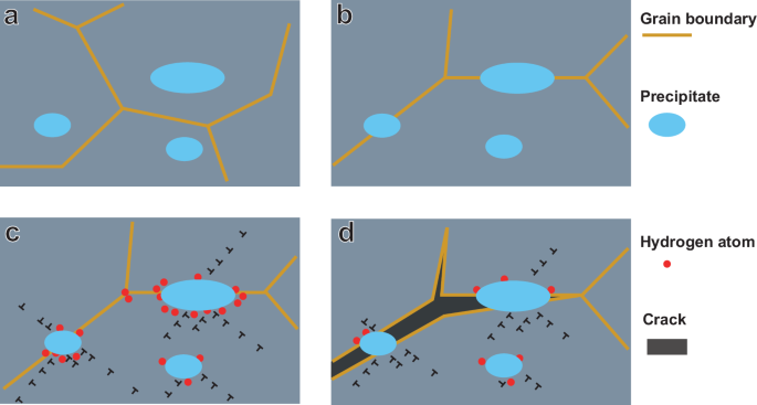
The a starting microstructure, undergoes grain growth after which the b grain boundaries are pinned. c the precipitates accumulate dislocations and trap hydrogen that d weakens the precipitate/grain interface and causes intergranular fracture.
The following conclusions can be drawn from this work:
-
Nano-carbides trap hydrogen in the iron layers near the interface with an activation energy of 14–19 kJ/mol, or inside the misfit dislocation core with an activation energy of 27 kJ/mol or higher. Since this hydrogen is stored on the interface between the precipitate and the matrix, the amount of absorbed hydrogen decreases with increasing precipitate size.
-
Hydrogen charged through electrochemical means is trapped reversibly. Incoherent TiC precipitates of >100 nm in size trap hydrogen irreversibly in C-vacancies with energies of 69 and 115 kJ/mol. The irreversibly trapped hydrogen is present in the material before the heat treatment, and these traps are not influenced by the electrochemical charging.
-
After in-situ Slow Strain Rate Tensile testing, VCSN, TiCSN and VCLN are all embrittled by 15 to 20%, while TiCLN is embrittled by 37%.
-
The reduction in fracture strain is concentrated to the region of necking in the tensile curve for all steels except TiCLN, which has an earlier onset of necking. Plastic strain localisation is therefore the governing factor for HE in these steels.
-
The increased embrittlement in TiCLN is shown to be a result of TiC nano-precipitates present on grain boundaries. These cause dislocation pileup, trap hydrogen there and consequently cause intergranular fracture around the precipitates that results in macroscopic brittle behaviour.
-
VCSN retained the highest strength and ductility out of all four steels while absorbing 2.0 wppm of hydrogen. This is therefore the optimal condition for use in both gaseous and liquid hydrogen environments.
Through this research, some key aspects of hydrogen embrittlement were studied. In-situ mechanical testing in an electrochemical hydrogen charging environment allowed for obtaining the optimal precipitate type and size that retains mechanical properties as much as possible during hydrogen loading, namely the VC steel with a high density of coherent nano-carbides. Furthermore, the adverse effect of intergranular precipitates in relation to hydrogen fracture was discussed. A model was proposed to describe the creation of grain boundary precipitates and their effect on the hydrogen embrittlement of steels in contrast to the beneficial effect of nano-precipitation within grains.
Responses