Effects of electropolishing and plasma ion nitriding on UNS S31603 corrosion in ship scrubber water
Introduction
The International Maritime Organization (IMO) has tightened regulations on sulfur oxides emitted from ship’s exhaust gases1. As a response to the strengthened legislation, ship owners must use low-sulfur fuel or install an exhaust gas aftertreatment device (scrubber). Since large merchant ships consume a lot of fuel, relatively inexpensive scrubber installations are finding widespread use rather than using expensive low-sulfur fuel2. Scrubbers that use seawater as washing water generate sulfur oxides and chlorides during the desulfurization process. Because of these products, local corrosion such as pitting and crevice corrosion occurs inside the scrubber2. Accordingly, application of surface treatment technologies is necessary to improve corrosion resistance and pitting resistance.
Early products, which refer to items in their initial state immediately after being produced in a manufacturing facility, were treated with a mechanical polishing finishing process3. Because mechanical polishing processes the metal surface, it causes a deformation layer and residual stress on the surface. In particular, UNS S31603, with low nickel content, can exist as a metastable austenite phase at room temperature4. The austenite phase can be transformed into a martensite phase by temperature change during manufacturing, but the metastable austenite phase can also be transformed into a martensite phase by mechanical polishing finishing treatment or stress strain caused by product manufacturing5,6. Furthermore, this martensite phase changes the magnetic properties of the material and can cause device failure due to local crystallographic changes7. Electropolishing can solve this problem by removing the microstress8. In addition, corrosion resistance is improved by forming a uniform passivation film9. Plasma ion nitriding also improves corrosion resistance with expanded austenite formed by penetrating nitrogen in the FCC structure10. The electropolishing process was considered for application to the scrubber body. This is because it can be applied to large products and is cheaper than surface treatment processes such as PVD and CVD. In the case of plasma ion nitriding, application to small products such as high-pressure spray nozzles, fan blades, and fillers, which are internal components of scrubbers, was considered. This is because these parts are relatively frequently exposed to erosion damage as well as corrosion. When plasma ion nitriding is performed on austenitic stainless steel, solid solution strengthening occurs as nitrogen atoms invade the face-centered cubic lattice of the base material11,12. At this time, nitrogen atoms that penetrate the interstitial space of the crystal lattice distort the lattice and make dislocation movement difficult. As a result, the hardness of the surface layer improves due to increased resistance to dislocation movement, thereby increasing erosion resistance11,12.
Zatkalíková et al. investigated the electrochemical properties of electropolished UNS S31603 in 0.9% NaCl using cyclic potentiodynamic polarization experiments13. Heuer et al. examined the passivation characteristics of UNS S31603 after electropolishing by conducting a cyclic potential polarization experiment in 0.6 M NaCl14. Zhu et al. evaluated the pitting resistance of UNS S31603 subjected to plasma ion nitriding through electrochemical experiments in a 3% NaCl solution15. As such, the electrochemical properties after electropolishing and plasma ion nitriding have mostly been investigated in an NaCl solution. To our knowledge, there is no published literature on marine scrubber washing water after various surface treatments.
Therefore, it is necessary to examine the electrochemical properties of surface-treated stainless steel in an actual solution. In this investigation, electropolishing and plasma ion nitriding were performed on UNS S31603. Then, the electrochemical characteristics were examined by conducting a cyclic potentiodynamic polarization experiment in washing water for the surface-treated stainless steel.
Results and discussion
Surface treatment
Figure 1 presents the potential change over time during electropolishing. The potential over time rose until 70 s and reached 2.76 V. After that, it rapidly decreased until 220 s and maintained a constant value around 2.45 V. Based on the potential variation data over time, the analysis was conducted as follows. This potential change is due to the electropolishing model that forms on the surface and consists of a dense salt layer or an adsorbent acceptor layer (viscous coating layer)16. The mechanism of electropolishing is critically dependent on diffusion phenomena to explain the smoothness of the surface after the process. The diffusion phenomena must be explained through the principles of mass transport of both cations and anions. Accordingly, the electropolishing mechanism was generally presented as follows. The cations of the base material (metal) form a salt film on the surface through an electrochemical reaction with the electrolyte. The salt film acts as a high resistance to mass transfer. And an acceptor layer like water is formed on the surface of the salt film, which controls mass transfer. Specifically, the thickness of the salt film and the adsorption layer is relatively thicker in the valley regions and thinner at the peaks of the metal surface. Consequently, in the regions where the controlling layer of mass transport is thinner, such as at the peaks, the diffusion of metal ions occurs more rapidly compared to the valleys. Therefore, the height difference between the peaks and valleys gradually decreases, resulting in a more planar metal surface. Metal ions dissolved by the electrochemical reaction cannot diffuse far during electropolishing17. Accordingly, a viscous film layer exhibiting a concentration gradient is formed on the surface. Because the metal surface before electropolishing is rough, with a large number of peaks and valleys, the thickness of the viscous film layer is also formed in an irregular manner. Due to the difference in dissolution reaction rate (concentration gradient) by the non-uniform viscous film layer, the surface becomes flat16. Therefore, the initial non-uniform surface is suggested to have rapidly changed the potential up to 220 s due to the concentration gradient difference. Afterwards, the surface gradually became flat and a similar concentration gradient was formed, and it was judged that the potential over time appeared constant.
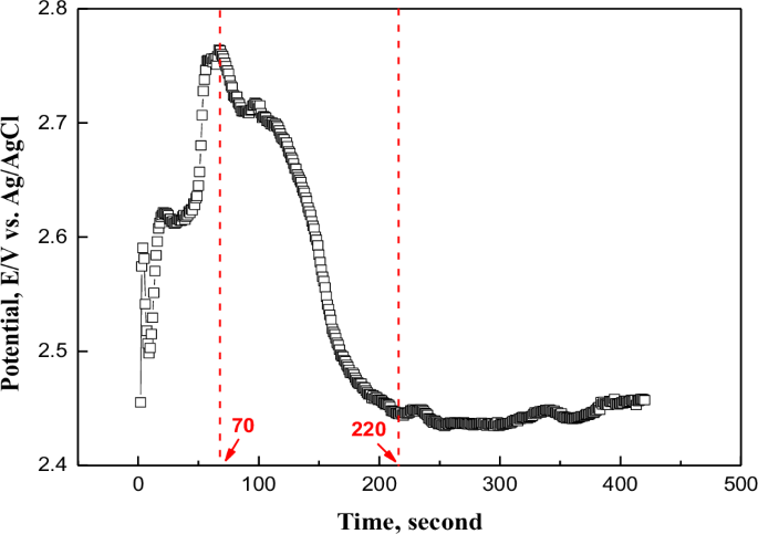
Potential change over time during electropolishing.
Figure 2 displays the surface roughness and 3D profile according to the surface treatment. The surface roughness in this investigation was measured using the commonly employed parameter, the arithmetical mean height (Sa). The surface roughness before and after electropolishing was 0.56 μm and 0.16 μm, respectively. After electropolishing, the surface roughness was reduced by 71.4% based on Eq. (1)18.
In general, when the surface roughness is reduced by more than 50%, it is judged that there is an electropolishing effect; therefore, the electropolishing conditions of this investigation are suitable19. In addition, the height difference between peaks and valleys after electropolishing was significantly reduced compared to mechanical polishing, improving by 94.1%. After plasma ion nitriding, the surface roughness and the height difference between the peaks and valleys increased compared to mechanical polishing. D. Landek et al. reported that after the plasma ion nitriding process on UNS S31603, the surface roughness increases compared to the pre-process state. This increase is attributed to the formation of an expanded austenite layer, Fe4N, and Cr4N on the surface20. The corrosion resistance was improved due to the layer formed by plasma ion nitriding. In this study, the plasma ion nitrided stainless steel exhibited a similar trend to the results of D. Landek et al., suggesting an expected improvement in corrosion resistance20.
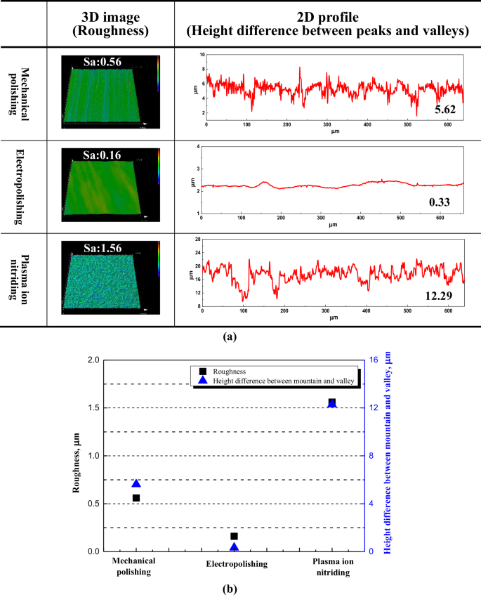
3D image, 2D profile (a) and comparison graph (b) with surface treatment (Unit: μm).
Figure 3 presents the surface of the stainless steel observed after surface treatment using scanning electron microscopy. The surface of the mechanically polished specimen was non-uniform, and a large number of fine burrs and defects were observed. After electropolishing, a uniform and clean surface was confirmed. It is proposed that these surface conditions have a direct effect on gloss. Leonardo et al. reported that process variables (temperature, process time, current density, electrolyte mixture ratio, etc.) should be appropriately controlled for the optimization of the electropolishing process18. In addition, the research reported that the surface is damaged due to a strong dissolution reaction under excessive process conditions21. A smooth surface was observed after electropolishing, and it is suggested that various process variables were properly controlled. Jung and Kim investigated the electrochemical properties of stainless steel after plasma ion nitriding with a temperature variable22. As a result of research by S. O Jung and S. J Kim, a granular structure was observed on the surface, and the pitting potential increased accordingly.
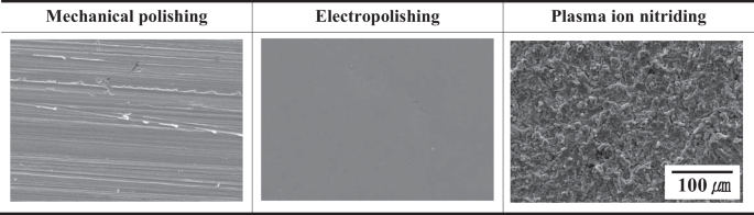
Surface analysis result by scanning electron microscope with surface treatment.
Figure 4 presents the graph of peak intensity for diffraction peak angles obtained using XRD. In Fig. 4a, γ austenite diffraction peaks on the (111) (200) (220) planes, corresponding to 2θ values of 43.6°, 50.8°, and 74.6°, respectively, were observed for the mechanically polished and electropolished stainless steel. However, an α’ martensite peak on the (111) plane corresponding to 44.6° was additionally confirmed in mechanically polished stainless steel. The peak intensity and width obtained from the XRD analysis were interpreted as follows. In the case of UNS S31603, the austenite phase has a relatively low nickel content, so a metastable phase may exist4. Accordingly, it is proposed that the metastable austenite phase is caused by martensitic transformation due to stress or strain generated during manufacturing or finishing treatment5,6. After electropolishing, the 2θ values of the diffraction peaks were consistent. However, the peak intensity increased, the width narrowed, and the martensite phase was removed. In general, the diffraction peak intensity increased as the constructive interference of X-rays increased23. In this investigation, the reason for the increased diffraction peak intensity after electropolishing is that the γ phase became more distinct as impurities and fine burrs were removed by the process. In addition, Bushroa et al. reported that the presence of microstress on the surface causes the diffraction peak width to broaden24. In this research, the narrowing of the diffraction peak width after electropolishing indicates the removal of microstress24.
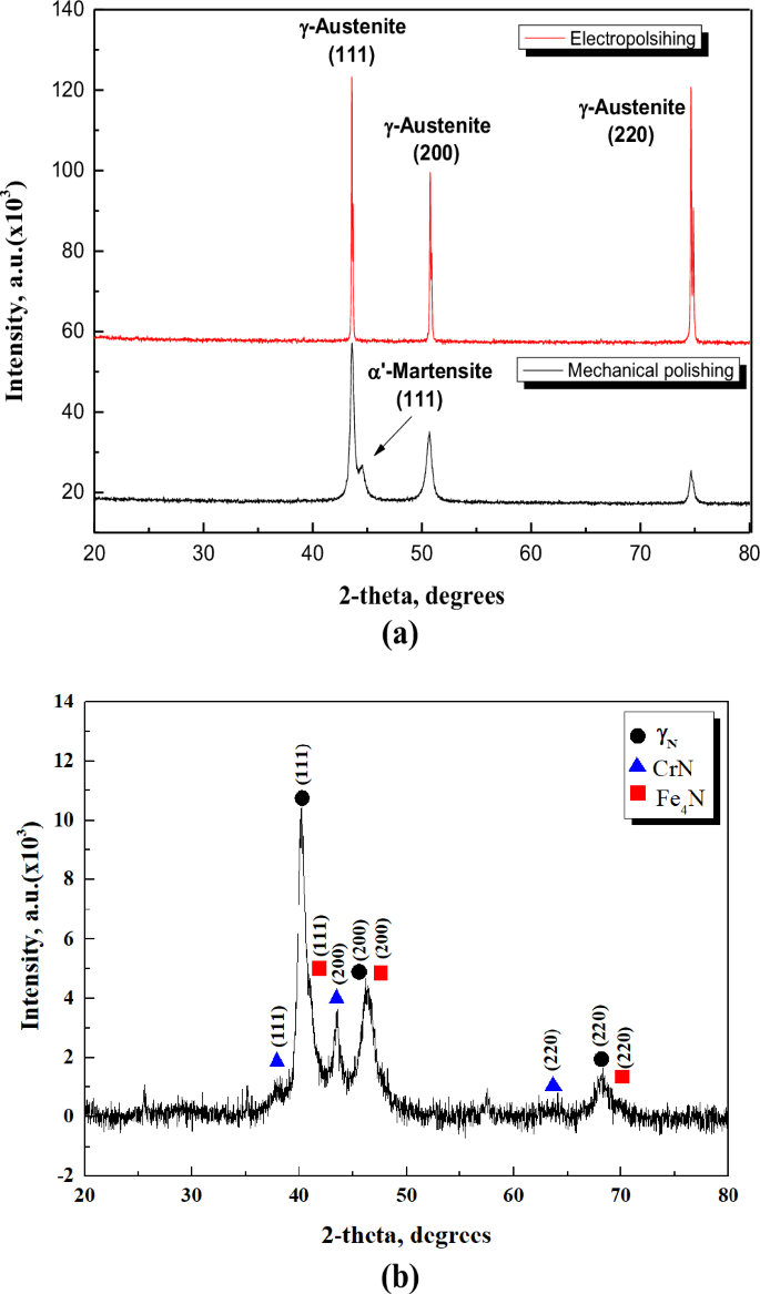
a Mechanical polishing and electropolishing. b Plasma ion nitriding.
In the case of plasma ion nitriding [Fig. 4b], γN diffraction peaks were observed at 2θ values of 40.4o and 46.1o and 68.1o. This is a crystal of expanded austenite (γN) corresponding to the (111), (200) and (220) planes. In addition, the (111), (200) and (220) plane of chromium nitride (CrN) is presented. And the (111), (200) and (220) plane of iron nitride (Fe4N) were measured at 41.1o, 46.8o and 69.9o. The width and size of the diffraction peaks of austenite were changed and shifted to a lower angle than those of the mechanically polished stainless steel. Based on the XRD data, the analysis was conducted as follows. This is suggested to be due to the high temperature during the plasma ion nitriding process caused by crystal size refinement and non-uniform strain25. Expanded austenite crystals were formed by the penetration of nitrogen atoms in a face-centered cubic lattice26,27,28. It has been reported that this supersaturated metastable phase increases wear resistance due to high hardness and affects corrosion resistance improvement26,27,28. However, the formation of chromium nitride in the plasma ion nitriding process reduces corrosion resistance, since chromium, which improves corrosion resistance, is precipitated as a nitride29. Expanded austenite (improved corrosion resistance) and chromium nitride (reduced corrosion resistance) are detected at the same time, so corrosion research with electrochemical characteristics is required.
Figure 5 presents the scanning electron microscope and EDS analysis results for the cross-section of plasma ion nitrided stainless steel. The layer formed of CrN, Fe4N and γN (below surface-treated layer) was distinguished from the base material using a marble etching solution (50 ml distilled water, 50 ml HCl, and 10 g CuSO4). This layer was measured with a thickness of approximately 9.21 μm and was densely formed without defects. Among the plasma ion nitriding process conditions, temperature and nitrogen flow are the main factors influencing the formation of the surface-treated layer30. The surface-treated layer was formed thick under appropriate process conditions and presented results corresponding to those of other researchers31. Furthermore, the surface-treated layer was separated by etching. According to Fernade et al., (a) is an expanded austenite layer and (b) is reported to be a chromium nitride layer32.
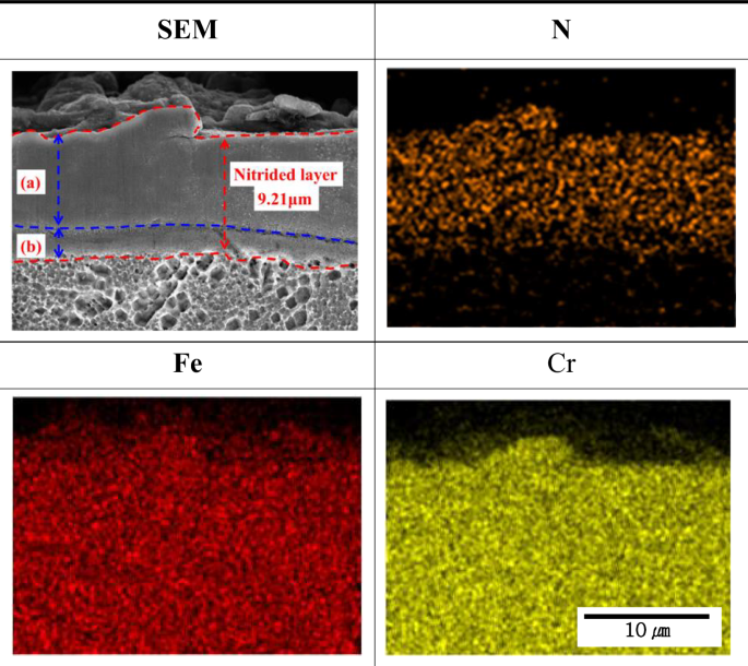
Result of cross-sectional EDS analysis of layer formed by the plasma ion nitriding.
Electrochemical experiment
Figure 6 is a polarization curve obtained via a cyclic potentiodynamic polarization experiment in scrubber washing water of 90 °C with surface treatment. Additionally, the chemical composition of the scrubber washing water is presented in Table 2. According to the research results of S. Esmailzadeha et al., the graph types are broadly categorized into three types33. These types are characterized by the reverse current density being greater than the forward current density (first type), smaller than the forward current density (second type), and equal to the forward current density (third type). The first type is referred to as a hysteresis loop. In this investigation, the polarization curves for all surface treatment conditions exhibited hysteresis loops. The corrosion behavior of this curve indicates that the damage formed by the potential applied in the forward direction progresses deeper when the potential is applied in the reverse direction.
In this investigation, the electrochemical properties were analyzed in terms of corrosion potential (Ⓐ), pitting potential (Ⓑ), vortex potential (Ⓒ), repassivation potential (Ⓓ), and transition potential from anode to cathode reaction (Ⓔ). In the case of the mechanically polished stainless steel Fig. 6a, the corrosion potential (Ⓐ), pitting potential (Ⓑ), and vortex potential (Ⓒ) in the forward scanning were observed to be −0.20 V, 0.11 V, and 0.52 V, respectively.
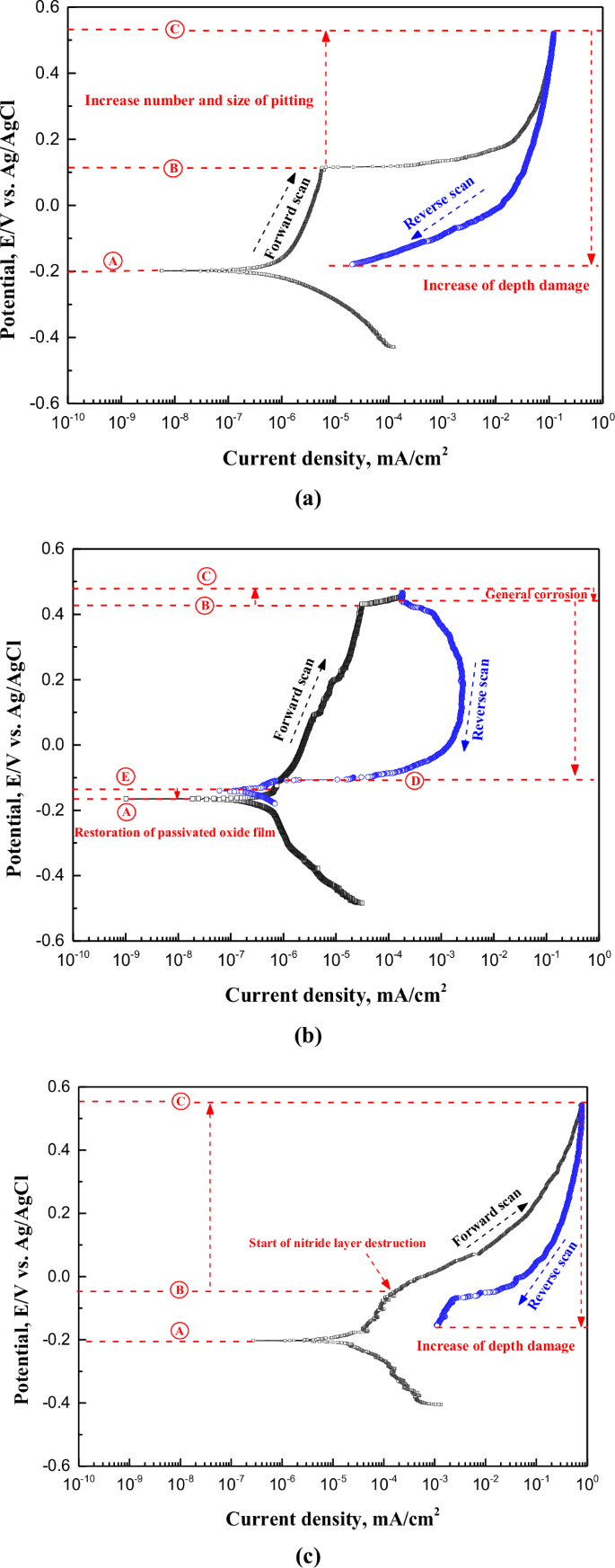
a Mechanical polishing. b Electropolishing. c Plasma ion nitriding.
The current density in the reverse scanning was higher than that in the forward scanning until the end of the experiment, which is the section where the previously generated damage grows in the depth direction. The corrosion potential and pitting potential in the case of electropolishing Fig. 6b increased by 0.03 V and 0.32 V, respectively, compared to mechanical polishing. In the reverse scanning, the repassivation potential (Ⓓ) and the transition potential from the anode to the cathode reaction (Ⓔ) were observed. For mechanical polishing, repassivation potential and anodic-cathodic transition potential were not observed. According to the research results of S. Esmailzadeha et al., when repassivation potential and anodic-cathodic transition potential are observed, the passive layer formed on the surface is dense and strong, exhibiting recovery (repassivation) behavior33. Accordingly, it can be concluded that the corrosion resistance of the passive layer was enhanced after electropolishing in this study. Additionally, for plasma ion nitriding, the current density sharply increased at -0.05 V. Generally, metals exhibiting passive characteristics present a rapid increase in current density when the passive layer is damaged. Therefore, it is considered that the layer formed by plasma ion nitriding was damaged at -0.05 V.
After electropolishing, the pitting potential of the stainless steel increased by 0.32 V compared to mechanical polishing, and the pitting resistance was improved. In addition, it is considered that the formation ability and durability of the passivation film are improved by presenting repassivation and the transition potential from the anode to the cathode reaction. Additionally, the reasons for the improved formation ability and durability of the passive film after electropolishing can be understood through the research results of K. RoKosz et al., which are as follows34. Following on from the results of XPS analysis by Rokosz et al., the passivation characteristics were improved by increasing the chromium and iron ion fractions on the surface after electropolishing34. In this way, it is judged that the formation ability and durability increased with the improvement of the passivation film characteristics in this investigation, corresponding to other researchers. In the case of plasma ion nitriding, expanded austenite suppresses local acidification due to the generation of ammonia by hydrolysis, as given in Eq. (2)35.
Accordingly, the autocatalytic process, which is a pitting damage mechanism, should be suppressed to reveal the repassivation effect; however, this was not observed in this research. This is considered to be due to the fact that the experimental solution and conditions were quite harsh, so that the repassivation characteristics did not appear.
Figure 7 depicts the damaged surface and weight loss after the cyclic potentiodynamic polarization experiment. In surface observations, the mechanically polished and electropolished stainless steel was found to have pitting and a relatively wide area of damage at the part in contact with the experimental holder. However, in the case of plasma ion nitriding, most of pitting occurred. However, in the case of plasma ion nitriding, pitting was observed both in the areas in contact with the experimental holder and in the other areas. The reason this damage tendency appeared when analyzed with the cyclic potentiodynamic polarization curve is as follows. In the case of the mechanically polished and electropolished stainless steel, the pitting occurrence rate was similar, but the occurrence rate of crevice corrosion was higher in mechanical polishing. From the pitting potential to the vortex potential (Ⓑ~Ⓒ) in Fig. 6, the number and size of pitting or crevice corrosion grew. In the case of the mechanically polished stainless steel, this section (Ⓑ~Ⓒ) is significantly longer than with electropolishing. Consequently, in the cyclic potentiodynamic polarization curves, the potential range and current density at which crevice corrosion occurs were observed to be greater for mechanical polishing compared to electropolishing. Therefore, crevice corrosion for the mechanically polished stainless steel was higher than that of electropolished stainless steel. In the case of plasma ion nitriding, since damage to the crevice area was hardly observed, it is determined that the pitting occurred more actively in this section (Ⓑ~Ⓒ). In the weight loss analysis, mechanically polished, plasma ion nitrided, and electropolished stainless steel were observed in the descending order of weight loss. Electropolished stainless steel is considered to have the lowest weight loss due to less occurrence of pitting and crevice corrosion. In the case of plasma ion nitriding, the reason the weight loss is similar to that of mechanical polishing is considered to be that damage to the surface-treated layer occurs at too low a potential.
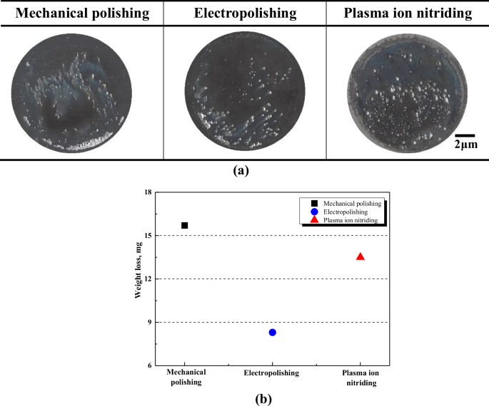
Appearance (a) and weight loss (b) after cyclic potentiodynamic polarization experiment in marine scrubber washing water.
Figure 8 is the result of calculating the corrosion potential and corrosion current density by Tafel analysis after the cyclic potentiodynamic polarization experiment. The corrosion potentials of stainless steel subjected to mechanical polishing, electropolishing, and plasma ion nitriding were calculated as −198.12 mV, −164.05 mV, and −202.75 mV, respectively. Electropolishing was the noblest and plasma ion nitriding presented the most active value. In the case of plasma ion nitriding, the lattice structure of iron is distorted by nitrogen penetration36. In addition, crystals grown in a granular structure may generate compressive stress and stacking faults37. It is proposed that the surface thus formed was unstable and exhibited the lowest potential. The corrosion potential of electropolishing presented the highest value due to the residual stress relief effect38. The corrosion current densities of mechanical polishing, electropolishing, and plasma ion nitriding were calculated as 1.125, 0.186, and 18.995 μA cm–2, respectively. The reason the corrosion current density of electropolishing is lower than that of mechanical polishing is due to the chromium content of the passivation film layer. Lee and Lai reported that the chrome area becomes thicker after electropolishing, and the ratio of Cr2O3 to Fe2O3 increases by 2.58 times39. Among the bipolar structures of the passivation film, the anion selective layer (Cr(OH)3) serves to transport oxygen ions to the surface40. Oxygen adsorbed on the surface reacts with chromium to form Cr2O3. It is suggested that the corrosion resistance is improved because the ratio of Cr2O3 is increased by the abundance of chromium41.

Corrosion potential (Ecorr) and corrosion current density (Icorr) by Tafel analysis after cyclic potentiodynamic polarization experiment with surface treatment in marine scrubber washing water.
The reason for the highest corrosion current density of plasma ion nitriding is considered to be due to the chromium depletion and the change of crystal structure. The CrN formed on the surface-treated layer depletes the chromium around it and affects the generation of the passivation film. CrN locally obstructs the diffusion of oxygen, hindering the uniformity and integrity of the passive film42. Additionally, areas containing CrN form micro-galvanic cells, which affect the uniform formation of the passive film43. For these reasons, CrN negatively impacts the formation of the passive film, leading to reduced corrosion resistance. In addition, the binding energy of CrN formed with expanded austenite is lower than that of Cr2O341,44,45. Binding energy indicates chemical stability with the electronic composition of d orbitals, so it is an indicator of oxidation tendency. It is considered that CrN and Cr2O3 affect the corrosion rate due to different binding energies.
Figure 9 is the scanning electron microscope observation result of the central (a) and crevice (b) areas after the cyclic potentiodynamic polarization experiment. The surface-treated specimens were locally damaged by chloride ions and sulfate ions in the central area. The chlorine ions have a greater effect on passivation film destruction than other halogen elements46. This is because the absolute value of the Gibb’s energy for hydrating the passivation film is the largest. Accordingly, corrosion starts first on an unstable surface of passive film with relatively high thermodynamic energy, resulting in damage of the form of local corrosion. Due to this local corrosion, grain boundaries were observed inside the damaged area (area I). In the case of mechanical polishing and plasma ion nitiriding in the edge area of local corrosion, lace-shaped damage was observed47. This type of damage is so named because it resembles a lace-like thin leaf-shaped decoration and is micro-sized48. According to Ernst et al., this corrosion damage is produced by metastable pitting, in which the continuous growth of pitting nuclei and the repassivation of the passivation film work together49. As such, the lace shape has a potential role in extending the pitting because it arises around the pitting49. Therefore, it is considered that mechanical polishing and plasma ion nitriding are more likely to expand pitting than electropolishing.
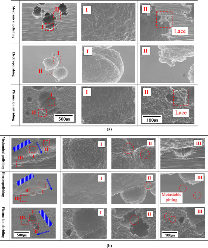
a Center area. b Crevice area.
Following observations of the damage area generated in the crevice area, the width of the damage was observed to be widest in the order of mechanical polishing, electropolishing, and plasma ion nitriding. Wu et al. divided crevice corrosion into crevice entrance, general damage inside the crevice, propagation, and crevice corrosion inducing area50. Accordingly, in this investigation, the crevice area was analyzed by dividing it into I, II, and III. In the I area, ion exchange with the outside is difficult at the beginning, and crevice corrosion begins. However, over time, it exceeds the critical size of crevice corrosion and grows in the depth direction because ion exchange is easy. In area II, crevice corrosion propagates with the metastable pitting, and damage is extended. In the case of the three surface-treated specimens, areas I and II presented similar trends. However, a different trend was observed in area III. Area III is the farthest part from the area where the initial crevice corrosion started. If the metastable pitting is observed in this area, it indicates the possibility of crevice corrosion expansion. In the case of electropolishing and plasma ion nitriding, it is suggested that the damage will expand in the width direction (Horizontal direction based on metal surface) as metastable pitting is observed. However, in the case of mechanical polishing, no clear metastable pitting was observed, and it was judged that the damage would grow in the depth direction (Vertical direction based on metal surface).
Figure 10 is the result of 3D laser microscopic analysis of the central (a) and crevice (b) areas after the cyclic potentiodynamic polarization experiment. In all surface treatments, similar pitting was observed in the central area. The roughness after electropolishing and plasma ion nitriding were reduced by 20.28 μm and 7.61 μm, respectively, compared to mechanical polishing. The maximum damage depth after electropolishing and plasma ion nitriding were reduced by 110.13 μm and 46.59 μm, respectively, compared to mechanical polishing. As seen in observations of the crevice area, both the width and depth of crevice corrosion after electropolishing were reduced compared to mechanical polishing. In addition, in the case of plasma ion nitriding, the tendency of pitting rather than crevice corrosion was clearly observed. The surface treatment applied in this research is judged to be effective in suppressing crevice corrosion. In general, stainless steel is inhibited from local corrosion by the anion selective layer (Cr(OH)3) generated by Eqs. (3) and (4)51.
In the case of electropolishing, it is suggested that the pitting resistance is improved by increasing the chromium hydroxide (Cr(OH)3) fraction in the passivation film52. Also, in the case of plasma ion nitriding, nitrate ions generated by Eq. (5) promote the formation of a cation selective layer (MoO4n−)53.
It is suggested that the damage was reduced because the formed cation selective layer inhibited the permeation of chloride ions53. The roughness of plasma ion nitriding was smaller than that of electropolishing, which is considered to be due to width damage. However, the maximum damage depth of plasma ion nitriding was not significantly reduced compared to mechanical polishing. Overall, the electropolished stainless steel demonstrated the best resistance to local corrosion.
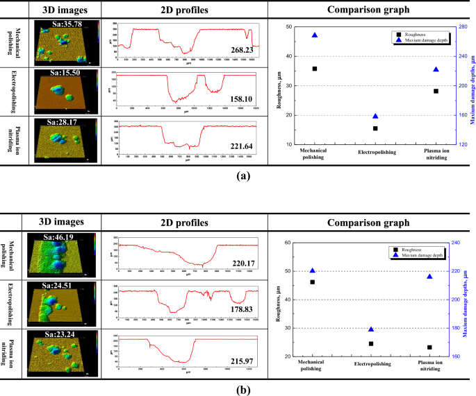
3D images, 2D profiles and comparison graph for center area (a) and crevice area (b) after cyclic potentiodynamic polarization experiment in scrubber washing water treatment (Unit: μm).
Figure 11 is a schematic diagram depicting the corrosion damage mechanism during the cyclic potentiodynamic polarization experiment. The corrosion process was analyzed by dividing it into the initial state and forward and reverse scanning cases.
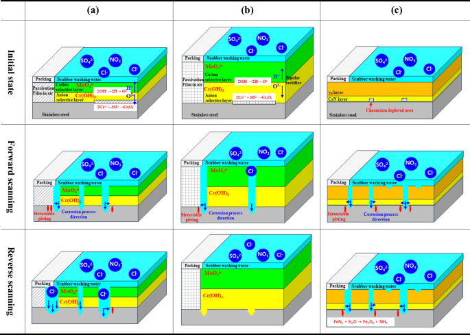
a Mechanical polishing. b Electropolishing. c Plasma ion nitriding.
In the case of mechanical polishing, a passive film was formed on the stainless steel surface in the air before the experiment. The initial state indicated that the specimen was placed in a holder and immersed in washing water. The area in contact with the holder packing is a passive film formed in the air. In addition, the passivation film of stainless steel containing molybdenum in the area in contact with the washing water, which is the experimental area, presents a bipolar structure (cation selection layer (MoO4n−) and anion selection layer (Cr(OH)3)). The cation selection layer suppresses the penetration of aggressive anions (chlorine ions, sulfate ions) in the washing water and releases hydrogen ions, which are cations generated inside (cation selection layer), to the outside (scrubber washing water). The anion selective layer promotes the formation of a chromium oxide film by moving oxygen ions to the metal surface. In the forward scanning, the metastable pitting occurs in the central area and the crevice area where the packing meets, and the damage proceeds in the depth and width directions. In the reverse scanning, the crevice area exceeds the critical size of crevice corrosion, and damage occurs in the depth direction. However, in the central area, the damage grows in both the depth and width directions due to the continuous formation of metastable pitting.
In the case of electropolishing, in the initial state, the passivation film layer is formed thick and dense with a higher percentage of chromium fraction than mechanical polishing. In the crevice area in the forward scanning, the metastable pitting is observed as in mechanical polishing, and the damage grows in the depth and width directions. However, the metastable pitting does not occur in the central area, and local corrosion grows in the depth direction. Since the repassivation potential and the transition potential from the anode to the cathode reaction were observed in the polarization curve in the reverse scanning, the passivation film was recovered, and the electrochemical properties are excellent.
In the case of plasma ion nitriding, an expanded austenite layer and a chromium nitride layer were observed in the initial state. Due to the process of forming the chromium nitride layer, a chromium depleted area was generated. It is suggested that the damage started in the chromium depleted area with relatively weak corrosion resistance in the forward scanning. In addition, the metastable pitting was observed in the central area and the crevice area, so that the damage progressed in the depth and width directions. Moreover, in the reverse scanning, ammonia produced by hydrolysis of expanded austenite should suppress local acidification, but local damage continues to progress in the crevice and the central region due to the harsh experimental environment.
As a result, electropolished stainless steel has greatly improved corrosion resistance, and pitting resistance and is considered to be a suitable technology for scrubber application.
Experimental method
Specimen and electropolishing
In this investigation, UNS S31603 austenitic stainless steel was used. The chemical composition is 16.70 wt% Cr, 0.012 wt% N, 2.03 wt% Mo, 10.19 wt% Ni, 0.023 wt% C, 0.60 wt% Si, 1.05 wt% Mn, 0.034 wt% P, and 0.282 wt% Cu, with the balance being comprised of Fe. The pitting properties of stainless steel can be compared using the pitting resistance equivalent number, which was calculated as 23.6 according to the calculation formula (%Cr + 3.3%Mo + 16%N)54. This is a stainless steel typically used in the marine industry55.
The specimen was processed with an exposed area of 4 cm2 using a fine cutter, and thermal deformation was minimized by supplying cooling water during processing. The processed specimen was subjected to mechanical polishing using emery paper #220. The polished specimen was ultrasonically cleaned using acetone and distilled water, and electropolishing was performed after complete drying. The electropolishing process was performed for seven minutes by applying a current density of 300 mA cm–2 in an electrolyte in which sulfuric acid and phosphoric acid were mixed at a volume ratio of 4:6 at 75 °C. This is the optimal condition in accordance with Taguchi robust design56.
Plasma ion nitriding
The specimens for plasma ion nitriding were connected to the cathode, and the wall of the vacuum container was composed of the anode to generate a DC glow discharge. The plasma ion nitriding process consists of a vacuum exhaust, heating and elevated temperature, nitriding, and cooling by glow discharge. In addition, the temperature, pressure, and voltage in the chamber were maintained by an automatic control system, and argon was used as a catalyst gas. A cathodic sputtering process was performed to remove impurities and oxides formed on the surface before plasma ion nitriding. Table 1 presents the detailed conditions of the cathodic sputtering and plasma ion nitriding process.
Electrochemical experiment
The electrochemical properties of the electropolished and plasma ion nitrided specimens were investigated using a cyclic potentiodynamic polarization experiment (GAMRY, Interface 5000) in scrubber washing water of 90 °C. In the case of the cyclic potentiodynamic polarization experiment, the potential is set in the forward and reverse directions, unlike the potentiodynamic polarization experiment in which the potential is applied only in the forward direction. In the cyclic potentiodynamic polarization curve, repassivation potential, hysteresis curve, and anodic-cathodic transition potential are observed with the reverse behavior, which is very effective in investigating the behavior of localized corrosion. In particular, it is easy to analyze the passivity characteristics of passivation films and coating layers. Therefore, because the scrubber washing water is a seawater-based solution that causes localized corrosion, this investigation applied a cyclic potentiodynamic polarization experiment. The composition and characteristics of the washing water (experimental solution) are given in Table 2. The experimental solution was a solution obtained by washing the exhaust gas generated by operating the engine using bunker C fuel at 75% load for one hour with a scrubber. The engine used was a MAN B&W, a two-stroke cycle crosshead-type diesel engine. The engine has six cylinders, and the bore and stroke lengths are 460 mm and 1932 mm, respectively. Power, speed, and maximum pressure (Pmax) are 7400 kW, 129 rpm, and 150 bar, respectively, in terms of the specified maximum continuous rating (SMCR). The cyclic potentiodynamic polarization experiment utilized a three-electrode cell. A silver/silver chloride (Ag/AgCl saturated 3.3 M KCl) electrode and a platinum (Pt) electrode were used as the reference electrode and counter electrode, respectively. The cyclic potentiodynamic polarization experiment started at −0.25 V as an open circuit potential standard, and when it reached 0.7 V (vs. Ag/AgCl), it was scanned to the open circuit potential in the reverse direction. The scan rate was set at 0.5 mV s-1, and the corrosion potential and corrosion current density were calculated by Tafel extrapolation with respect to the polarization curve obtained after the experiment.
Specimen surface analysis
After surface treatment, the phase analysis was performed with an X-ray diffractometer (RIGAKU, SmartLab). All surface-treated specimens exhibited Cu Kα radiation with λ = 1.546 Å in the range of 2θ = 20o ~ 80o (step size = 0.02o, step time = 1.0 sec step-1). The crystal structure was analyzed by comparing the obtained XRD data with the ICDD data file. The thickness and elements of the layer formed by CrN, Fe4N and γN were analyzed using EDS (OXFORD, AZTec Energy) for the cross-section. In addition, the surface before and after the electrochemical experiment was analyzed with a 3D laser microscope (OLYMPUSTM, OLS5000 LEXT) and a scanning electron microscope (SEC, SNE-4500M Plus).
Responses