Chemical and electrochemical pathways to low-carbon iron and steel
Introduction
Globally, about 1.85 billion tons of steel are produced annually1,2. For every ton of steel, 1.8–2.0 tons of CO2 are generated3,4. Thus, the iron and steel industry is one of the leading sources of anthropogenic emissions, currently responsible for about 24% of industrial CO2 emissions5,6,7. With the iron and steel industry forecasted to grow up to 2.5–3.0 billion tons by the year 2050, this number is poised to rise unless new low carbon practices are adopted1.
The majority of emissions arise from the iron ore reduction step, which is usually performed in a carbothermic blast furnace (BF) utilizing coal and natural gas (Fig. 1)6. Over 70% of total steel production, or over 2.6 billion tons of iron ore, are processed by BFs annually6,8,9,10. To meet emissions reduction targets and mitigate climate impacts, development of a BF alternative is imperative.
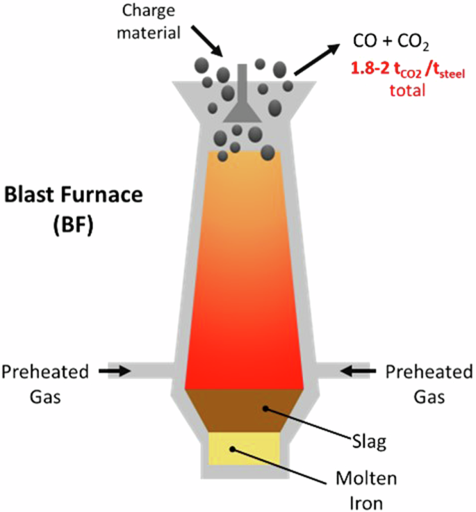
Illustration of blast furnace (BF) operation.
Groundbreaking low-carbon solutions that can be scaled without compromising supply are needed9. Currently, the alternative processes utilized by industry, including direct reduction (DR) and smelting, still rely on fossil fuels. For example, while cleaner than BFs, the DR route still produces 0.7–0.9 tons of CO2 and consumes over 10 GJ of energy per ton of primary steel produced11,12. These processes also have various limitations. DR can only accommodate high-grade ores. Smelting processes are the most energy-intensive of all commercially relevant approaches due to heating demands7.
To date, the most successful effort to reduce emissions has occurred through increased scrap utilization in electric arc furnaces (EAFs). In the United States, scrap utilization has been successfully deployed at scale and has decreased the emissions of the U.S. steel industry to 1.0 ton CO2 emitted per ton of steel5. However, EAF steelmaking currently relies on significant quantities of carbon intrinsic to metallic charge and otherwise injected. Thus, EAFs still emit a significant amount of CO213. Furthermore, scrap recycling is limited by a buildup of copper, which is difficult to remove from scrap and causes hot shortness, so primary iron is still needed to dilute copper in the scrap stream. Also, high-grade products such as automotive sheet steel cannot be produced from conventional scrap14. Finally, scrap supply is not sufficient to meet overall steel demand13. For these reasons, primary iron production still constitutes 30% of U.S. production, and the United States imports over $3.0 billion worth of virgin iron from Ukraine, Russia, and other sources15,16, making it one of the world’s largest iron importers. While scrap utilization has been very successful in reducing U.S. emissions, scrap steel utilization alone is not a viable path toward reaching net-zero goals.
Ultimately, reaching net-zero goals will require deployment of new technologies. Here, we present promising chemical and electrochemical alternatives to current carbon-intensive practices. These include hydrogen direct reduction (H2DR), which is already being deployed at scale by SSAB, H2 Green Steel, and others and is relatively mature, building off the current DR process. We also discuss hydrogen plasma smelting, hydrogen smelting, and ammonia-based reduction, which are less mature but promising routes8. In addition to chemical reduction, we discuss electrolytic approaches that could directly utilize green electricity to produce iron. Finally, we discuss using biocarbon or carbon derived from CO2 in EAFs, completing the path from green iron to green steel. As these low-carbon technologies all rely on low-carbon electricity, either directly or for hydrogen production, we have also included discussion of renewable energy integration.
Background
Blast furnaces (BF) reduce iron ore (usually hematite, Fe2O3) to molten metallic iron. They are vertical shaft furnaces into which charge materials including ore, reducing agents (usually coking coal), and fluxing agents (such as limestone, added to control slag formation and properties) are fed from the top (Fig. 1). Pressurized pre-heated oxygen-enriched air at a temperature between 900 °C and 1250 °C is introduced through tuyeres in the lower part of the furnace, resulting in the combustion of coke and coke gasification:
Coke gasification (2) has a positive ΔH⁰ and is thus endothermic. It reaches a negative ΔG⁰ only above 970 K, as the increase in the number of moles of gas leads to the positive TΔS⁰ term dominating at high temperature. Below this temperature the reverse process, sooting, is favored, so the equilibrium ratio of CO to CO2 is highly temperature dependent17.
As the carbon monoxide produced in the active coke zone (near the bottom of the BF) rises through the furnace and contacts the ore, the following reactions occur:
This cascade of reduction reactions results in a reduction of the remaining solid volume, which causes previously dense iron ore to become increasingly porous as reduction occurs.
At temperatures above 1650 K, ΔG⁰(T) abruptly becomes more negative as FeO melts. Molten iron and slag accumulate and drip down through the coke bed to the hearth to form the liquid iron and slag. The molten FeO is then reduced:
Thus, CO serves as the reducing agent, producing CO2.
Reaction kinetics in a BF are determined by multiple factors. For reactions with solid ores, these include mass transfer of reducing gas from the ore surface to the bulk, diffusion-based mass transfer of reducing gas into the porous reducing/reduced layer, and chemical reaction kinetics of the reaction between the oxide phases and reducing gas. Variable conditions within the BF affect reaction kinetics, including temperature, gas oxidation degree (the ratio of oxidized gas components over the sum of oxidized and oxidizable components).
An additional, relatively minor, source of CO2 in many steelmaking processes come from the use of certain fluxes. Reactions such as the decomposition or synthesis of high calcium or dolomitic (contains Mg and Ca) lime fluxes also contribute to total CO2 emissions as follows:
Several strategies are increasingly being implemented to increase BF efficiency as much as is possible. These include augmentation of coke with lower carbon materials such as pulverized coal and natural gas oxygen-enriched BF operation (oxygen BF process), which results in decreased total energy consumption, and top gas recycling, in which the residual reducing agents in the gas coming off the BF are reheated and reinjected into the BF10,18,19,20. While these methods help improve efficiency of BFs, there are fundamental limits to how much the energy and carbon intensity of coal- and natural gas-based ironmaking processes can be reduced.
Direct Reduction (DR) processes, which have emerged as a BF alternative, reduce iron ore to metallic iron which remains in a solid state. The product, direct reduced iron (DRI), is then further processed in an EAF (Fig. 2). Currently, over 120 Mt steel per year is produced via this route, often using shaft furnaces, although rotary kilns, rotary hearth furnaces, and fluidized bed reactors are also options21,22. The reducing gas used in conventional DR is rich in carbon monoxide and hydrogen, and is made by partially oxidizing natural gas in a reformer. Reforming proceeds via the following reactions for methane, which is the primary component of natural gas:
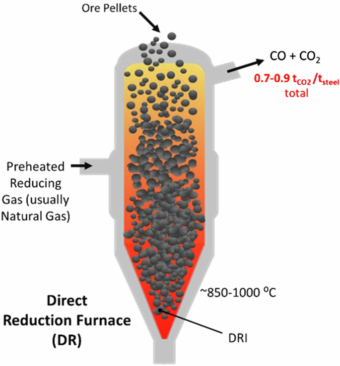
Illustration direct reduction furnace (DR) operation.
Both Eqs. 9 and 10 are endothermic, and these reforming reactions are performed at around 1100°–1500 °C. This temperature is often achieved via combustion of about one-third of the total natural gas. Some fraction of the emission CO2 from this heating are typically recycled and added to steam in the reformer so that both dry and wet reforming reactions occur simultaneously in the reformer23.
During DR, hematite converts first to magnetite (reaction 3). Due to the kinetics of competing reduction reactions, subsequent reduction of magnetite occurs via temperature dependent pathways. At temperatures below 570 °C, magnetite converts directly to iron:
However, at temperatures above 570 °C, magnetite is reduced to wüstite (FeO) before being further reduced to metallic iron (reactions 4 and 5)21.
The overall process of iron reduction in a DR is exothermic and is largely driven by reaction with CO. However, the hydrogen gas participates as well, such that the reaction temperatures ~850°–1000 °C differ somewhat from the temperatures that would be predicted by a thermodynamic analysis of the above reactions. Despite the participation of H2, the exothermic reaction with carbon monoxide is the key reaction that allows the DR process to proceed without supplementary heating.
Importantly, DRI produced by DR with natural gas is carburized, usually containing 0.5–4 wt% carbon12. This carburized DRI is suitable for subsequent processing in an EAF. This carbon is important because it affects the melting and foaming of the DRI in the EAF.
Complex mathematical models across multiple size scales have been developed to describe and optimize kinetics of DR furnace operation. For example, at the scale of a single pellet of ore, these include the shrinking core model, which assumes that reaction kinetics occur via formation of an outer shell of metallic iron, which grows radially into the core until the entire oxide is reduced, and the grain model, which accounts for gas diffusion into the ore by assuming reduction takes place in a larger region of the oxide, rather than just the surface.
Smelting reduction is also used to reduce iron ores, albeit on a smaller scale than BFs or DRs. In the 1990s, direct iron smelting reduction processes emerged as an alternative to BF processes for making molten, slag-free iron. The main feature of smelt reduction is that pre-reduced iron ore is reduced by char generated from coal to form molten metal and slag7. Currently, the main incentive behind smelting reduction is to produce hot metal from low-grade ore, often without pelletization. Pelletization, a pre-processing step where concentrated ore is formed into pellets at elevated temperatures, requires higher grade ore and is a common agglomeration step for DR iron making11. Thus, smelting reduction is advantageous in that it produces a premium product and can accommodate alternative and low-grade feedstocks. However, it still utilizes carbon-intensive carbothermic reduction with associated CO2 emissions. Furthermore, the smelting furnace must reach at least 1500 °C; these high heating demands make smelt reduction energy-intensive, requiring over 18 GJ of energy per ton of steel produced7.
Discussion
One promising route for decarbonization is use of alternative chemical reductants in place of carbon-based, fossil-fuel derived reductants. The most promising theoretical low-carbon alternative reductant to fossil fuels is hydrogen, which, according to Bhaskar et al. 21 has the potential to reduce emissions by 2.3 Gt of CO2 per year compared to the current baseline if used to replace existing iron reduction technologies. Hydrogen’s viability as a reducing agent is illustrated in the Ellingham diagram in Fig. 3. The Ellingham diagram provides a measure of ΔG⁰ as a function of temperature. In principle, species lying lowest in the diagram can reduce the oxides above. Thus, it can be seen that above certain temperatures, C and CO can reduce iron species. However, hydrogen is also capable of doing so. The hydrogen line lies below the Fe2O3 line at all temperatures, and below the line of Fe3O4 above ~600 °C, indicating that it can, in principle, reduce these iron oxides above 600 °C. While the H2 line is above the FeO line, indicating that H2 is an unfavorable reducing agent for FeO, the proximity of the two lines means that, in practice, H2 can reduce FeO to Fe but this reduction halts at a certain H2O/H2 ratio24. Thus, it requires a large flow of H2 or other approaches, such as generation of more reducing monatomic H gas (the lowest-lying line in Fig. 3) via plasma-based approaches.
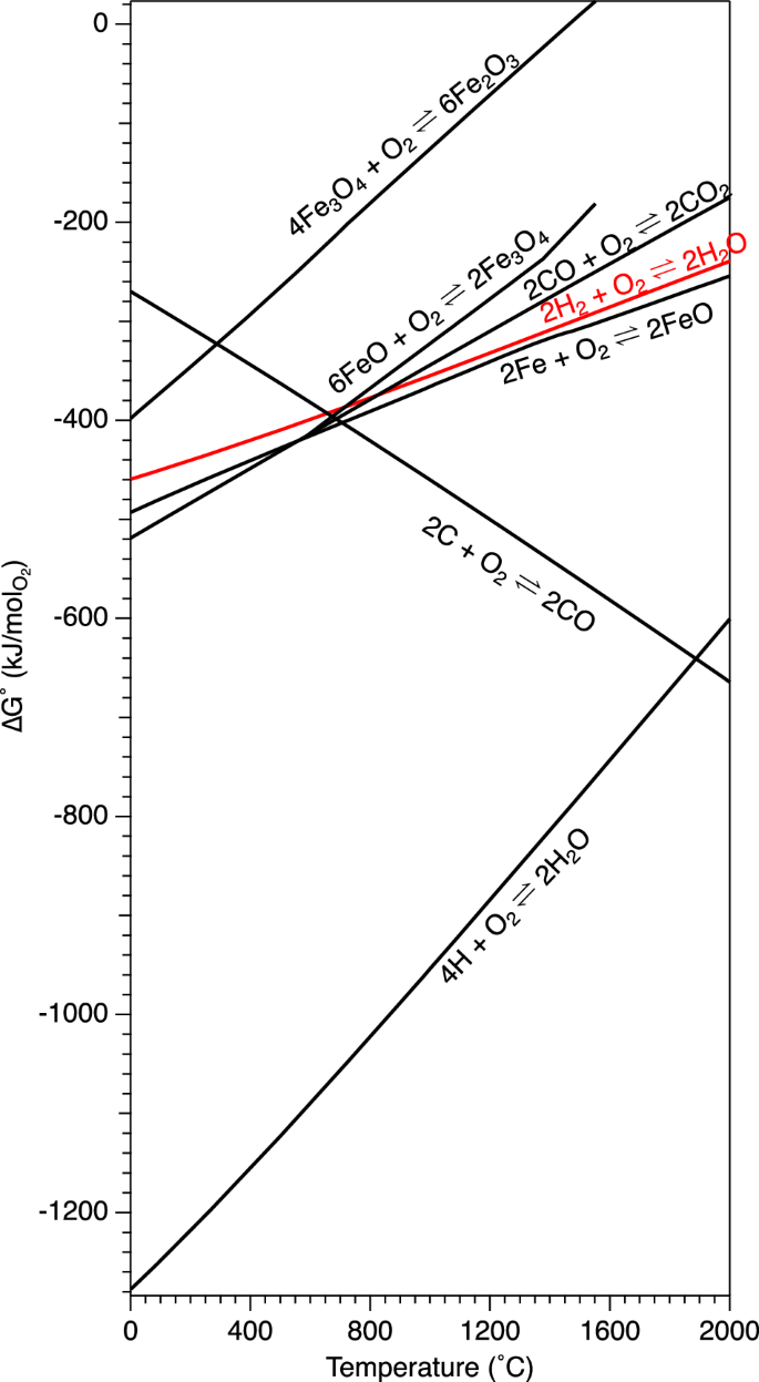
Monatomic H is found as a radical in many H2-plasma systems. Calculated using thermochemical parameters from ref. 80.
Further insight into the reduction of iron with carbon and hydrogen reducing agents can be gained from the Baur-Glässner diagram6. In this diagram, shown in Fig. 4, the different stable iron oxide phases are given according to temperatures and gas oxidation degree. The gas oxidation degree can provide an indication of the reduction force of the gas—a higher gas oxidation degree represents a less reducing gas. This is because the composition of the gas is one of the most important factors in controlling reduction.
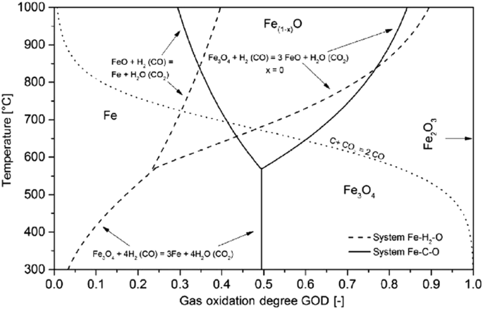
From ref. 6.
As is illustrated by Fig. 4, H2 reduction is best performed at the highest practical temperature, because the region of stability of iron expands to encompass higher gas oxidation degrees as temperature increases, allowing an increased theoretical gas utilization. This is in contrast to CO, for which the iron stability region decreases beyond a certain temperature. In other words, at 810 °C, both gases have the same reduction potential. At higher temperatures, the reduction potential of H2 is better than CO, and at low temperatures the reverse is true.
There are several promising approaches for reduction using hydrogen. We identify three leading pathways that could have substantial impact on steel emissions due to their low CO2 emissions, theoretical viability, and potential scalability: (1) hydrogen-based direct reduction (H2DRI), (2) hydrogen plasma reduction (HPR), and (3) hydrogen smelting.
Direct Reduction with Hydrogen (H2DRI) is widely considered an extremely promising route to decarbonized iron production. It is a natural extension of a current industrial process (DR). Thus, relative to other technologies, deployment of H2DRI may require lower capital investment, less novel design and engineering, and less change to existing operations. H2DRI is, in principle, quite similar to the natural gas-based DRI depicted in Fig. 2, except with hydrogen alone as a reducing gas. Similar to reduction with carbon monoxide in natural gas-based DRI, reduction of iron oxide (in the reactions below, hematite) does not proceed directly to iron, but goes through a series of temperature-dependent reactions. First, reaction occurs to form magnetite (Fe3O4):
At temperatures below 570 °C, magnetite is further reduced directly to iron via6:
However, above 570 °C, wüstite (Fe1-xO) is stable and must also be considered, leading to reactions25,26:
Where x represents the Fe deficiency of wüstite, leading to a nonstoichiometric compound where the equilibrium ratio of Fe to O is governed by temperature and pO2 dependent concentrations of Fe vacancies and interstitial Fe26. Significantly, reduction of these iron oxide phases with hydrogen is only mildly exothermic for the initial reduction of hematite (Eq. 12), and much more endothermic across subsequent reduction steps (Eqs. 13–15), resulting in a net endothermic reaction6. Thus, supplemental heating is required for thermal management of H2DRI.
Similar to the fossil fuel-based reduction methods described above, the kinetics of H2 DR reactions rely on mass transfer of the gaseous species through the laminar layer at the oxide surface to the interface, mass transfer based on diffusion into the ore through pores, and chemical reaction kinetics including nucleation and growth of iron species6. Thus, the rate-limiting step varies depending upon conditions.
For example, the chemical reaction rate of iron reduction is correlated strongly to temperature. At low temperatures, it is often the rate limiting step. However, if the ore has extremely low porosity or if a dense iron layer forms around the ore, preventing diffusion, mass transfer of the gaseous species into the pores may be the rate limiting step, even at low temperatures. In another scenario, when reaction becomes very fast, unconstrained by temperature or pore size, mass transport of the gas at the interface becomes the rate limiting step.
Recently, O’Malley and Seetharaman et al. 27,28 conducted studies of H2DRI reduction. They studied ore pellet reduction and found that increase in temperature, increase in gas flow rate, increasing hydrogen content (compared to carbon monoxide), and decreasing pellet size all resulted in increased reduction rate. Interestingly, porosity increased with degree of reduction.
Results from O’Malley and Seetharaman et al. are consistent with previous results by El-Geassy and Nasr29,30 indicating that increased temperature increases reaction rate. This correlation between high temperature and high reduction rate agrees with theory, as the rate of diffusion and phase boundary reactions increase with temperature. Furthermore, the Baur–Glässner diagram shows that for reactions with hydrogen, the driving force of the chemical reaction increases with temperature, so for reduction with hydrogen, higher temperature is both kinetically and thermodynamically favorable. Results from O’Malley and Seetharaman et al. are also consistent with results from ref. 31 who showed that complete reduction was achieved faster using hydrogen than carbon monoxide. According to Turkdogan and Vinters32, the increased kinetics of H2 reduction relative to CO reduction is likely due to differences in gas diffusivity.
While H2DRI is a promising research avenue that is currently being deployed at scale9,33, significant hurdles remain before widespread adoption is feasible. These include thermal management, ore feedstock limitations that are correlated to post-processing in an EAF, and issues with H2DRI including lack of carburization and cracking during reduction.
The endothermic nature of the reaction with hydrogen necessitates an altered thermal management strategy compared to natural gas-based DR, and is an issue that has yet to be solved at scale. Without an exothermic reaction, a large amount of extra heat is needed, or the materials in the shaft rapidly cool, resulting in inefficient reduction, reduced productivity, and higher cost. Strategies proposed by Chevrier34 include injection of natural gas (increasing emissions), addition of a heat carrier gas that is a better heat transfer media than hydrogen (such as nitrogen), and overblowing H2 (flowing more H2 into the reactor than necessary to facilitate heat transfer, possibly causing issues with gas velocity controls35 and decreasing energy efficiency), but further research into these strategies is needed.
Iron ores always contain gangue, though the type and amount vary based on the source location and the beneficiation process. Typically, some fraction of oxides such as SiO2, CaO, MgO, and Al2O3 remain6. To ensure successful processing in EAFs, H2DRI must utilize high-grade, iron-rich (Fe >65% by mass) hematite feedstock with low-gangue content, which necessitates either use of only the highest grade ore, which is in scarce supply globally and does not align with U.S. resources, or complex, expensive, and energy-intensive beneficiation36. Research to improve beneficiation could help address this. For example, Mlinar et al. 37 have demonstrated success in removing quartz, apatite, and gangue from iron ore resources via a flotation process. Another solution being advanced by Hatch is development of electric smelting furnaces (ESFs), which could be used to process H2DRI from lower-grade ore38.
Compared to DRI pellets produced with natural gas, H2DRI pellets are more challenging to process39. One reason is that, while unreduced pellets typically have a higher compressive strength than reduced pellets, the strength of H2DRI pellets is significantly lower compared to conventional DRI. Figure 5 illustrates cracked H2DRI pellets. Because compressive impacts are common during handling, stockpiling, and shipping, this is problematic, leading to breakdown into undesirable fines and potentially causing loss of material39. There have been reports suggesting that fragility likely results from swelling during reduction, as profuse cracks form and porosity increases, decreasing compression strength. Experimental results suggest that the presence of carbon monoxide contributes to strength development, preventing crack profusion, which is lacking in H2DRI. Unfortunately, Taniguchi and Ohmi40 demonstrated that sintering of H2DRI at a later stage is not effective for strength recovery. Higher gangue content limits swelling, but because lower gangue content is desirable, this is not a viable solution. Water vapor also appears to limit swelling, likely because it activates diffusion of oxides present in gangue, but the effect is not as significant as the use of carbon monoxide39. Further research into this topic may help elucidate and mitigate swelling mechanisms.
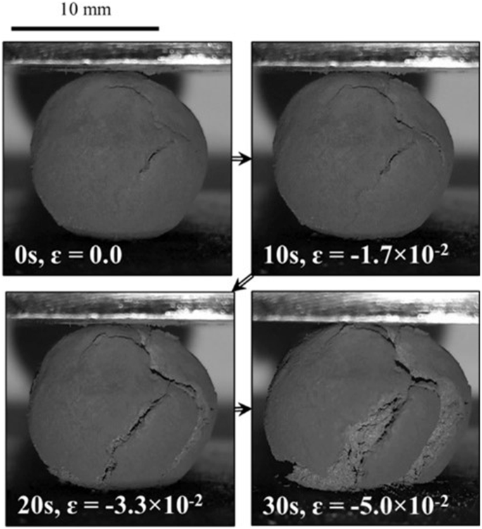
Reproduced from refs. 39,41.
Another challenge presented by H2DRI is the lack of carburization. H2DRI is carbon-free, whereas DRI produced with natural gas contains carbon, which changes its melt properties and is partially oxidized in the EAF, contributing to slag foaming energy. Also, carbon-free H2DRI is more easily reoxidized and difficult to store41. Several strategies have been proposed to address this, including carburization with a small amount of natural gas (with higher emissions), and use of biocarbon.
Given the differing properties and lack of carburization in H2DRI, steelmaking will have to be optimized for compatibility with H2DRI. In particular, EAF operation with H2DRI must be adjusted. Optimized melting and foaming of charge, slag preheating, smelting, and coupling to upstream heating are all options that could be explored to mitigate issues associated with different melting and foaming behaviors of H2DRI.
HPR is similar to the hydrogen-based methods described above, except instead of reduction by gaseous hydrogen, reduction is accomplished by hydrogen ions from plasma (a different state of matter), as well as radicals and other energetic species generated from the plasma process. There are many ways to initiate a plasma. Plasma arc discharges can be generated in direct current (DC), alternating current (AC), or radiofrequency (RF) modes8,42. Species present in all types of plasmas include electrons, radicals, ions, photons, and vibrationally and rotationally excited species. These species are formed through a combination of elastic and inelastic collisions.
Generally, plasmas are classified as thermal and non-thermal plasmas based on the gas temperature, as illustrated in Fig. 6A. Thermal plasmas often occur at pressures ≳1 atm and involve a high rate of collisions. So, although the electrons heat most quickly, the heavier species rapidly equilibrate, reaching local thermodynamic equilibrium in a typical range of 5000 K to 25,000 K. These thermal plasmas are used for arc welding, plasma spraying, plasma cutting, arc furnaces, and other metallurgical applications. In contrast to non-thermal plasmas, thermal plasmas offer degrees of ionization, close to 100% depending on the gas density and temperature43. Thermal plasmas also deliver substantial heating to aid in the smelting process. The thermal plasma then reacts with molten iron ore phases to reduce the liquid to molten iron.
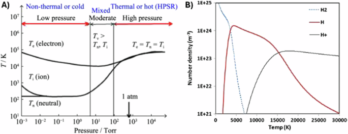
Panel A contains classifications of thermal vs. non-thermal plasmas based on temperature and gas pressure, where Te, Ti, Tn, and Tv stand for electron, ion, neutral and vibrational temperature (Reproduced from K. Sabat44), and panel B depicts the number density of species found in a hydrogen plasma at 1 atm in local thermodynamic equilibrium as a function of temperature, showing the predominance of H radicals at temperatures from 5000 K to 15,000 K. (Reproduced from K. Sabat and A. Murphy)48.
Thermodynamically, HPR makes ΔG of iron reduction more negative, which is how HPR is able to overcome the endothermic nature of reduction with H28. For example, HPR has reported rates of ~1 kg • m−2 • s−1 of oxygen removed from FeO44,45. These different ions and radicals of hydrogen possess higher enthalpies than ground-state H2, and HPM have been shown to have lower activation energies for FeO reduction than H2, with reactivity that scales as follows: H+ > H2+ > H3+ > H > H246,47,48. The ratio of these species found in the plasma is related to the temperature of the plasma, as represented for select species in Fig. 6B.
To facilitate HPR, the iron ore should be placed within the plasma arc zone because ionized hydrogen is very short-lived, but ideally the polarity of the surface should be negative to increase the reduction potential of ionized hydrogen44.
Reactor designs often rely on EAFs that can be adjusted to accommodate hydrogen plasmas. There are two common configurations in these furnaces, known as transferred and non-transferred referring to the location of the anode, which is outside or inside the plasma torch, respectively. The location impacts the overall operating conditions and performance, with the transferred mode allowing for energy efficiencies of 90%–100%, and powers of 40 MW42.
In many discussions of HPR, the reactivity of HPR is discussed in terms of Ellingham diagrams, as shown in Fig. 3, which is a fair and true comparison of monatomic H gas to H2 and other oxidation reactions. However, widely reported values for the reaction of protons and electrons in Ellingham diagrams:
are misleading because Ellingham diagrams capture thermochemical processes, but plasmas are fundamentally electro-thermochemical. The ionic repulsion and attraction of plasmas make the equilibrium constant of reactions a function of temperature, pressure, and applied electromagnetic field, which makes plotting reaction 16 as a function of exclusively temperature misleading. In addition to the high temperature, other conditions, including high pressure, would be required to match the ΔG⁰ commonly given in Ellingham diagrams, including Fig. 3. In practice, HPM reduction of iron ores does not require pressures close to the case represented on Ellingham diagrams.
While HPR is promising, many challenges still exist regarding scaling. Generally, reactor and process design must take into account the interactions between the plasma, ores, and iron product, with the plasma’s properties highly dependent on the energy and density of the gases present as well as the plasma species’ short lifetimes causing large spatial variability in many cases. Designs must incorporate extremely localized effects, such as temperature gradients at interfaces, which must be balanced with increasing the interfacial area to ensure favorable kinetics. While scale-up of HPR reactor design can be difficult43,44,48,49, there are promising leads of plasma arc furnaces used for the separation of titanium-based alloys, especially by AMG Engineering50.
Smelting with H2 could also be achieved without use of plasma. The smelting process yields a pure, slag-free molten iron. This product can be efficiently processed in EAFs and mini mills. Because the gangue is removed in the smelt reduction step, a wide variety of feedstocks can theoretically be accommodated, including U.S. taconite ores, low grade ores that were previously considered waste and discarded as tailings, and fines. Substituting hydrogen as a reducing agent in smelting furnaces is a potentially promising pathway toward green iron production from alternative ores.
As mentioned above, due to the high heating demands, smelt reduction is energy-intensive even when natural gas is utilized, requiring over 18 GJ of energy per tonne of steel produced7. Utilizing hydrogen in a typical smelting furnace presents an even greater challenge from an energy intensity standpoint, due to the endothermic nature of H2-based reduction. To reach the temperatures required by this process (upward of 1500 °C), industry generally relies on exothermic chemical reactions (generally carbothermic reactions of fossil fuels). Thus, achieving renewable process heat is a major hurdle in hydrogen smelting.
A potential alternative to fossil fuel heating is the integration of concentrating solar thermal (CST) with H2 smelting reduction (CST-H2SR), as illustrated in Fig. 7. Direct solar thermal heating could provide sufficient energy input to meet the endothermic requirements of H2-based reduction. Domestic solar irradiance is sufficient to scale this technology to match domestic ore production, and previous laboratory demonstrations of thermal energy storage (TES) systems indicate that intermittency associated with the diurnal solar cycle and cloud cover can be addressed with TES for longer operation, making the solar resource more than adequate to meet demand. Multiple experimental demonstrations, mostly in the field of solar thermochemical fuel production, have shown that temperature can be reached reliably with CST51,52,53. In addition, solar receiver technology has advanced, with commercialization efforts by companies such as Heliogen and Synhelion, demonstrating high-performance solar receivers at relevant temperatures54,55. Thanda et al. 56,57,58 have developed CST reactors for analogous processes, proving viability and identifying suitable materials and reactor geometries, but this work must be translated to iron reduction.

Hydrogen-based smelting could occur in the tower receiver, heated by concentrated solar.
In addition to hydrogen-based ore reduction, ammonia-based ore reduction has been proposed and demonstrated at lab scale59,60. Ammonia direct reduction is similar to H2DR, proceeding at temperatures above 700 °C. Liquid anhydrous ammonia has a high volumetric hydrogen content of 121 kg-H2 m−3. This is higher than the volumetric hydrogen content of H2 (70.8 kg-H2 m−3 in liquid H2 at −253 °C). Liquid anhydrous ammonia also has a higher energy density than H2 (4.25 vs 2.81 kWh L−1 of liquid hydrogen)60. Importantly, ammonia does not need to be cracked into hydrogen and nitrogen, but can be used directly to reduce iron ore to iron. While ammonia is currently synthesized via the carbon-intensive Haber-Bosch process that relies on hydrogen produced by steam methane reforming, alternative synthesis pathways are being developed that could make ammonia more attractive as a reducing agent for iron ore in the future.
Other approaches rely on electrolysis rather than chemical reduction for the production of iron. Electrolysis is an attractive option because it is fully electrified, often highly efficient, and can be optimized to accommodate a variety of ores, including low quality ores61. Furthermore, intermittent operation of electrolytic technologies is often possible, making them compatible with intermittent sources of renewable electricity.
Industrial deployment of electrochemical reduction of iron ore may draw inspiration from the electrolytic processes commonly utilized throughout metallurgical industries to produce metals including lithium, aluminum, and magnesium62. In electrolysis, instead of using a chemical compound as a reducing agent, reduction is accomplished by directly using electrons to reduce ores to metal. This is achieved in an electrochemical cell, which in its most basic configuration is composed of two electrodes in an electrolyte. Ore is generally dissolved or suspended in the electrolyte. One electrode is a cathode, where the reduction of the dissolved metal ore takes place, generating iron, and the other is an anode, where an oxidative reaction, usually formation of a species such as CO, CO2, O2, or H2O takes place.
The two electrodes are in electric contact, typically through a circuit that allows external application of a potential (voltage). The electrons removed from the oxidized species at the anode are exactly balanced by the electrons gained by the reduced species at the cathode. In this case, the species reduced at the cathode is ore. Thus, the cathodic surface area determines the rate of metal production. In the electrolyte, to maintain charge neutrality, conductive ions migrate to the electrodes and balance charges lost or gained. A schematic of a typical electrochemical cell is given in Fig. 8. Two electrolysis routes have gained significant attention. The main difference between them is the electrolyte. One uses an aqueous (water-based) electrolyte with an iron-containing solution or suspension of ore grains. The other uses a molten oxide electrolyte.
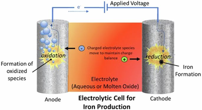
Illustration of basic operational principles of an electrochemical cell for iron production.
Aqueous electrolysis occurs at relatively low temperatures compared to other ironmaking technologies. Usually, an alkaline solution (often made with sodium hydroxide) is used as the electrolyte. The anode is made of an inert, conductive material, such as nickel. Most commonly, the cathode is also an inert, conductive material, and the ore is suspended in the electrolyte as a slurry, in which case the ore is reduced to iron when it makes contact with the surface of the cathode12,62. The reduction of ore (in the case below, hematite) occurs at the cathode by the following reaction:
The reaction that occurs at the anode, at a ratio that balances the electron flow, is:
However, under the potentials and pH typically used for iron reduction via reaction 17, the following cathodic hydrogen formation (water splitting) reaction may also occur:
Faradaic efficiency, an important metric in evaluating electrochemical reactions, is defined as the percent of the total consumed charge (total number of electrons) that went into the reaction of interest (in this case, reaction (17)) to form the desired product. Achieving high Faradaic efficiency requires suppression of reaction (19). As early as 2008, Allanore et al. 63 reported Faradaic efficiency of up to 60% for this process, which has since been further optimized.
The high efficiency and low temperature of the aqueous process make it appealing from an energy balance standpoint. Furthermore, in contrast to many other iron reduction techniques, the aqueous process could operate intermittently, which is more compatible with renewable electricity sources.
In contrast to the aqueous approach, molten iron electrolysis utilizes a molten oxide electrolyte and allows direct reduction of iron oxides into liquid metal. With the very high current densities possible with molten oxide electrolysis, industrially competitive rates of metal production can be achieved61. These cells must operate at a temperature higher than the melting point of iron (1538 °C). The liquid metal dissolves a significant amount of the ore, generating ionic species in the molten oxide and metal. The cathodic reaction of the charged iron species is:
And the anodic reaction of the oxygen component of the oxide is:
As the molten salt electrolyte, unlike water, is not easily reduced under reaction conditions, side reactions analogous to water splitting (reaction (19)) are not a concern. Molten-oxide electrolyte reduction of iron has been demonstrated with exceptionally high current density. The mechanism of this process may be compared to the Hall-Héroult process for aluminum production.
As electrochemical reactions are inherently a two-dimensional process occurring at interfaces, scaling, and reactor optimization is significant. Reactors must be engineered to mitigate mass transfer-based rate limitations. Successful strategies include maximizing the ratio of electrode surface area to electrolyte volume. For both aqueous and molten salt electrolyte-based systems, there is significant potential to process low-grade ores, but accommodation of a variety of ore types still presents many research questions. In the aqueous process, hematite is the most easily reduced oxide, and the reaction must be optimized for other iron oxides. In both cases, possible contamination due to gangue must be addressed12,62. Similar to H2DRI, electrolytic approaches produce pure iron without any carburization, which presents challenges in further processing. Finally, the molten oxide approach requires harsh operational conditions, leading to significant materials degradation challenges at the anode. For example, degradation mechanisms have been identified for even iridium anodes under operating conditions64.
The techniques discussed above all concern primary iron reduction from iron ore. However, this iron must be made into steel, and the most promising low-carbon route is steelmaking in EAFs. As an electrified process, EAF steelmaking produces substantially lower CO2 emissions than traditional steel production. Due in large part to extensive use of EAFs, steel production in the United States emits relatively less CO2 compared to global averages.
Despite the advantages of EAFs, decarbonization of the steel industry will not be achieved by increasing reliance on EAFs alone. Primary iron production is still necessary, and will continue to be necessary. This is because impurities, especially copper, accumulate in steel scrap. Certain end uses cannot tolerate these impurities. Also, production from EAF route is limited by scrap availability from the turnover of steel stocks.
Furthermore, EAFs, while cleaner than BFs, still produce significant CO2 emissions. Electrical energy accounts for only ~60% of the input energy to EAF, with the remainder dominated by reactions of carbon in the melt, the electrodes, and combustion heating (Fig. 9)65,66. The additional energy that carbon supplies serves to melt the steel charge faster than with arc heating alone (carbon oxidation to CO and CO2) and to manage Fe yield losses to the slag13. Additionally, when carbon reacts with oxygen and becomes gas, it assists nitrogen removal. The resulting foaming forms a protective slag layer that shields the refractory furnace lining from the otherwise damaging high intensity electric arc. The elevated carbon levels in the bath are adjusted (again, by selectively oxidizing the carbon in the bath to CO) to a target level before tapping, deoxidizing, optional ladle refining, and casting. Thus, even if the electricity driving EAF is from 100% carbon-free sources, carbon reactions in the EAF emit significant CO267,68.
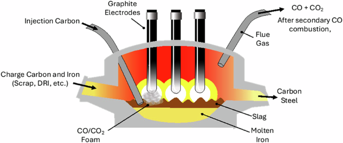
Illustration of EAF operation depicting various carbon uses.
Four distinct carbon inputs to EAFs can be identified (Fig. 9)69. (1) Charge carbon is blended with the iron-source at a loading of 2–7 kgC/tonsteel before entering the EAF for the purpose of controlling parameters such as product carbon content and melting behavior66. Conventional EAF processes utilize coal-coke or petroleum coke (e.g., pet coke) as their charge carbon. Preliminary biochar experiments have shown effective substitution of biochar as charge carbon, with the lower density of biochar offset by adding additional volume of biochar 66. (2) Injection carbon is injected into the slag or slag/iron interface using a hollow lance at a rate of 5–10 kgC/tonsteel to generate slag foaming66,70. Carbon reacts with injected oxygen, as well as FeO present in the slag, to generate CO and CO2, ultimately resulting in foaming of the slag, and additional iron reduction71. This charge carbon reaction contributes to multiple processes within the reactor, including protecting the electrodes. Coke with the desired low surface area and high density is used to control foaming rates. (3) Graphite electrodes are used for the EAF process and are slowly consumed by the process (Fig. 2), emitting 4–7 kgCO2/tsteel72. Graphite electrodes are currently made by mixing needle coke with pitch (both made from petroleum or coal) and heating the extruded forms up to 3000 °C73. (4) Combustion heating by oxy-combustion of natural gas produces emissions of 10–20 kgCO2/tsteel69,74.
The variability in the quantity of each carbon feedstock used in EAF depends on several factors including desired melt-in/tap carbon levels, initial charge chemistry, recovery of charge carbon, oxygen usage, and desired product carbon content. It is possible that, with appropriate processing, these carbon inputs could be replaced with biomass-based carbon or carbon from CO2, achieving carbon neutrality. For example, the reaction of CO2 to form graphitic carbon has been demonstrated in catalytic reactors and in molten salt-based electrochemical systems. These technologies, though relatively immature, have great promise toward achieving a circular carbon economy75,76.
A primary hurdle in deployment of biomass-based resources is ensuring feasibility of the approach from a biocarbon availability standpoint, though the billion-ton study indicates that sufficient biological resources may be available77. Conversely, processing of biocarbon sources typically results in fractionation into several product/byproduct streams, and synergistic utilization of various biomass processing byproducts could distribute costs and associated emissions across a broader base of products. Economically, Wiklund et al. 20 suggest that utilization of biomass is plausible, but further study is needed, especially on the topic of biomass drying, which has a substantial impact on energy consumption.
A number of challenges also involve the inhomogeneous nature of biocarbon. For example, biochar is a diverse product with a range of possible ash/gangue contents, and the acceptable subset of biochar feedstocks compatible with EAF is not understood. As a specific example, prior testing of biochar as injection carbon resulted in feeding issues, due to lower density of biochar, high friability (e.g., fragility), and higher rates of decomposition prior to making contact with the slag/iron compared to coke78. However, investigations of biocarbon processing targeting production of denser biocarbon tailored to use as injection carbon are ongoing.
The viability of biocarbon utilization will depend greatly on chemical processing. For example, the graphite electrodes used in EAFs are currently made from needle coke and pitch sourced exclusively from petroleum residue or coal tars. Replacing them with renewable sources could reduce GHG emissions, but would require engineering of specific morphologies and properties to result in electrodes with the desired conductivities and rates of consumption.
Ultimately, many of the processes presented here rely on electrification, whether to produce hydrogen via electrolysis, provide energy for plasma, provide a driving force for electrolysis, or to process biomass. Many of the processes are still energy-intensive. For example, while the H2DRI method may still require upward of 14 GJ of energy per ton steel, over 90% of the energy could come from electricity, whereas the BF process requires mostly fossil fuel (coal) energy79. Ultimately, electrified processes have the possibility of being carbon neutral, but are only as clean as the electricity generation method. Thus, development and integration with renewable energy resources is imperative for the progress of iron and steel decarbonization.
As an additional consideration, electrification of energy-intensive industries presents possible cost increases and feasibility problems from the standpoint of the electrical grid, and off-grid solutions may need to be considered. Modeling has demonstrated that electrification of production of steel, cement, glass, lime, petrochemicals, chlorine, and ammonia alone would require over 1.5 times the total electric capacity of today’s grid59. Electrification of vehicles and other sectors is already expected to cause grid reliability problems. These factors, together with the technical difficulty of electrified high temperature reduction with H2, make off-grid decarbonization solutions appealing.
Work is currently underway to identify optimized locations and scenarios for integration with renewables. Analysis includes grid-connected and off-grid scenarios. The geographic availability of resources is key. Also, energy storage, especially in the form of hydrogen storage, is considered, as energy storage could help solve intermittency issues associated with renewable energy. This work must progress alongside efforts to accelerate the development of iron and steelmaking technologies themselves in order to truly achieve decarbonized solutions.
Ultimately, there are many promising approaches to iron and steel decarbonization, but key challenges must be overcome to move forward. H2DR could integrate with existing DR infrastructure, offering perhaps the most straightforward path to deployment. Hydrogen is an excellent reducing agent and is in fact a part of the reducing gas blend utilized in current DRI furnaces. Pilot demonstrations are already underway. However, challenges remain; as the endothermic reaction requires new thermal management solutions, feedstock options may be limited to high-grade ores, and the properties of H2DRI are not ideal for contemporary processing in that they crack easily and are not carburized.
HPR relies on generation of a hydrogen plasma, which could be accomplished in an EAF. While this approach also relies on reduction with hydrogen, many of the thermal management issues are solved, as the localized temperature is extremely high and the hydrogen plasma is substantially more reducing than hydrogen itself. However, in order to achieve cost-effective deployment, significant technological hurdles must be overcome, including scaling and reduction of energy intensity.
Hydrogen smelting is a possible route to produce gangue-free, liquid iron. The requisite high temperatures could be generated with solar thermal, which has been demonstrated to be feasible in related applications. However, reactor design, materials compatibility, and intermittency issues must be solved for deployment of this approach.
Electrolytic iron reduction utilizes electrons to directly reduce iron species. There are two common approaches, one utilizing an aqueous electrolyte and the other using a molten oxide electrolyte. Aqueous systems could be operated intermittently, integrating well with renewable energy resources, and both processes could be optimized to accommodate a variety of ores. However, scale-up, materials degradation problems, and accommodation of low-grade ores remain challenging hurdles. For molten oxide electrolysis, high energy consumption is also a problem.
Biocarbon or carbon from CO2 could be used in EAFs to replace the fossil fuel-based carbon that is currently required. EAF-based scrap recycling is a significant fraction of steel production, and that fraction is likely to grow13. Furthermore, EAFs will likely be used to process H2DRI and iron reduced by aqueous electrochemistry, so it is important to decarbonize their operation in tandem with deployment of green iron production routes. Challenges such as biocarbon processing and availability remain. Technologies to convert CO2 into useable carbon are still in their infancy. However, both biomass and CO2 utilization provide potentially promising routes to fully decarbonized EAF operation.
Finally, it is important to note that all approaches rely on successful integration with renewable energy resources. Continued development of green hydrogen and renewable electricity infrastructure is essential to the decarbonization of iron and steel.

Responses