Agile robotic fish based on direct drive of continuum body

Introduction
Underwater robots have significant utility for tasks in aquatic environments, including artifact inspection, ecology investigation, resource exploration, and rescue operations. Biomimetic underwater robots that ingeniously incorporate biological structures and functionalities offer the potential to achieve high mobility and efficiency similar to aquatic organisms1,2,3,4. Furthermore, traditional propeller-equipped underwater robots have faced challenges related to the entanglement of marine life and environmental disruption caused by strong water currents, highlighting environmental concerns. Accordingly, biomimetic robots, which are based on biological emulation, have been actively pursued as a solution to address these issues1,2,3,4. Underwater robots based on the biomimetic approach are paving the way for advanced underwater systems capable of a wide range of tasks in various liquid environments.
Many robots inspired by various aquatic organisms1,2,3,4,5, such as fish6,7,8,9,10,11, eel12,13,14, ray15,16,17, and jellyfish18,19,20, have been developed. These robots may be broadly classified as being based on two approaches depending on their architecture. One is the so-called rigid robotic approach, in which electromagnetic motors or servos and their associated rigid transmission components form the active moving body to generate swimming motions2,3,4. The other is the soft robotic approach, in which a soft actuator that deforms itself, such as electroactive polymers6,14,15,18,21 and fluid-driven soft actuators9,13,20, forms a portion of or the entire body and directly moves it1,5. The advantages of the rigid robotic approach are associated with the features of motors, such as ease of integration, high energy density, efficiency, positioning accuracy, and frequency response. However, the presence of a transmission mechanism including gears, cranks, sliders, hinges, linkages, and wires introduces complexities in the robotic structure. This makes the robots susceptible to damage from severe impacts, potentially compromising mechanical robustness1,22. Although the motors themselves are highly efficient, energy losses in the transmission mechanism and its weight would reduce the resulting efficiency and specific output23. Meanwhile, the soft robotic approach has the advantage that the actuator can achieve a type of automatically generated swimming motion because of the interaction between the continuous, simple, and flexible body and the surrounding water. This implies that the control input can also be simplified, resulting in a simple on-off in extreme cases. In addition, the softness contributes to improving the mechanical robustness of the structure. However, in many cases, individual soft-actuator technologies present one or more of the following challenges: low response speed, low efficiency and energy density, and small deformation and force output.
In this study, we hypothesize that when both rigid and soft robotic approaches are combined, that is, when a robot has a flexible continuum body directly driven by a motor, the simplified high-energy-density structure and its interaction with the surrounding water provide the robot with high-performance swimming capability. As a specific way to verify this hypothesis, we propose direct-drive (DD) as an actuation method for motor-driven biomimetic underwater robots. As the name implies, DD moves the robotic body directly, eliminating the need for transmission parts. This results in the expected improvement in the output performance and mechanical robustness of the robots. Moreover, DD enables the motor to directly interact with the surrounding water through the body. Because of this functionality, we expect DD to also be capable of simplifying the complex control often required for traditional motor-driven underwater robots. This is analogous to the simplification of control through the passive deformation of the structure, which is well-known in the soft robotic approach. In the literature, DD has demonstrated validity in legged terrestrial robots23; however, to the best of our knowledge, no case of implementation in biomimetic underwater robots has been reported. In this context, the focus of the present study is to investigate the swimming characteristics that can be achieved by the DD approach through the characterization of a robotic fish platform.
Results
The robot developed in this study has a morphology inspired by the anatomy of Carangiform swimmers (Fig. 1a)24, measuring a total length (head-to-tail) of 412.5 mm and weighing 1.1 kg (see Supplementary Fig. 1 for the detailed dimensions). It mainly comprises a head, motor, flexible body, and tail fin (Fig. 1b). The head part accommodates drive control components such as a set of batteries, receiver, microcontroller, and motor driver. To simplify the experimental design, the primary mode of robot swimming is set as forward. Therefore, the components required to achieve multi-degree-of-freedom motion, such as pectoral fins, are absent. The control system embedded in the head part allows the generation of driving signals to the motor with different waveforms of input current as a function of time. In this study, we employ two waveforms: square and sine waves (see also Supplementary Note 1). Square waves are frequently used in soft underwater robots6,13,14,15, and sine waves are typically used in rigid underwater robots10,25,26,27. This is because soft robots exploit passive structural deformation to reproduce fish-like undulating motions, while in rigid robots such motions are realized by transmission mechanisms in which the input and output are mechanically matched. To reveal the swimming characteristics derived from the DD method, which combines rigid and soft robotic approaches, it is important to use both square and sine waves for driving the robot.

a Developed robot designed with a streamlined shape resembling a real fish to minimize fluid resistance. b Schematics illustrating the components in the robot. A brushless DC motor equipped with an encoder is directly connected to a flexible body and tail fin. The motor is also connected to a head part, in which control and communication modules are placed (see Supplementary Information for more detail). c High backdrivability and simplified structure facilitated by the DD architecture enable the robot to withstand external impacts (in this case, hitting by a hammer; see also Supplementary Movie 1). d Swimming motion of the robot at a driving frequency of 2 Hz (see also Supplementary Movie 5).
A high-torque, high-energy-density brushless DC motor (U8II Lite 100KV, T-MOTOR) is employed, which directly moves the flexible body followed by a tail fin. The DD method aligns well with brushless DC motors—known for their high torque and responsive frequency characteristics (e.g., ability to produce an amplitude of 360° at 20 Hz24)—rendering them suitable for our DD method, which achieves high-power, high-speed swimming. Moreover, this type of motor, being devoid of rotor-stator contact, requires minimal waterproofing treatment, further contributing to structural simplicity. The motor used in this study weighs 242 g and constitutes 21.6% of the total weight of the robot. This aligns closely with the biological observation that fish muscles account for ~20% of their total body mass28.
The flexible body is made of silicone rubber encapsulating a thin sheet of carbon fiber reinforced polymer (CFRP) by a molding process (Supplementary Fig. 2). Forming the body as a flexible continuum ensures simplicity, flexibility, mechanical robustness to external impacts, and durability to deal with operation in a wide frequency range. The tail fin, designed with an aspect ratio of 3.5 employed on the basis of preliminary experiments (see Supplementary Note 3 for more detail), is made from the same thin CFRP sheet. The reason behind using CFRP is to exploit the resonance modes in the relatively high-frequency domain. Researchers have demonstrated that efficient swimming emerges with natural vibration modes and that agile locomotion can be achieved at high frequencies6,8,11,29,30,31. We designed the body and tail fin to have the first and second resonance modes within the tail beat frequency range of up to ~20 Hz according to a previously reported analytical approach32. In particular, from the designing result, we expected the first and second natural frequencies as 3.3 Hz (({f}_{w1})) and 21.9 (({f}_{w2})) Hz, respectively, in the case where the robot was fixed in the experiments (discussed later), and as 1.8 Hz (({f}_{w1}^{{prime} })) and 11.6 Hz (({f}_{w2}^{{prime} })), respectively, in free swimming (see Supplementary Note 5 for more details).
With the aid of DD and the flexible continuum body, the fish robot has a high backdrivability that provides high mechanical robustness; it can dissipate external impacts without causing any mechanical failures even when hit by a hammer (Fig. 1c, see also Supplementary Movie 1). This feature is often difficult to realize with traditional motor-driven fish robots that have low backdrivability and a body consisting of several transmission parts and structural components, which face the risk of damage upon impact.
The robot achieved fish-like motion and subsequent swimming locomotion by oscillating the brushless DC motor with a given operating angle, which in turn generated thrust through the passive deformation of the flexible body and tail fin (Fig. 1d). The experimental setup used for this observation is shown in Fig. 2e. In the robot, the angular command to the motor, i.e., the swing angle of the body, was set as ±30° for all experiments except for the measurement of turning speed (described later) according to the preliminary test (Supplementary Note 4). A previous study reported ±30° (swing angle of 60°) as an optimal value for a servomotor-driven fish robot26, which motivated us to use the same value. The robot sends an angular command to the driver, which then generates the motor’s input using a proportional derivative (PD) control scheme. The PD gains were determined through a preliminary test, which was conducted at a driving frequency of 10 Hz (see Supplementary Note 2 for more detail). For the sake of simplifying the experiments, these gains were fixed for all tests. Therefore, it should be noted that they may have more optimal values at frequencies other than 10 Hz.
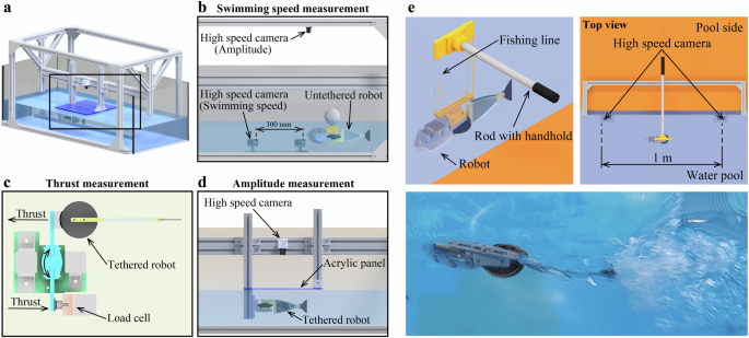
a Experimental setup using a water tank (750 × 600 × 1800 mm (W × H × L)). In this setup, b swimming speed in the low-frequency domain (0–5 Hz, a float is placed on the robot), c thrust force, and d tail amplitude as well as turning speed are measured (see Methods for more details). e Experimental setup used for measurement in a pool. The robot without a float is suspended on a rod using a fishing line, and the swimming speed in the high-frequency domain (7.5–20 Hz) is measured. The bottom-right image shows a picture taken during the experiment (see also Supplementary Movie 2). During the experiment, a conductor holding the rod runs along the pool while following the swimming speed of the robot. Two synchronized waterproof video cameras placed at the side wall of the pool measure the speed of the robot passing in front (see Methods for more details). Because the position of the conductor (i.e., the tip of the rod) is slightly behind the robot, the swimming speed can decrease but cannot increase.
The nature of the robot to directly drive the flexible structure suggests that the resonance oscillation of the continuum body contributes to the swimming performance. In the tested tail beat frequency range of 7.5–20 Hz, the measured swimming speed of the robot reached a peak of 2.6 m/s at 10 Hz, corresponding to 6.3 body length (BL)/s (Fig. 3a, Supplementary Movie 2) with square waves. In the case of sine waves, the swimming speed reached 2.4 m/s (5.8 BL/s) at 12.5 Hz. Figure 2e presents the experimental setup used for this measurement. The peaks for the square and sine waves appeared at 10 and 12.5 Hz, respectively, which were around the second natural frequency of ({f}_{w2}^{{prime} }=11.6) Hz predicted by the model, indicating the presence of a resonance likely to be the second mode.
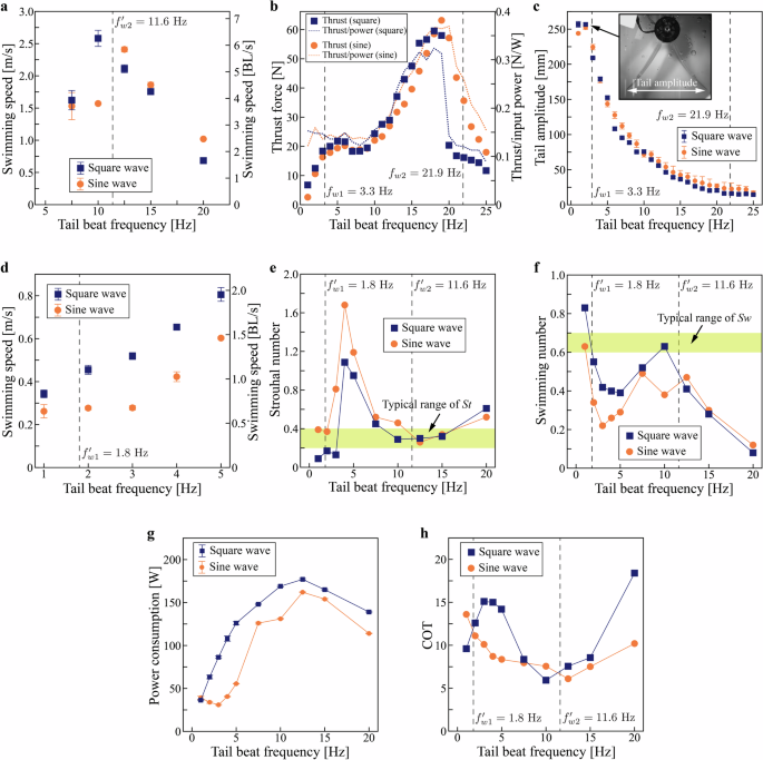
a Swimming speed in the high-frequency domain and corresponding body length (BL) per second. The speed reaches 6.3 BL/s (2.6 m/s) at 10 Hz (see also Supplementary Movie 2). b Thrust force and thrust/input power (specific thrust). In the specific thrust, peaks are observed around 2 and 19 Hz, suggesting efficient swimming. c Tail amplitude (sine wave, see also Supplementary Movie 3). It decreases with an increase in the frequency owing to damping caused by the surrounding water. d Swimming speed in the range of 0–5 Hz and corresponding BL/s (see also Supplementary Movie 5). The speed increases with the increase in frequency. e Strouhal number. Around the predicted frequencies (({f}_{w1}^{{prime} }=1.8) Hz, ({f}_{w2}^{{prime} }=11.6) Hz), the Strouhal number lies within the typical range observed in nature (0.2–0.4). f Swimming number. Data show a similar trend to that of the Strouhal number. g Power consumption. It reaches the highest value at 12.5 Hz. h Cost of transport (COT). The minimum value observed is 5.9 at 10 Hz. The error bars on the data points in each subfigure indicate the standard deviation.
This was further supported by the data of thrust force of the robot measured in a fixed condition (Fig. 2c). The thrust force increased with the increase in the tail beat frequency and reached a peak value of 63.2 N at 19 Hz (corresponding to a specific thrust of 0.36 N/W) for sine waves and 59.2 N at 18 Hz (0.32 N/W) for square waves (Fig. 3b). When considering the specific thrust (thrust/input power), peaks were observed around 2 and 19 Hz, suggesting efficient swimming and the presence of resonance modes. These peaks appeared near the predicted values of the body natural frequency (({f}_{w1}=3.3) Hz, ({f}_{w2}) = 21.9 Hz). See Supplementary Movie 3 for the body deformations at 2 and 19 Hz.
We expected to observe the peaks when measuring the tail amplitude of the robot in a fixed condition (Fig. 2d). However, after reaching an amplitude of 256.7 mm at 2 Hz, it gradually decreased with the increase in the tail beat frequency without any indication of other significant peaks (Fig. 3c). This suggests that the damping of the structure by the surrounding water is dominant, implying that even if resonance modes appear, they are not immediately apparent in amplitude. This is further confirmed by the results of a comparison of tail amplitude in air and water (Supplementary Note 6).
The high response speed and backdrivability along with a wide range of operating angles of the robot owing to the DD method also enable rapid pivot turning, which is described as an escape maneuver33. The experimental result, obtained using a setup similar to the one illustrated in Fig. 2d, reveals that the robot achieved a turn of ~90° within 110 ms from an initial static state, with a maximum angular speed of 1450°/s (Fig. 4). See Supplementary Movie 4 for the movement of the robot. Note that the robot would turn in the opposite direction when the tail swing back to the original position. Thus, asymmetry in the tail motion between the turning stroke and the recovery stroke needs to be considered in actual turning maneuvers.
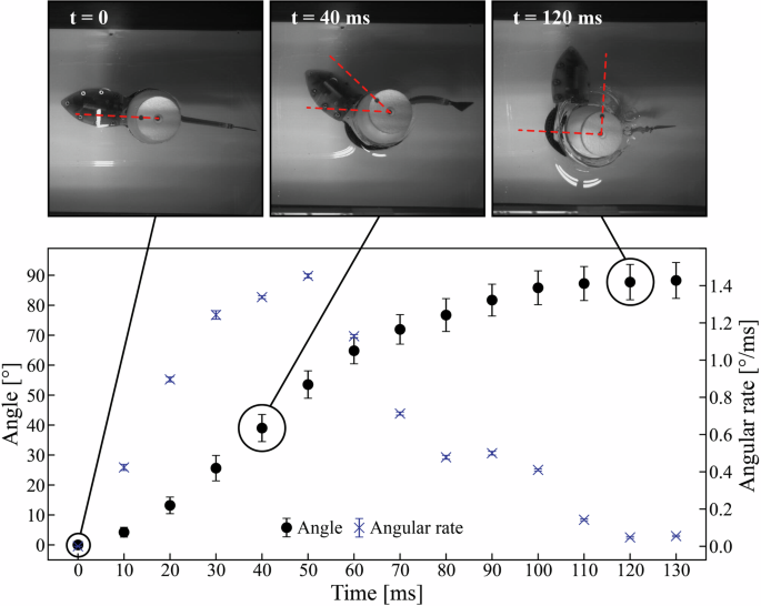
Data are presented as angle and angular rate as functions of time (see also Supplementary Movie 4). The robot achives a turn of approximately 90° within 110 ms from an initial static state, resulting in an angular rate of 1450°/s. The error bars on the data points indicate the standard deviation.
As mentioned previously, the measured specific thrust (Fig. 3b) indicates efficient swimming around 2 and 19 Hz. This is probably consistent with the fact that aquatic organisms such as fish swim efficiently in steady-state swimming24,28,34. The Strouhal and swimming numbers are quantitative expressions of stead-state fish swimming. In the literature, it has been observed that the Strouhal and swimming numbers of real fish typically converge within the range of 0.2–0.4 and 0.6–0.7, respectively24,28,34. The Strouhal number is defined as ({St}={fA}/U), where (f) is the drive frequency, (A) is the peak-to-peak amplitude distance of the tail, and (U) is the swimming speed. Further, the swimming number is defined as ({Sw}=U/{fL}), where (L) is the fish body length. By measuring the swimming speed (Fig. 3a, d, Supplementary Movie 5) and tail amplitude, we calculated the ({St}) and ({Sw}) of the robot for the tail beat frequency range of 0–20 Hz. Above 3 Hz, ({St}) was calculated as a quasi-value using the amplitude data shown in Fig. 3c. The reason for this is that above 3 Hz, it was difficult to accurately observe the amplitude in free swimming owing to distortion caused by waves on the water surface. The results plotted in Fig. 3e, f show that ({St}) and ({Sw}) fall within their typical range observed in nature around the frequency values predicted by the model (({f}_{w1}^{{prime} }=1.8) Hz, ({f}_{w2}^{{prime} }=11.6) Hz). These results imply that the swimming behavior of the robot closely approximates that observed in real fish, illustrating a functionality in addition to the rapid motions.
Next, we investigated the swimming behavior of the robot from an energy efficiency perspective by considering the cost of transport (COT). COT represents the energy consumed to travel a unit distance and is defined as ({rm{COT}}=P/{mgU}), where (P) is the average power consumption (Fig. 3g), (m) is the mass, (g) denotes the gravitational acceleration, and (U) is the swimming speed. The COT reached a minimum value of 5.9 at 10 Hz for square waves and 6.1 at 12.5 Hz for sine waves (Fig. 3h). The COT values of the square and sine waves reached minima around the predicted frequency (({f}_{w2}^{{prime} }=11.6) Hz). In the case of square waves, the COT also decreased toward the model prediction (({f}_{w1}^{{prime} }=1.8) Hz). The low COT values obtained in this study suggest the effect of the DD method, where elastic energy is stored by the body under resonance modes, which reduces the load on the motor and thereby the power consumption, resulting in more efficient swimming. A comparison of the COT generated from square and sine waves revealed that the latter exhibited an overall lower trend. This indicates that sine waves are suitable for efficient swimming and square waves for agile movements. One possible reason is that sine waves excite shape deformation more smoothly, resulting in motions with less fluid resistance, whereas the opposite is true for square waves.
Discussion
The simplicity of the fundamental architecture of the robot, that is, the brushless DC motor directly connected to the passive, flexible continuum body, ensures transmission of the power of the motor to the body and tail fin as well as assures mechanical robustness under external impacts. The observed rapid swimming of the fish robot, 6.3 BL/s (2.6 m/s) in the forward direction and 1450°/s in turning (110 ms to achieve a 90° pivot turn from a static position), is rarely achieved within a single system. The swimming speed of the robot compares well with that of real fish (Fig. 5, data adopted and replotted from refs. 8,35), illustrating its high performance comparable with its natural counterpart. Notably, there is a study on a geared motor-based fish robot in which speed is reported as 11.6 BL/s36. However, this work is not plotted in Fig. 5, as the original dataset from refs. 8,35 not include it. Additionally, the ref. 36 does not show any visual data that allows readers to objectively determine or estimate the speed, such as a sequence of swimming or a video of locomotion. The turning speed of our robot is more than four times higher than that of a fish robot capable of escape maneuvers33. At a speed of 6.3 BL/s observed at the tail beat frequency of 10 Hz, a minimum COT of 5.9 is achieved owing to the resonance mode of the body, which directly interacted with the surrounding water and facilitated elastic energy storage. Around this frequency (~10 Hz), the Strouhal and swimming numbers fall within the typical range observed for real fish. Both numbers reach the typical range at a low frequency as well (~1 Hz). These results suggest that the robot achieved swimming characteristics similar to those of real fish. The two frequency domains (~1 and ~10 Hz), where rapid and efficient swimming is achieved, are similar to the resonant frequency predicted by the model (({f}_{w1}^{{prime} }=1.8) Hz, ({f}_{w2}^{{prime} }=11.6) Hz). This implies that robots based on the DD method can be designed to a given performance specification. These outcomes validate the successful implementation of the DD method derived from the conceived concept that combines the rigid and soft robotic approaches and that the proposed DD method can be employed as a framework for biomimetic underwater robotic systems.
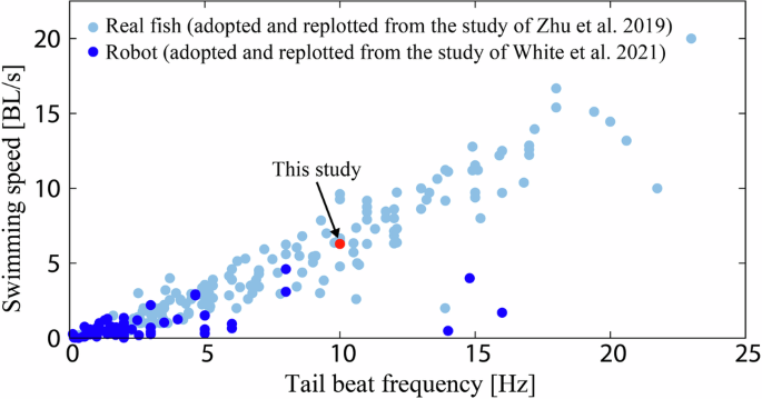
The speed of the robot developed in this study compares well with that of real fish. The data of real fish are adopted and replotted from the study of Zhu et al. 8. The data of the robot are adopted and replotted from the study of White et al. 35.
From an energetics viewpoint, the efficiency of the robot (COT of 5.9) is on the same or higher order of magnitude as that of robots in other studies (0.415, 2.88, 1.935, and 1.726), further away from real fish, indicating room for improvement. Here, the flexibility (i.e., bending stiffness) of the body and tail fin is a crucial factor. More specifically, it is reported that the bending stiffness distribution plays a critical role in maximizing thrust force and efficiency37. As stiffness is determined by the dimensions of the body and tail as well as their modulus, modifications to the shape of the body and tail fin and their elasticity will contribute to increasing efficiency. Moreover, hypotheses suggest that fish actively control muscle contractions while swimming to regulate body stiffness. For instance, tuna adjusts the stiffness of its tail for high-speed and steady-state swimming, and this mechanism has been successfully implemented in a robotic fish25. Incorporating such variable stiffness into our robot may further improve its swimming performance by modulating the frequency response characteristics. The DD method also requires investigation and establishment of robotic architecture and a control method for multi-degree-of-freedom motion because the primary locomotion of the robot presented herein is forward movement. Swimming with multi-degree-of-freedom motion can be achieved by introducing pectoral fins and a buoyancy control unit as reported in a previous study9.
In terms of the aforementioned performance improvements, computational fluid dynamics simulation that accounts for fluid-structure interaction will be a highly powerful tool. Furthermore, such simulation environments enable us to clarify, both theoretically and quantitatively, how and to what extent direct drive of the continuum body improves the swimming performance of robots compared to other methods. In parallel, the impact of the DD method on robot control and dynamics could be clarified. These endeavors also provide further insight into the fact, discovered through experimental validation in this study, that direct drive of the continuum body achieves agile movements in fish robots, moving beyond merely qualitative interpretation.
When considering the environment in which the robot performs its tasks, protection of the motor plays a particularly important role. As mentioned in the previous section, the brushless DC motor used in this study required almost no waterproofing. However, this may only be valid in tap water; seawater, which many robots often come in contact with in actual tasks, can corrode motor parts and eventually cause them to fail. To address this issue, an additional structure would need to be placed around the motor such that it does not inhibit its rotation and movement of the flexible body while providing physical insulation from the surrounding water, such as a compliant bag filled with insulating oil.
The agility of the developed robot provides the opportunity for implementing advanced functionalities. A typical example is gliding in the air after taking off from underwater, the same functionality as that of flying fish38. Flying fish are known to glide over water surfaces to evade predators and facilitate movement. They exhibit high swimming speeds exceeding 10–20 m/s at tail beat frequencies of 20–40 Hz38,39,40. To achieve swimming speeds similar to those of flying fish, an actuator with a power density of 4150 W/kg is necessary39. The brushless DC motor used in this study consumed a maximum power of 1450 W41, resulting in a power density of 5992 W/kg. This exceeds the reported values and provides high feasibility from the viewpoint of power density. Further, the robot exhibited a swimming speed of 6.3 BL/s, clearly lower than that of flying fishes. Although the brushless DC motor used in this study allows a driving voltage of up to 48 V, for safety reasons all the experiments described herein were conducted at a voltage of 25.2 V. Thus, there remains room for dramatically increasing the swimming speed even with the current robot, and the same is true for its potential as a gliding platform. We believe that by including systems with such advanced features, the proposed DD method will contribute to the creation of highly versatile biomimetic underwater robots.
Methods
Measurements in the water tank
In a water tank having dimensions of 1800 × 750 × 600 mm (L × W × H) and filled with tap water, the thrust force, tail amplitude, forward speed in the low-frequency domain (0–5 Hz), and turning speed were measured. Aluminum frames were placed around the water tank to provide structural support for measurement equipment (Fig. 2a). The driving voltage for the robot was maintained at 25.2 V for all the experiments. In the measurement of the thrust and tail amplitude, an external microcontroller board (DEV-14483, SparkFun), a motor driver (FSESC 7550, Flipsky), and a power supply (PWR801ML, Kikusui) were used to drive the robot body. The brushless DC motor equipped with an encoder (AS5047D-TS_EK_AB, ams OSRAM) was connected to the driver, and the microcontroller board controlled the motor’s position by providing angle commands to the driver, thus driving the robot.
Thrust force measurement
In the thrust force measurement, a waterproof load cell with a capacity of 445 N (LSB210, FUTEK) was used as a force sensor. The measurement setup involved attaching the robot to a lever mechanism that indirectly pushed the force sensor (Fig. 2a–i)42. When the robot generated a thrust, the lever attached to the robot rotated around an axis, pressing the other lever against the force sensor. The output signal of the load cell was recorded using a digital multimeter (2100/100, Keithley) controlled by PyVISA and saved on a PC. The sampling rate was set at 100 Hz. To account for the sensor’s initial output voltage when the robot was not driven, a 2-s baseline data recording was conducted without robot propulsion, and the average voltage was taken as the reference. The robot was then driven for 5 s, and the sensor output was recorded. The average of the recorded sensor output over 1.5 s was calculated and used as the thrust force value at the respective frequency. The driving frequency applied to the robot ranged from 0 to 25 Hz with 1-Hz increments, and the angular command to the motor was set at ±30°.
Tail amplitude measurement
In the tail amplitude measurement, above the underwater robot, an acrylic plate was placed and fixed at the water surface level to remove waves that could distort the images taken from above. In this setup, the robot was driven for 3 s, and its behavior was recorded using a high-speed camera (INFINICAM, Photron) positioned directly above it (Fig. 2a-ii). The frame rate for this camera was set at 1000 fps. The recorded video data were analyzed using image-processing software (Photron Fastcam Analysis, Photron Fastcam Viewer, Photron) to track the coordinates of the tip of the tail fin. The peak-to-peak distance of these coordinate data was recorded as the amplitude value. The driving frequency of the robot ranged from 0 to 25 Hz with 1-Hz increments, and the angular command to the motor was set at ±30°. The results were reported as the average of three measurements at each frequency.
Low-frequency swimming speed measurement
In the low-frequency swimming speed measurement, the wireless-enabled robot was allowed to swim inside the water tank, and its movement was recorded using two synchronized high-speed video cameras (Hero10 Black, GoPro) with a frame rate of 240 fps. A styrofoam ball of 100-mm diameter was attached to the robot to ensure buoyancy and stability. The cameras were positioned outside the tank, fixed to the aluminum frame to maintain a lens separation distance of 0.3 m (Fig. 2a-iii). The time taken by the robot to traverse both cameras was measured from the recorded video and used to calculate the swimming speed. The initial state of the robot was at one end of the tank, and the first camera was placed ~1.2 m from that position. Additionally, the tail amplitude during swimming was recorded using a high-speed camera (INFINICAM, Photron) fixed to the top of the water tank. Image-processing software (Photron Fastcam Viewer, Photron) was used to track the coordinates of the tail fin’s tip from the recorded video and calculate the peak-to-peak distance, which was then recorded as the tail amplitude. The driving frequency of the robot ranged from 0 to 5 Hz with 1-Hz increments, and the angular command to the motor was set at ±30°. The results were reported as the average of three measurements at each frequency.
Turning speed measurement
In the turning speed measurement, the motion of the robot, i.e., turning in clockwise direction from a stationary position, was captured using a high-speed camera (INFINICAM, Photron) fixed to the top of the water tank. The frame rate for this camera was set at 1000 fps. After the rotation, image-processing software (Photron Fastcam Analysis, Photron) tracked two markers attached to the robot’s float, a styrofoam ball with a diameter of 100 mm, and used the change in angle of the vector these markers formed to calculate the rotation speed. The angular command to the motor was set at 90°. The experimental setup used in this measurement was the same as the one presented in Fig. 2a-ii, except that the robot was not fixed. The results were reported as the average of three measurements.
Measurement in the swimming pool
In a 25-m-long swimming pool, the forward speed in the high-frequency domain (5–20 Hz) was measured. In preliminary tests, a difficulty was encountered, wherein the float attached to the robot for buoyancy and stabilization purposes created significant fluid resistance and disturbed swimming in unexpected directions. Moreover, the fast movements of the robot did not permit the use of water tanks or water tunnels because of their limited size or achievable fluid speed. Therefore, the measurement was performed by suspending and balancing the robot with fishing lines through a rod without attaching a float (Fig. 2e). Meanwhile, a conductor from the experiment, holding the rod, ran along the pool, matching the robotic swimming speed. Because the position of the conductor (i.e., the tip of the rod) was slightly behind the robot, the swimming speed could decrease but never increase. This method, measurement of swimming speed while suspending the robot, has also been used in other studies8,10,25,35. In this measurement, two synchronized waterproof high-speed cameras with a frame rate of 240 fps (Hero10 Black, GoPro) were fixed to an aluminum frame with a lens separation distance of 1.0 m. These cameras were positioned underwater to capture the swimming motion of the robot (Fig. 2e). The time taken by the robot to traverse the center line of both cameras was measured from the recorded video and used to calculate the swimming speed. The driving frequency of the robot was set at 7.5, 10, 12.5, 15, and 20 Hz, and the angular command to the motor was set at ±30°. The results were reported as the average of three measurements at each frequency.
Structure and components of the fish robot
The robot was controlled by an onboard microcontroller board (DEV-14483, SparkFun). The commands to the robot were sent using a 27-MHz-band R/C transmitter (RP-101, Sanwa). The commands were received by a receiver (RX-101, Sanwa) and then sent to the microcontroller board, which sent position commands to the brushless DC motor driver (FSESC6.7, Flipsky). A schematic diagram of the control system of the robot is shown in Supplementary Fig. 4. The robot swam at a given driving frequency for the specified duration. It was powered by a six-cell lithium-polymer battery with a maximum charged voltage of 25.2 V (6S 1050 mAh LiPo-Battery, Sunpadow), allowing ~9 min of swimming at the maximum power consumption. The power consumption of the robot during swimming was recorded using an onboard logger (DEV-13712, SparkFun).
The body of the robot was designed to be both flexible and durable for high-frequency operation by encapsulating a thin CFRP plate in a 10-mm-thick silicone structure via a molding process. After investigating the impact of stiffness differences of the CFRP on swimming in preliminary tests, a thickness of 1 mm was selected. Dragon Skin 30 (Smooth-On) was used for the silicone structure, which was poured in a mold and cured in an oven at 60 °C for more than 6 h (Supplementary Fig. 2). The mold was made of an ultraviolet (UV)-curable resin (Clear Resin v4, Formlabs) and printed by a three-dimensional (3D) printer (Form 3, Formlabs). The tail fin was crafted by cutting a 1-mm-thick CFRP plate. The aspect ratio of the fin was determined as 3.5 from preliminary tests. The fin was connected to the body using a 3D-printed part made of the UV-curable resin.
The head was made of the UV-curable resin and comprised top and bottom parts that were fixed by screws. To ensure a waterproof head, a molded gasket made of silicone rubber (Dragon Skin 30, Smooth-On) was inserted between the top and bottom parts (Supplementary Fig. 3). Water infiltration through the screw holes in the head parts was prevented by using sealing washers during screw fastening.

Responses