Advanced electrode processing for lithium-ion battery manufacturing

Introduction
Lithium-ion battery (LIB) demand and capacity are estimated to grow to more than 2,500 GWh by the end of 2030 (ref. 1). Most of this capacity will be applied to electric vehicles (>142 million electric vehicles by 2030 (refs. 1,2,3)). To ensure the supply of LIBs at speed and scale, LIB manufacturing needs to be further streamlined with higher throughput and lower cost, energy consumption and scrap rates. An important step in LIB manufacturing is the processing of electrode materials into electrodes, before cell assembly. This step impacts the manufacturing cost and throughput as well as cell performance4.
Wet electrode processing is the conventional electrode manufacturing process, and involves mixing and dispersing electrode components (such as the active material, binder and conductive additive) in a slurry, followed by the casting and drying of the slurry and calendering5. Wet processing is broadly used in industrial electrode manufacturing but is associated with high energy consumption, high manufacturing costs and limited cell performance6,7. Altogether, slurry mixing, drying (including solvent recovery) and calendering account for ~32.7% of the manufacturing costs and ~51.9% of the energy consumed in LIB manufacturing8. Owing to the high boiling points and specific heat capacity of the solvents used (water or N-methylpyrrolidone (NMP)), drying is both energy-intensive and time-consuming9 (up to a few minutes). Moreover, NMP toxicity requires complex solvent recovery operations9 and can result in leakage10.
Furthermore, when aiming to build high-energy LIBs, the mass loading of electrodes is usually increased so that the mass ratio of inactive components (for example, the current collector or separator) is reduced. However, electrode processing of high mass-loading electrodes requires a slower drying process to alleviate binder migration and uneven distribution of electrode component materials. Otherwise, electrodes exhibit poor mechanical strength, cracking and poor rate capability11,12.
Advanced electrode processing technologies, such as advanced aqueous processing13,14, dry processing15, radiation curing processing16 and 3D-printing processing17, are being developed to address these manufacturing bottlenecks (Fig. 1). Dry processing has already been commercialized, whereas the other three processes have been demonstrated at laboratory scale18. These processes provide alternatives to the conventional method, and could fulfil the requirements of scalability, facileness and rapidness, and the affordability of manufacturing high-performance LIBs18.

Electrode processing techniques usually comprise three main steps: mixing (panels 1), electrode fabrication (panels 2) and calendering (panels 3). a, Conventional slurry-based processing. b, Dry processing. c, Radiation curing processing. d, 3D-printing processing.
In this Review, we discuss advanced electrode processing techniques and compare them with conventional slurry-based processing. We review four electrode processing methods — advanced aqueous processing, dry processing, radiation curing processing and 3D-printing processing — and discuss the development and engineering of each approach, outlining operation and instrumentation aspects. Within 3D-printing processing methods, we discuss direct ink writing, material jetting, fused deposition modelling and other techniques. Finally, to promote the development and commercialization of advanced electrode processing methods, we outline our perspective on the road to market that lies ahead for 3D-printed electrodes.
Slurry-based electrode processing
Slurry-based wet processing is the most commonly used method for LIB electrode manufacturing. The process involves mixing and dispersing a binder, a conductive agent and an active material in a solvent to form a uniform slurry, which is then cast on a current collector and heat dried to remove the solvent19.
Conventional and aqueous wet processing
For cathodes, NMP and polyvinylidene difluoride (PVDF) are the typical solvent and binder. Aqueous processing is the standard method for anodes and uses carboxymethyl cellulose and styrene-butadiene rubber as the typical binders (although some anodes are also manufactured using NMP and PVDF slurries20). Binders are usually pre-dissolved in the solvent to form a binder solution, and need to be electrochemically stable with other battery components within the battery operating temperature and voltage windows5. They should possess appropriate mechanical properties to provide sufficient cohesion and adhesion strength between the electrode components and the electrode components and current collector, and flexibility to withstand the cell assembly process and operation, particularly for cylindrical cells5. Although NMP is a good solvent from a coating operation perspective, it has high toxicity and its use has been limited in some countries and regions due to human health risks21. NMP vapour needs to be recovered during the drying steps, which requires expensive recovery systems and accounts for ~40% of the energy needed for drying9. Thus, there is interest in replacing NMP with less harmful solvents such as dimethyl sulfoxide22, cyrene23, γ-valerolactone24, dimethyl isosorbide25 and water26,27. These alternative organic solvents can dissolve PVDF, but the solubility is usually low22,23,24,25,28. This lower solubility results in a lower solid content in slurries or requires preparing the slurry at high temperatures (≥60 °C)23.
As an alternative to organic solvents, there have also been efforts to develop aqueous processing routes. Current efforts are particularly focused on cathodes29,30, as aqueous processing is already common for graphite anode manufacturing. Aqueous processing can reduce energy consumption, manufacturing costs and capital investment31. Because PVDF is insoluble in water, the selection of an appropriate binder has attracted interest. Potential alternative binders include carboxymethyl cellulose32, chitosan33, alginate34, gum35, gelatin36, fluorine acrylic37,38, polyacrylate39 and polyacrylic acid40,41.
Progress in aqueous processing of cathodes has been demonstrated with various chemistries42,43,44. For example, excellent long cycle life (up to 1,000 cycles) has been demonstrated for LiFePO4 and even Ni-rich LiNixMnyCo1–x–yO2 (refs. 9,41,45). However, there are several challenges in aqueous processing for cathodes. The most critical challenge is metal leaching due to proton–lithium ion exchange. In aqueous processing, lithium ions in the surface of the electrode active material can exchange with protons in the aqueous solution. Removing protons from the solution leads to an increase in the pH of the slurry and the corrosion of the aluminium foil (current collector)46. For example, an aqueous LiFePO4 slurry can be up to pH 10 (ref. 47). For other chemistries, the slurry pH can be even higher. High nickel content in LiNixMnyCo1–x–yO2 results in pH 12 for LiNi0.8Mn0.1Co0.1O2 (refs. 9,29,47). Besides corrosion of the aluminium foil, high pH also causes release of hydrogen46, which can result in defects (for example, pinholes and cracks) in the electrodes and jeopardize the electrochemical performance46. Whereas the concentration of transition metals in aqueous slurry is usually very low, the lithium-ion concentration is much higher and time-sensitive and can change quickly47,48. Dissolved transition metals can migrate into the anode and create a short circuit, which thus needs to be minimized. To address the high pH and corrosion of aluminium foil, efforts have been devoted to surface coating the cathode active materials to mitigate metal leaching49,50,51, introducing an acid to neutralize the pH (such as polyacrylic acid39,52) and replacing the aluminium foil with other materials as the current collector (such as carbon-coated aluminium foil, silver nanowire or carbon fabric)53.
Aqueous processing also faces the challenges of electrode cracking, especially in thick electrodes, and poor wetting for some chemistries such as LiFePO4, due to water’s higher surface tension than NMP (72.8 versus 41.0 mN m–1 at 25 °C)54. Using a mixed solvent system with a solvent with lower surface tension could alleviate cracking27. Designing a binder gradient55,56 or a multilayered electrode37 could help processing of thick electrodes (>4 mAh cm–2) because the tailored electrode architecture can enable good mechanical integrity. Additionally, increasing the surface energy of the aluminium foil through coating or treatment (for example, corona treatment) can improve the slurry wetting and adhesion strength to the current collector54. The drying protocol (for example, the temperature and retention time) also needs to be adjusted to fit the higher vapour pressure and lower boiling point of water compared with NMP.
Another challenge with aqueous processing is agglomeration, partially due to the surface charge on colloidal particles35. A common approach is to introduce a surfactant to manipulate the zeta potential of aqueous suspensions57,58. The zeta potential corresponds to the electrical potential between a particle and its surrounding solution. Particles with higher absolute zeta potential tend to be more stable because of higher repulsion forces between particles. Given the hydrophilic nature of the water-soluble binders, the water content in aqueous-processed electrodes is higher than that in NMP-based processing59. It would require higher drying temperatures to control the moisture to an acceptable level59. A secondary drying step can be beneficial, especially if the electrodes are stored for a period before being assembled into cells. However, aqueous processing might not be appropriate for some chemistries when there is a side reaction with water. For example, during aqueous processing, water can oxidize silicon nanoparticles and release hydrogen60, which can introduce safety concerns during operation.
Rheological properties, the distribution of electrode components and the solid content are relevant for slurry processing routes. Rheological properties influence the coating window — the optimal range of rheological properties (such as viscosity, shear thinning behaviour and thixotropy) within an electrode slurry, which enables high-quality coating on current collector61 — and affect the coating quality. The uniform distribution of electrode components is critical to electrochemical performance, and a higher solid content in a slurry, without compromising rheological properties, is preferred as this can reduce the solvent quantity and energy consumption during primary drying5,62.
All of these slurry characteristics are highly dependent on the properties of the electrode components (such as the surface area) and mixing tools, sequences and time. The mixing tools, sequences and time can impact the dispersion of electrode components and affect uniformity and agglomerate size. A degassing step is usually performed prior to coating to remove trapped air in the slurry and reduce defects (for example, pinholes) in the electrodes5. Agglomeration and gelation are among common challenges in slurry preparation that can compromise the coating process and electrode performance. A filtration step before feeding the slurry into a coater to remove large agglomerates can prevent them from clogging the coating slot-dies5. Gelation could be caused by heat from the collision of particles during mixing and water contamination from electrode components63. Thus, it is necessary to control moisture contents in slurry components and the slurry temperature during mixing as high-speed mixing of the slurry with high solid content can easily raise the slurry’s temperature beyond room temperature (>40 °C).
Electrode architecture
Pursuing LIBs with higher energy density and lower cost drives the desire for thick electrodes, in which the ratio of inactive components, such as the current collector and separator, can be reduced. However, thick electrodes can experience mass transport limitation. Lithium-ion diffusion through porous electrodes in a liquid electrolyte can be the rate-limiting step64. Reducing the diffusion length of the lithium ion can be an effective approach and has been investigated through electrode formulation to optimize electronic and ionic conductivity65, manufacturing of multilayer electrodes66,67,68, optimization of porosity64,69 and creation of open channels in electrodes to reduce tortuosity70.
Whereas the first three approaches are compatible with state-of-the-art electrode processing, such as slot-die coating, creating open channels in electrodes requires modifications to existing processes and equipment (Fig. 2a). Common technologies include laser ablation71, co-extrusion72, freeze casting (ice templating)73,74 and additive manufacturing. Different patterns such as grids, lines and holes can be created by laser ablation75 (Fig. 2b–d). The specific capacity of electrodes increases at high charge and discharge rates (>1C) with laser structure, but the benefit in the battery’s energy density is less marked76. The limited energy density increase is related to the extra pore volume in structured electrodes, which require more electrolyte to wet the electrode surface area, and adds additional weight to the battery5. The size of the laser structured grooves is usually large (around tens of micrometres) for facile processibility77. A smaller groove size is possible, but will further increase the processing time and manufacturing cost77. The powder generated from laser ablation needs to be removed to avoid particles shuttling between electrodes in batteries, and compromising cell performance and safety77.
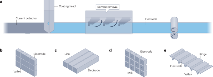
Conventional slurry-based processed electrodes with various modifications. a, Conventional slurry-based processing with a slot-die coater. b–d, Grid (panel b), line (panel c) and hole (panel d) patterns from laser ablation. e, Electrodes with ridges (regular coating) and valleys (thinner or no coating) from co-extrusion.
Grooves can also be created through co-extrusion (Fig. 2e), in which electrodes are simultaneously coated with ridges (regular coating) and valleys (thinner or no coating). Compared with laser ablation, co-extrusion does not require additional equipment and is compatible with the state-of-the-art coating for battery electrodes. Similar to laser ablation, the grooves are still too big to avoid convergence of the two adjacent ridges during coating76.
Freeze casting is another technique to create vertical channels in which wet coatings are placed in a cold environment, below the solvent melting point, and the solvent is removed through sublimation14. Vertical channels can be created with appropriate formulation (for example, the solid to water ratio) and operation conditions (for example, the coating speed and cooling temperature) and boost charge and discharge rate performance73. However, whereas solvents can be frozen relatively quickly, even in a roll-to-roll process, the sublimation process takes time (hours and even overnight) even under vacuum64. Thereby, the throughput will be much lower than the state-of-the-art roll-to-roll process. Moreover, electrodes prepared through freeze casting usually show high porosity and weak mechanical strength64. Calendering is also not practical for freeze cast electrodes as the pore structure can be destroyed. Reducing porosity relies on the slurry formulation and infiltration process13. The adhesion strength could also be low due to the small contact area between the coating and the current collector14. Alternatively, a two-layer electrode has been proposed with a bottom dense layer, processed through conventional coating to maintain good adhesion, and a top layer prepared through freeze casting14. However, the energy consumption, manufacturing cost and battery performance need to be optimized for future commercialization. Additive manufacturing is discussed in the 3D-printing processing section below. Compared with conventional electrodes, the current distribution is not uniform in electrodes with open architectures78. The local negative/positive electrode areal capacity ratio also varies and might lead to lithium plating5,73.
Electrode coating is a critical step in battery manufacturing with impact on the electrochemical performance and manufacturing cost. Currently, slurry preparation is made through a batch process and takes multiple hours, with batch-to-batch variation5. A continuous process could improve the homogeneity of slurries, and throughput in electrode coating5. Designing new electrode processing processes and using multifunctional components could simplify electrode and cell design79. Developing or modifying electrode processes to ease recycling at the battery’s end-of-life cycle could also be helpful80 (Box 1). In addition, integrating in-line metrologies for quality control could reduce electrode scrap and the manufacturing cost81.
Dry processing
Switching to solventless electrode processing could reduce the manufacturing cost and environmental impact82. Powder-to-film processing is one of the main dry processing methods and a roll-to-roll electrode preparation route. There are two main steps in the powder-to-film process: dry mixing and powder-to-film operation. This process does not use solvents, fits the Intrinsically Safer Design principles83,84,85 and reduces the LIB manufacturing footprint as it eliminates electrode drying5. Compared with conventional wet processing, dry electrode processing can reduce manufacturing costs of LIBs by ~11.5% and energy consumption by more than 46%86, potentially saving 4.76 million tons of annual carbon dioxide emission by 2030 (ref. 87). Moreover, electrodes prepared through powder-to-film processing can have lower binder content (even <1 wt%) and do not experience binder migration, have low tortuosity (Fig. 3a) and show even electrode material distribution (Fig. 3b) with good mechanical strength88,89. Powder-to-film processing is able to lead to an increase of the electrode’s capacity by more than 20% (Fig. 3d,e), due to an improvement of the electrode strength by up to 50% and a decrease of impedance by 30–50%83. Compared with conventional processing, the dry processing time is relatively short, from hours to minutes88,89.
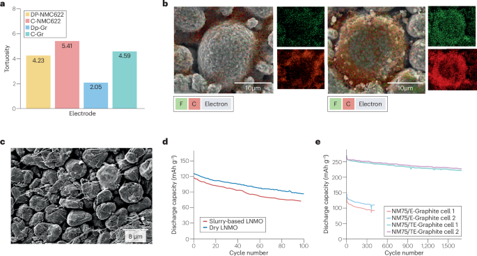
Dry-processed electrode morphological properties affect their electrochemical performance. a, Tortuosity comparison between conventional electrodes and dry-processed electrodes at comparable electrode porosity, thickness and active material loading. b, Material distribution in conventional (left) and dry-processed electrodes (right). c, Cross-sectional scanning electron microscopy image of a Maxwell-type graphite dry-processed electrode. d, Improved cyclic performance of dry-processed lithium nickel manganese cobalt oxide (LNMO) electrodes. e, Electrochemical performance of a lithium-ion battery full cell, incorporating a graphite anode with (NM75/TE-Graphite cell 1 and cell 2) and without (NM75/E-Graphite cell 1 and cell 2) a polymer-based protective coating. Dry processing exhibits various advantages for manufacturing and can deliver electrodes with enhanced electrochemical performance. C, carbon; F, fluorine. Panel a adapted with permission from ref. 15, Elsevier. Panel b adapted with permission from ref. 41, IOP Publishing. Panel c adapted with permission from ref. 15, Elsevier. Panel d adapted with permission from ref. 105, Royal Society of Chemistry. Panel e adapted with permission from ref. 114, Elsevier.
Dry mixing
Dry mixing is a crucial first step in dry processing, and impacts the morphology and structure of the electrode component mixture85,90. Usually, dry-processed electrodes have a more uniform electrode component distribution than conventional wet-processed electrodes41,43 (Fig. 3b). In conventional wet processing, mixing for material dispersion is performed in a solvent through stirring (hours to overnight), whereas dry mixing homogenizes electrode components in a rapid manner (level of minutes) in a solvent-free condition using various commercial mixers15 (Fig. 4), such as ball millers (Fig. 4a), extruders (Fig. 4d) and blade blenders (Fig. 4b). Each mixer has different dry mixing conditions depending on their working mechanism, which complicates balancing the electrode composition, mixing sequences and degree of mixing85. Insufficient dry mixing results in agglomerated and unevenly distributed electrode components, whereas excessive dry mixing can damage the active materials and binder particles, compromising the electrode’s mechanical strength and LIB performance85. For example, performing different dry mixing sequences, such as mixing all electrode components at once or mixing the active electrode material and binder first, before adding the conductive carbon, can influence the physical and electrochemical properties of the dry-processed electrodes90. The impact of mixing the active material and the conductive carbon first, and then adding the binder, or mixing the binder and the conductive carbon first, and then adding the active material, is still unclear91.
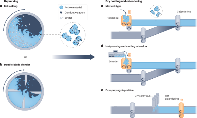
Mechanism of various dry processing methods. a, Ball milling-based dry mixing. b, Double-blade blender-based dry mixing. c, Maxwell type. d, Hot pressing and melting extrusion. e, Dry spraying deposition. Adapted with permission from ref. 89, Elsevier.
The properties of the electrode components, such as particle size, material morphology and surface energy, can also influence the dry-processed mixture92,93,94,95. It is important to optimize the dry mixing step of non-conventional electrodes, such as silicon anodes and sulfur cathodes, which undergo large volume fluctuations during cycling96,97,98,99. Optimizing the degree of fibrillation of the binder polytetrafluoroethylene (PTFE) can maximize the mechanical strength and cyclability of the electrodes, while also improving charge and discharge rate capabilities and energy density85.
Powder-to-film operation
The three main processes in powder-to-film operation include Maxwell type, hot pressing and melting extrusion, and dry spraying deposition.
Maxwell-type dry processing is a scalable and reliable powder-to-film method100, with three main steps: mixing powders; calendering the dry-mixed electrode components into free-standing electrode films; and laminating the free-standing electrode films onto carbon-coated current collectors (Fig. 4c). This process relies on binders, particularly PTFE, that enable a binding mechanism of deformation. During dry mixing and calendering, PTFE particles transform into fibres and create a robust framework to bind the active material and conductive carbon15,101 (Fig. 3c). Owing to a temperature-induced phase transition, high molecular mass PTFE particles soften into long-range entangled fibres that improve the electrode film’s robustness102,103,104. The Maxwell-type method enables electrode processing at ambient or near-ambient conditions, and produces electrodes with enhanced rate performance15 and long-term cyclability105 in high-loading LIBs due to the reduced tortuosity, uniform material distribution and good mechanical strength (Fig. 3d).
The dense structure and even material distribution of dry-processed electrodes favour high mass-loading LIB performance, and it is expected that the energy density could surpass that of conventional wet-processed LIBs15,105. However, there are some drawbacks, including fracture of the active material particle structure and decomposition of the PTFE binder. Particle fracture is mainly caused by compression during calendering of the dry-mixed electrode components into free-standing electrode films and lamination of the free-standing electrode films onto carbon-coated current collectors106. Single-crystal active materials can address this issue due to their fine primary particle structure with a considerably small (1–4 μm)107,108 particle size109,110. Unlike PVDF binder, PTFE binder participates in side reactions that affect the reversible charge and discharge capacity and long-term cyclability of LIBs, especially of carbon-based anodes111,112,113.
To mitigate PTFE decomposition in carbon-based anodes, several approaches have been developed, including coating graphite with a polymer-based protective coat114,115 (Fig. 3e) or using hard carbon or soft carbon as electrode materials116. The first approach relies on polymers’ lithium-ion conducting and electron insulating properties, but increases the manufacturing costs and might restrict the charge and discharge rate capability of high-loading dry-processed electrodes114,115. The second approach to mitigate PTFE binder decomposition is based on the small volume expansion of hard carbon and soft carbon during cycling, and delivers a limited charge and discharge capacity116. Alternatively, a binder mixture of PTFE and PVDF can stabilize graphite anodes during cycling117. In this case, PTFE is responsible for binding the free-standing electrode films, whereas PVDF, due to its thermoplastic behaviour, delivers a binding effect by melting around the surface of graphite particles117. Designing new fibrillizable polymer binders and electrolytes could also be an effective approach to stabilize PTFE-based graphite anodes. This approach might be more affordable and easier than using the polymer coating strategy for LIB manufacturing. Overall, whereas Maxwell-type dry processing is more commonly used for cathode fabrication, the production of both anode and cathodes through dry processing has been demonstrated at the industrial scale18.
Hot pressing and melting extrusion are also commonly used and scalable techniques that share similarities with the Maxwell-type dry processing method89. The main difference is in the binder’s binding mechanism (Fig. 4d). Hot pressing and melting extrusion approaches require thermoplastic binders, such as PVDF118, polyethylene oxide119, polypropylene120 and the conductive polymer polyaniline121. During the high-temperature pressing step or rolling of the dry-mixed electrode mixture, the binders melt and fuse electrode materials together to form free-standing electrode films. To ensure the mechanical strength of dry-processed electrodes, studies have demonstrated that the addition of multi-walled carbon nanotubes could potentially be helpful due to the formed nano hook-and-loop fastening effect118,122. However, there are still concerns about the facileness, affordability and energy density of these approaches. The duration of the heat treatment or total thermal energy input should be controlled and optimized123, as this could reduce the LIB electrode production speed and increase manufacturing costs. Additionally, limited understanding of the properties of the electrolyte passivation layers on the electrode and the side reactions caused by these thermoplastic binders (except by PVDF) could slow down commercialization. Ultimately, this dry processing approach is still a challenge for next-generation LIB manufacturing.
Dry spraying deposition is another dry processing route (Fig. 4e) and primarily uses electrostatic spray deposition. This method involves coating an electrically grounded current collector with a high-voltage charged (~30 kV) powder mixture of electrode materials, and a series of thermal treatments and calendering steps to melt the binder and control the electrodes’ porosity89. This dry processing strategy also relies on binders with thermoplasticity, such as PVDF124. High molecular weight PVDF binders, such as PVDF HSV900 (a mixture of two types of PVDF polymers with different molecular weight values: 1,367 and 92,840 kDa (ref. 125)), can facilitate the formation of pores and contribute to the improvement of LIB performance126. Despite some results showing that electrostatic spray deposition-based dry-processed electrodes can lead to an enhanced LIB performance41,127, challenges remain because of the difficulty in scalability118. Specifically, electrostatic spray deposition’s roll-to-roll production speed is much slower (6–12 m h–1)88,128 than conventional wet processing (~10–30 m min–1)5, which halts its use in high-throughput LIB manufacturing. Although high-temperature calendering (about 200 °C; with the PVDF melting point being 177 °C) can be an alternative to the heat post-treatment applied to improve electrodes’ mechanical strength and reduce the manufacturing process time, the required manufacturing costs and energy input are substantial129. Modified dry deposition strategies, such as pulsed-laser deposition130 and sputtering131,132, have also achieved high-quality LIBs. However, these strategies remain limited to laboratory-scale research or specialized applications in microelectronic devices and integrated circuits, due to high costs and lack of scalability5,118. As a result, dry deposition as a dry processing method might have limited impact on high-throughput LIB manufacturing.
In addition to the three dry processing strategies mentioned above, dry processing has been coupled with other techniques, such as 3D printing and radiation curing. These exploratory works could facilitate and optimize LIB manufacturing, and are discussed separately in the sections below. Furthermore, graphene materials can enable binder-free dry processing of high mass-loading and free-standing electrodes at room temperature133,134,135. However, the practicality is unclear given the large amounts of nanostructured materials and precursors needed to obtain electrodes with good mechanical strength. The higher quantity of electrode materials limits the LIB energy density and adds extra costs and environmental concerns. Moreover, the edge quality, such as alignment and homogeneity of the electrodes, from dry processing could be lower compared with that of conventional slurry-based processing and advanced aqueous processing15,136. This limitation might create more scrap. Overall, owing to Maxwell-type dry processing’s scalability, affordability and ease of use, it is anticipated that this strategy could gradually replace conventional wet processing in high-throughput LIB manufacturing. Substantial efforts are required to industrialize the other dry processing approaches. Dry processing research and development could also benefit the manufacturing of electrodes and electrolytes for solid-state LIBs137,138,139,140 and other energy storage systems136,141,142.
Radiation curing processing
Radiation curing processing can use either ultraviolet (UV) light or electron beam irradiation. Radiation curing processing uses small molecules, such as monomers, oligomers, low molecular weight polymers and photoinitiators as precursors if UV light is used as the radiation source143 (Fig. 5a). In the slurry, these molecules undergo chemical polymerization and cross-linking to form high molecular weight polymers that act as the electrode binder144. This approach has the potential to minimize or eliminate the need for solvents in coating formulation and deposition144. Radiation curing processing can also save up to 65% of the energy compared with thermal oven drying145. Moreover, it enables high-speed manufacturing (demonstrated at up to 167 m min–1)145 and requires a lot less plant floor space (down by 85%) for equipment than drying ovens146 (Fig. 5b).
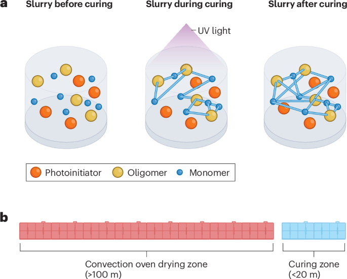
Radiation curing processing working principles. a, Mechanism for ultraviolet (UV) curing processing. b, Size of lithium-ion battery electrode processing equipment for beam curing processing (blue) and conventional wet processing (red).
As radiation curing is a completely different mechanism compared with other processing methods, the binder chemistry needs to be carefully studied for compatibility in LIBs. To assess the stability of radiation-cured polymers in LIB half cells, cyclic voltammetry or similar electrochemical tests should be conducted. Even if no additional redox peaks are observed in the initial cyclic voltammetry scan, the absence of peaks only indicates good short-term electrochemical stability and cannot guarantee long-term stability. The cured products must be electrochemically stable within the voltage window of the active materials, typically 2.0–4.5 V for most cathode materials144.
UV curing
UV photopolymerization involves a series of chemical reactions, starting with UV light interacting with a photoinitiator to form free radicals143. In UV curing, acrylated monomers and oligomers are used as the binder and mixed together with photoinitiator additives and a solvent, such as acetate or alcohol147. Acrylate-based chemistry is the primary choice for radiation curing precursors, although other functional groups may be present in commercial products147. The free radicals formed by the photoinitiator propagates through the acrylate group of monomers and oligomers, resulting in cross-linking between them143. The polymerization process is completed when the free radicals are depleted. The resulting slurry is coated onto an aluminium current collector, using a slot-die coater, and the UV beam irradiation is applied to complete the photopolymerization of the acrylated UV binder147. The resulting electrodes have good mechanical properties, strong adhesion to the current collector and minimum swelling when soaked in the battery’s electrolyte for 2 weeks147. These qualities demonstrate the robustness of the UV-cured acrylate binder for LIBs.
Owing to the dark colour of cathode materials and conductive carbon, the penetration of UV light is limited. The penetration depth of UV light depends on the extinction coefficients of the photoinitiators and the thickness of the active cathode materials and the UV-cured binder filled with carbon143. Typically, curing of an electrode approximately 30 μm thick can be achieved in one passage under UV beam irradiation. UV curing can also be applied to bilayer electrodes to achieve higher areal capacities147. Moreover, a good rate capability and capacity retention (90%) over 180 cycles with double-sided bilayer LiNi0.5Mn0.3Co0.2O2 cathode coatings (14.6 mg cm–2 per side or 2.34 mAh cm–2 per side) are achieved in full 1 Ah pouch cells with a cathode active material content of 94 wt%147. UV curing technology can also be employed for LIB separator processing148.
Electron beam curing
Compared with UV curing, electron beam curing offers the advantage of being initiator-free and having a tunable penetration depth based on the accelerating voltage149,150. Electron beam equipment, operating at >200 keV, can achieve the curing of composite electrodes with 25 mg cm–2 (~4 mAh cm–2)151, making this approach especially useful for higher areal loading electrodes144. Self-shielded electron beam machines have been developed and commercialized, operating with high reliability and low maintenance in roll-to-roll production environments145.
Successful electron beam curing of the LiNi0.5Mn0.3Co0.2O2 cathode has been demonstrated using an electron beam curable acrylated polyurethane binder144. The electrochemical performance of the electron beam-cured electrode was comparable with that of a conventional PVDF-based electrode145. Both electrodes exhibited similar first charge capacities and Coulombic efficiency, and the electron beam-cured electrode demonstrated excellent cyclability, delivering similar capacity over 100 cycles145.
High-speed electron beam curing strategies have been demonstrated by industrial stakeholders in 1.5 Ah LIB pouch cells145. The cyclic performance of electron beam-cured electrodes with a high areal loading of >4 mAh cm–2 in 2 Ah pilot-scale pouch cells is comparable with the performance of LIBs from the well-established conventional wet processing19. Non-electron beam-cured electrodes exhibit rapid capacity decay, due to the poor binding performance rooted in the lack of a cross-linked polymeric binder network145. Moderate capacity fading is observed for the first tens of cycles in a high-speed electron beam-cured electrode sample at 500 fpm in O2 gas. The embedded dosage indicators proved that the electron beam penetration along the electrode was uniform. However, the oxygen level was found to be as high as 810 ppm in the electron beam chamber during the curing treatment. Free radicals generated from the electron beam can be scavenged by oxygen, which strongly inhibits further chain propagation of acrylate groups. An effective polymeric binder network was not formed due to the presence of oxygen, causing capacity decay145.
An alternative electron beam curing processing procedure was performed at a line speed of 400 fpm, delivering a much lower oxygen level (<200 ppm) in the chamber. A 1.5 Ah pouch cell prepared using this processing protocol shows an improved cyclic performance compared with the electrode cured at 500 fpm, which is comparable with that of the conventional PVDF-based electrode145. Formulating an electron beam-induced covalently interconnected network with silicon anode material and gel polymer electrolyte can benefit high-energy LIB electrodes with next-generation active materials by enhancing mechanical stability and electrochemical kinetics152. The combination of dry processing or other high-speed deposition methods with high-speed electron beam curing could be a way to further pursue better electrochemical performance.
In electron beam and UV curing processing, it is important to ensure the penetration of the beam dose in the thickness direction of the electrode144. Increasing the electron beam dose can result in more free radicals, during radiation curing, to counteract oxygen’s inhibition of free radical propagation145. An inert environment, typically using nitrogen, can be employed to reduce oxygen levels in the curing chamber145. Furthermore, additives and electron beam curable cationic resins are being investigated as they are not reactive towards addition reactions but are reactive towards hydrogen abstraction145.
In summary, electron beam curing for LIB electrode processing offers initiator-free features and a tunable penetration depth. Challenges such as oxygen inhibition need to be addressed.
3D-printing processing
Additive manufacturing technologies enable different electrode patterns or architectures such as the microgrid153, digit154, line155, spiral156, hierarchy157 and fibre158 (Fig. 6a–g). The major advantage of this technology is its versatility in structural designs and the high customizability that minimizes material waste159. This section outlines 3D-printed electrodes through different printing methods, including direct ink writing, material jetting techniques, such as inkjet printing and aerosol jet printing, and fused deposition modelling. Other 3D-printing processing methods such as stereolithography and template-assisted electrodeposition are also discussed.
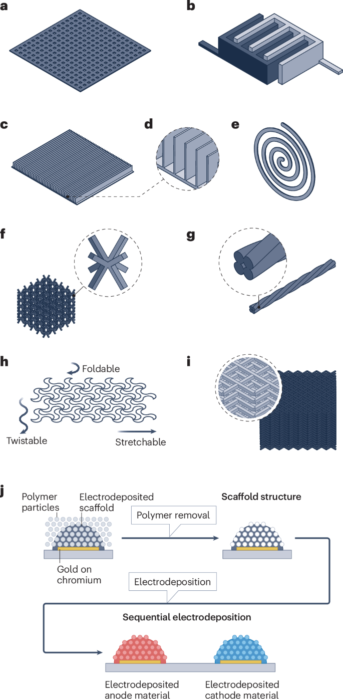
3D-printed electrodes have different structural features. a, Microgrid. b, Digit. c, Line. d, Cross-sectional view of the line structure. e, Spiral. f, Hierarchical. g, Fibre. h, Flexible direct ink writing processed electrode. i, Stereolithography printed and pyrolysed hard carbon electrode for sodium-ion batteries. j, Template-assisted electrodeposition porous electrode. Panel b adapted with permission from ref. 165, Wiley. Panel g adapted with permission from ref. 158, Elsevier. Panel h adapted with permission from ref. 164, Elsevier. Panel j adapted from ref. 179, Springer Nature Limited.
Direct ink writing
Direct ink writing, which uses a pneumatic or mechanical actuated syringe for ink (slurry) dispensing, is widely used in electrode fabrication due to its simplicity and material versatility160. Direct ink writing technology dispenses ink only where it is needed, reducing material waste compared with traditional wet processing in which the coating shape cannot be controlled. This technique requires ink with high viscosity and shear thinning properties, which are typical characteristics of electrode slurry in conventional wet processing, making design and preparation for LIB manufacturing simpler5,161.
Direct ink writing can prepare multilayer thick electrodes with ease, such as a 10-layer 1.5 mm thick, 4.74 mAh cm–2 micro-lattice Li4Ti5O12 electrode integrating reduced graphene oxide and silver nanowire162 and a 20-layer 320 μm thick, 4.3 mAh cm–2 linear-patterned LiNi0.8Mn0.1Co0.1O2 electrode163 (Fig. 6c,d). With grooves for fast lithium-ion transport, the high mass-loading 3D-structured LiNi0.8Mn0.1Co0.1O2 electrodes exhibit a better rate capability and long-term cyclability than a conventional planar electrode with the identical areal loading. The direct ink-printed thick electrodes can also mitigate binder migration during the drying step, reducing the risk of poor mechanical strength and high impedance in the electrode5,163. Additionally, the freedom of pattern design enables flexible or stretchable electrodes for wearable devices164 (Fig. 6h). Moreover, with high-resolution features, direct ink writing is suitable for microbatteries. With the assistance of a 30 µm ultrafine nozzle, a multilayer interdigitated microbattery has been fabricated with five pairs of interlocked electrode lines at a size of 960 µm × 800 µm (ref. 165). However, high resolution is achieved with a trade off with throughput.
Introducing free space into electrodes via direct ink writing can affect the volumetric energy density, although power density is improved163. Direct ink writing applications typically contain a higher (>15 wt% combined) content of binders and conductive additives than industrial wet processing, which ensures viscosity and mechanical strength but reduces energy density160. Freeze-drying is often implemented as a post-treatment to prevent electrode structure collapse, further escalating the manufacturing cost163. Considering the high manufacturing cost and low throughput, direct ink writing is only suitable for certain types of LIBs, such as high-power LIBs and micro-LIBs.
Material jetting
Material jetting technology, including inkjet printing and aerosol jet printing, is also widely used for electrode printing, and similar to direct ink writing can deposit materials only where needed, minimizing waste166. Inkjet printing mostly uses a piezoelectric actuator to dispense material in the form of droplets. The low viscosity of ink at several tens of mPa∙s is suitable for thin and large-area printing but not for manufacturing thicker electrodes167. An aqueous inkjet printable ink has prepared a thin-film LiFePO4 electrode, exhibiting excellent rate capability and long-term cyclability168. Acoustophoretic inkjet printing can broaden the viscosity window to 25 Pa∙s (ref. 167), although no electrode using this new technology has been reported due to limited accessibility.
By contrast, aerosol jet printing applies an atomizer and gas flow to generate aerosolized droplets and has a wider ink viscosity window, less restricted particle sizes and larger stand-off distances169, making it suitable for high mass-loading electrodes170. Although aerosol jet printing has not been broadly applied, it can produce hierarchical micro-lattice electrodes with superior areal capacity (~5 mAh cm–2) compared with the baseline solid block electrode157 (Fig. 6f). However, the versatility of aerosol jet printing is still constrained by the limited range of available ink types, and the high cost of aerosol jet printers can be a hindrance171.
Fused deposition modelling
Fused deposition modelling, which is commonly used in commercial 3D printing, has been applied to electrode fabrication. Fused deposition modelling offers a low cost, a fast printing speed and large-size capability172. Additionally, recycling fused deposition modelling parts with various types of materials has been extensively investigated173. However, the filament used in fused deposition modelling contains a high content of electronic-insulating thermoplastics as a base material172. To counter high resistance, the filament requires conductive active materials or a large amount of conductive additive, limiting the material versatility and energy density159. Post-treatments to remove insulating thermoplastic content could improve the charge and discharge capacity174 due to the increased conductivity. However, these highly toxic chemical post-treatments increase LIB manufacturing costs and emissions. Alternatively, properly adjusting the ratio of filaments, active material, plasticizer and conductive additive, as well as using a suitable conductive additive and plasticizer, was successful in extracting 200 mAh g–1 of reversible capacity at 0.05 C (~54% of graphite’s theoretical capacity, 372 mAh g–1), which is high for a 250 µm thick, fused deposition modelling printed electrode175. The electrochemical performance of fused deposition modelling printed electrodes still cannot match that of conventional electrodes, making it clear that more research and development is necessary for the application of fused deposition modelling in LIB manufacturing.
Other printing techniques
Stereolithography is a resin printing technique that uses a UV laser to cure materials at certain positions with a fine surface and high accuracy159. However, unlike the thermoplastic for fused deposition modelling, stereolithography typically uses thermoset polymers, which make recycling challenging176. Stereolithography also requires large amounts of organic compounds including various types of monomers, oligomers, photoinitiators and other additives in resins177, which could complicate the design and preparation of the resin. Moreover, post-treatments of stereolithography parts include washing and secondary curing, further complicating the manufacturing process. Although direct application of stereolithography in LIB electrode processing has not been reported, a hard carbon micro-lattice electrode made using pyrolysing stereolithography has been applied to sodium-ion batteries178 (Fig. 6i). Such a method might be transferable to LIBs for similar carbon-based active materials, but its limitations in material variety and energy-intensive and time-consuming post-treatments make it less attractive for scaling up178.
Template-assisted electrodeposition is another additive manufacturing method, which has been used to prepare a manganese dioxide (MnO2) and nickel–tin micro-LIB179 with self-assembled polystyrene particles as the template for nickel electrodeposition. Consecutively, the polymer template is removed by chemical rinsing and etching, and the acquired nickel scaffolds are further used as a substrate for nickel–tin and MnO2 material depositions (Fig. 6j). The LIB exhibited excellent rate capability up to 1,000 C and high energy and power densities due to the porous structure and highly conductive metal scaffold179. However, template-assisted electrodeposition involves complicated operations and highly corrosive NaOH, rendering it unsuitable for sustainable and cost-effective high-throughput LIB manufacturing179. Furthermore, optimization is still necessary to meet the specific needs of high-power LIBs in terms of volumetric energy density in highly porous electrode architectures.
Road to market
3D printing of LIB electrodes is in its infancy at the laboratory scale, with a notable absence of facilities for mass production161. The production speed of 3D printing is still slow compared with conventional roll-to-roll wet processing methods. Despite this, its high customizability and low upfront cost make it suitable for prototyping and small-quantity production for special applications. The high printing resolution also facilitates micro-LIB manufacturing, exceeding the capabilities of traditional methods161. Among the electrode printing techniques discussed here, direct ink writing and material jetting methods currently lead in terms of simplicity, electrochemical performance and scalability. To maximize customizability and flexibility, large-scale processing of structured 3D-printed electrodes could be facilitated by developing specific 3D printers for LIB manufacturing161. The printers should employ multiple print-head set-ups to enhance production speed and enable multi-material printing to bypass the assembly and packaging steps159. Additionally, although 3D printing exhibits high precision, structural deformation of electrodes should be taken into consideration because it can cause lithium plating issues. These issues arise from the variation of the deformed sites’ negative to positive electrode capacity ratio, which requires further optimization of ink composition and slurry rheology163. Despite the required efforts, there remains a long way to go for the industrialization of 3D-printed LIB electrodes.
Summary and future perspectives
Electrode processing is a key LIB manufacturing step that has an impact on the electrochemical performance, manufacturing cost and energy consumption. Developing advanced electrode processing strategies is essential to achieve processing facileness, affordability and scalability. This Review outlines four strategies — advanced aqueous processing, dry processing, radiation curing processing and 3D-printing processing (Table 1). Conventional slurry-based processing is the most mature and common technique, and advanced aqueous processing is very similar to conventional slurry-based processing in operation and can use the same equipment. Replacing NMP with water eases safety requirements9. However, challenges remain for cathode manufacturing because of the reactions of the cathode active material in water5.
Dry processing is still in the early stages of development, particularly the hot pressing and melting extrusion and the dry spraying deposition methods. Maxwell-type dry processing, which can use the same equipment as conventional slurry-based processing, is potentially scalable and affordable5. However, mixing dry powder could create mixer durability and powder homogeneity challenges, in addition to other problems (for example, PTFE binder decomposes in carbon-based anodes during cycling) related to material compatibility and integrity111. Dry processing can reduce emissions by eliminating the solvent removal step compared with conventional slurry-based processing5, although the throughput has yet to be demonstrated. Dry processing can fabricate thick electrodes with good electrode integrity and minimal binder migration41. Beam curing processing can enable higher throughput as a result of a fast cross-linking mechanism. However, it is still challenging to completely eliminate the solvent and maintain appropriate slurry rheological properties for electrode deposition145. Encapsulating air and solvent into close pores during cross-linking and controlling pore structure and porosity are other concerns that need to be addressed. 3D-printing processing enables high-resolution electrode structures, but at a low throughput163. 3D printing is not suitable for regular electrode manufacturing but would be suitable for special electrode designs with different shape, geometry and structure.
Dry processing might also help with solid-state battery manufacturing as it eliminates incompatibilities between dispersion solvents, electrolytes and binders142. In solid-state batteries, dry processing offers a solution to prepare solid-state electrolyte–electrode interfaces without using liquid electrolytes, which is a challenge in traditional slurry-based processing89. Moreover, for solid-state batteries with polymer-based electrolytes, given that the electrolyte is very thin, the radiation curing process could be helpful in fabricating polymer electrolytes. By coating the cathode and electrolyte simultaneously, the interface could have better contact compared with when the cathode and electrolyte are fabricated separately and assembled together. For example, oxide-based electrolytes require high-temperature sintering, and given the brittle nature of ceramics, it is challenging to cut the oxide electrolyte after sintering and assemble with cathodes180.
Besides electrolytes, mixing a thick cathode with a catholyte (an electrolyte added to a cathode to improve lithium ionic conductivity) improves lithium-ion conductivity. It is important to design a cathode structure that enables low tortuosity with a relative low volume fraction of catholyte137,181. To this end, optimizing the particle size, particle size distribution, electrode formulation and porosity or designing a multilayer structure could be effective approaches66. However, creating a stable and low-resistance interface between the solid-state electrolyte and the anode and cathode remains a challenge due to their different chemistries and electrochemical potential182,183. Using different electrolytes facing the lithium anode and the composite cathode could be a short-term solution. Given the inevitable volume change during charge and discharge, which creates strain and stress at the interface184, designing hybrid cells, where the electrolyte consists of a solid-state electrolyte and a gel or liquid electrolyte, for almost solid-state batteries instead of all solid-state batteries is easier to implement185.
Artificial intelligence and machine learning can accelerate the processes and reduce the costs of LIB manufacturing by eliminating some time-consuming trial-and-error experimental processes186. In LIB electrode manufacturing, artificial intelligence and machine learning can be used for expediting the development of new materials by providing property predictions including voltage, capacity, conductivity and electrochemical stability186. This approach can improve the accuracy and versatility of the traditional density functional theory method for structure prediction187, and also facilitate the prediction and optimization of electrode-related parameters, such as electrode composition188, coating parameters189, calendering parameters190 and electrolyte infiltration191. Artificial intelligence and machine learning can also optimize solid–electrolyte interphase formation parameters192 and predict the degradation behaviour, state of charge and state of health of batteries for safety and remaining useful life evaluations193.
Despite the advantages, artificial intelligence and machine learning face some challenges, such as data scarcity. As a data-driven method, they require a large amount of data for model construction. As a result, artificial intelligence and machine learning are mainly applied to conventional wet processing due to its maturity and relative abundance of datasets188,191. Even so, the dataset can still be inadequate and not fully publicly available. Lack of access to datasets can be a costly hindrance for start-up companies and researchers186. Developing algorithms for small datasets or incorporating theoretical data into the actual dataset are potential solutions to data inadequacy. More freely available datasets and set standards for electrode performance tests should also be considered194.

Responses