Altermagnetic perovskites

Introduction
Perovskites, a large family of compounds with the chemical formula ABX3 as their mother phase, show versatile physical properties and serve as one of the most well-studied textbook materials in condensed matter physics1. In particular, transiton-metal-based (TM-based) perovskites exhibit a wide range of functional properties2,3,4, e.g., ferroelectricity, metal-to-insulator (MI) transition, magnetoelectric effect, spin crossover phenomenon, superconductivity, and photovoltaic effect. In recent years, a new chapter has been added to them5,6: “altermagnetism”.
Altermagnets7 refer to magnetic materials which appear to be conventional collinear Néel-type antiferromagnets but actually break the time-reversal (TR) symmetry due to the lattice structure behind the antiferromagnetic (AFM) order. This happens in a wide variety of materials, whose schematic view is shown in Fig. 1a8. The cause of TR symmetry breaking is that the two sites where up and down spins exist are not connected by inversion or any translation operation, while they are connected by mirror, glide, or screw operation. Therefore, the net magnetization is canceled out, in the limit of zero relativistic spin-orbit coupling (SOC) (in the presence of the SOC, there are cases where small spin canting appears and net magnetization becomes nonzero). In this situation, unlike the local TR symmetry breaking in conventional antiferromagnets, here the macroscopic TR symmetry is broken (we note that if the PT symmetry, which is the combination of the macroscopic TR symmetry T and space-inversion symmetry P, is preserved, the spin splitting is prohibited even when T is broken, and such a system is not classified as an altermagnet7). Consequently, altermagnets show cross-correlation phenomena unexpected in conventional antiferromagnets but rather reminiscent of ferromagnets. Therefore, in contrary to Néel’s statement in his Nobel lecture on antiferromagnets: They are extremely interesting from theoretical viewpoint, but do not seem to have any application9, now they are attracting much attention as antiferromagnets with possible applications.

a A minimal altermagnet, where spin moments locate on different anisotropic electronic orbitals, represented by ellipses, which can be owing to oriented molecules or ligand structures. The shaded rectangle denote the unit cell common for the crystal structure and the magnetic order (q = 0). b A d-wave-type spin-split band structures for up and down spin electrons in an altermagnet. c Schematic illustration of altermagnetic perovskites. The red and blue curved arrows represent the sublattice-dependent spatially anisotropic hoppings of up and down spin electrons, respectively, that render perovskite as altermagnet.
A notable property of altermagnets is the non-relativistic spin splitting appearing in their band structure, resulting in a novel mechanism of spin current generation, independently proposed by Ahn et al. in a rutile-type oxide RuO210 and Naka et al. in an organic antiferromagnet κ-(ET)2X8 in 2019. Figure 1b shows the schematic spin-split band structure in altermagnets, which occurs even in the absence of the SOC, in stark contrast to the relativistic spin momentum locking, e.g., the Rashba effect. As discussed in ref. 8 based on the Hubbard model, the splitting originates from a cooperative effect of an AFM ordering and spatially anisotropic electron hoppings that are sublattice dependent, which can also be interpreted as an AFM analog of the exchange splitting in ferromagnets. The resultant d-wave like anisotropic spin splitting in the Brillouin zone enables us to generate a spin current under an external field.
Another feature of altermagnets is the anomalous Hall effect (AHE) proposed by Smejkal et al., also investigating RuO2 in 2020 (although the preprint version of ref. 11 (https://arxiv.org/abs/1901.00445v1) appeared earlier than those of ref. 8 (https://arxiv.org/abs/1902.02506) and ref. 10 (https://arxiv.org/abs/1902.04436), the non-relativistic spin-splitting of the band structure has been added later in the second version (https://arxiv.org/abs/1901.00445v2)), which is a relativistic effect based on the SOC. Compared to a numerous number of studies on the AHE in non-coplaner and non-collinear antiferromagnets in the last decade12,13, as we will discuss below, the AHE in altermagnets is characterized by the TR and mirror symmetry breaking not only due to the AFM spin pattern but also the background lattice structure14. Since then, enormous amount of papers have been published in a short period15,16,17,18,19,20,21,22, and in 2022 the name, “altermagnet”, has been coined by Smejkal et al. in refs. 7,23 (in this review, we focus on d-wave altermagnets which were found first, while now other types are known to exist21. For example, MnTe is proposed to belong to “g-wave” altermagnets that do not show spin current generation. Now, the definition is expanding even including q ≠ 0 case). Importantly, the spin splitting and its associated spin current generation which do not require SOC and the AHE owing to SOC are different in origin and therefore independent of each other (Table 1). As we will see below, the conditions for their emergence are not equal; there are cases where the spin-current generation is expected but the AHE is not, and vise versa, cases where the AHE is expected even without the spin splitting.
Here we should note that, prior to such recent progresses, some of the essential properties of altermagnets have been pointed out previously based on first-principles calculations: AHE (at finite frequency) based on collinear antiferromagnetism by Solovyev24, and spin-split band structure without SOC in collinear antiferromagnets by Noda et al.25 and Okugawa et al.26. In fact, the perovskites and rutiles were studied as their platforms, in refs. 24, 26 and ref. 25, respectively. The recent novel phenomenon is the prediction of spin-current conductivity8,10 which can be induced by an electric field, sometimes called electrical spin splitter27, or by a thermal gradient8. Its schematic illustration in the perovskite structure is shown in Fig. 1c.
In this Review, we shed light on theoretical progresses on altermagnetic perovskites. First, in the section Early Theoretical Work, we briefly review the early works mentioned above. Next, in the section Perovskite Structure and Model, we introduce the crystal structure of perovskites ABX3 and the canonical microscopic model, i.e., the multiband Hubbard model, to theoretically study the properties of TM-based perovskites with B sites occupied by 3d TM elements. In the section C-type Antiferromagnetic State, the AFM ordering that we mainly discuss here as a typical altermagnetic state in perovskites is explained: the C-type AFM state frequently realized in the (3d)2 case with 2 electrons per TM site. In section Spin Current Generation and Spin-splitting and section Anomalous Hall Effect, we summarize theoretical analyses on the non-relativistic effects and the SOC effects, respectively, based on the model we introduced in the section Perovskite Structure and Model. We stress here that the vast majority of the theoretical studies on altermagnets up to now are based on either first-principles calculations, group theoretical considerations, or simplified model analyses. In contrast, an advantage of studying a realistic effective model is that we can simultaneously pin down the microscopic mechanism of each property and directly give feedback to experiments. We discuss candidate materials and also recent developments in the section Candidate Materials. The section Summary and Perspectives is devoted to the summary of this review.
Early theoretical work
In a pioneering work in ref. 24 more than 25 years ago, the AHE at finite frequency, i.e., the magneto-optical effect, was pointed out to be activated in the canted AFM-ordered states of the perovskites. The optical Hall conductivity σμν (μ ≠ ν) was calculated within first-principles density functional theory in the insulating LaBO3 (B = Cr, Mn, and Fe) with orthorhombic structure, i.e., under the GdFeO3-type distortion that we will discuss in detail in the next section. Figure 2a shows the antisymmetric components of σμν(ω) in the four kinds of spin-ordered patterns that are compatible with the crystal structure. Among them, three states accompanied by weak canting FM moments exhibit the AHE, while the remaining one without weak ferromagnetism does not. Although apparently the weak ferromagnetism is the origin of the AHE here, their magnitudes are comparable to that obtained in the FM state shown in the inset, and it is concluded that the main AFM components are essential. We will discuss this point further in the section Anomalous Hall Effect.
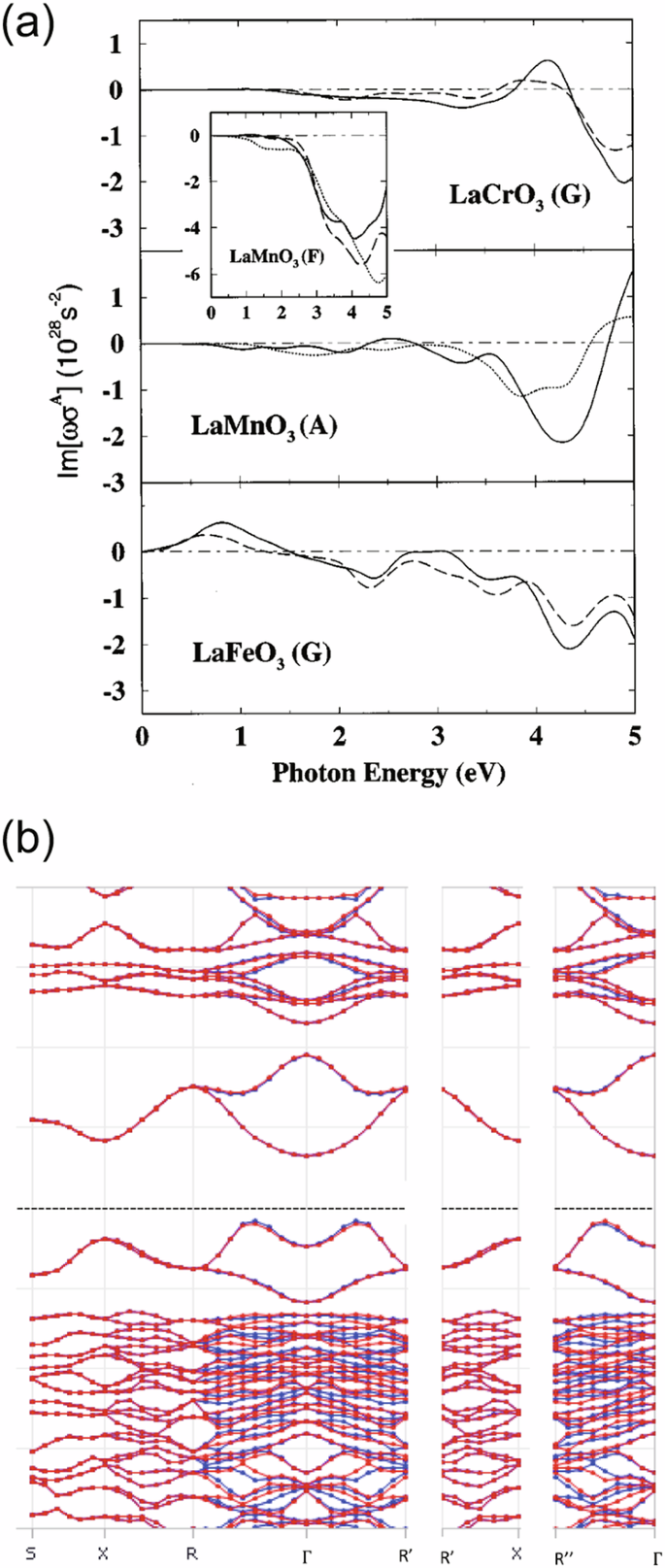
a Optical Hall conductivity at finite ω in various canted AFM states for LaCrO3, LaMnO3, and LaFeO3 in ref. 24 and (b) spin-split band structure for the A-type AFM state in LaMnO3 in ref. 26, obtained by first-principles calculations. In (a), A, G, and F-type are conventional notations for the spin ordering patterns on the perovskite structure (see the section C-type Antiferromagnetic State). Reprinted (adapted) with permission from ref. 24 (copyright 1997 American Physical Society) and from ref. 26 (copyright 2018 IOP Publishing).
More recently, in a series of papers in refs. 25,26, the non-relativistic spin-split band structures in MnO2 including its rutile phase and perovskites, respectively, were pointed out within first-principles band calculations, and their symmetry conditions were discussed in detail. Reference 26 in fact investigates the three perovskite compounds same with ref. 24, in the AFM ordered states; we show in Fig. 2b an example of the spin-split band structure. In all of these studies, the importance of the crystal structure underlying the AFM order has been stressed. In the next section we will introduce its characteristics and the microscopic model incorporating such ingredients in the perovkite ABX3 systems.
Perovskite structure and model
The perovskite structure consists of BX6 octahedra sharing corners to form a three-dimensional framework and A ions occupying the interstitial spaces. The important structural feature which makes perovskite system an altermagnet is the rotational distortion of the BX6 octahedron called GdFeO3-type distortion, commonly seen in many of ABX3 compounds. This has conventionally been known and utilized to control the bandwidth via the tolerance factor, a ratio between the ionic radii of three elements.
The distorted structure of ABX3 is shown in Fig. 3a, in which the regularly aligned BX6 octahedra on the cubic lattice rotate so as to fill the crystal voids around the A sites, as illustrated in Fig. 3b. The distortion is parametrized by the major rotation angle ± ϕ; the additional tilting ψ is uniquely determined by ϕ28. Consequently, the crystal becomes orthorhombic and four independent BX6 octahedra (B1–B4) appear within the unit cell. In Fig. 3, the global axes, xyz, correspond to the crystallographic axes, abc, in the space group Pbnm, or, cab, in terms of the equivalent Pnma. The four octahedra are connected by the b-glide operation perpendicular to the x-axis, the n-glide operation perpendicular to the y-axis, and the mirror operation perpendicular to the z-axis in Pbnm.
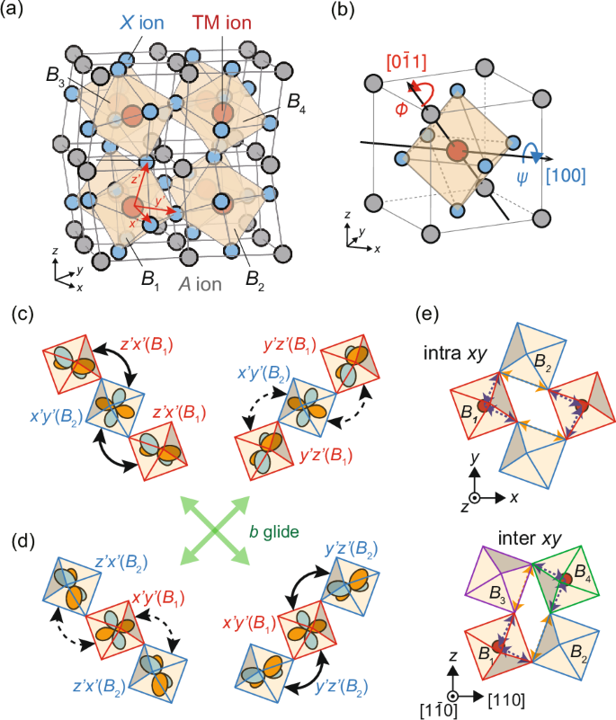
a Perovskite structure with the GdFeO3-type distortion. B1–B4 denote the BX6 octahedra contained in the unit cell, connected by symmetry operations thus crystallographically equivalent. The (x^{prime} y^{prime} z^{prime}) axes represent the local coordinate defined for each octahedron. b Two kinds of BX6 rotation modes of the GdFeO3-type distortion described in the text. Schematic illustrations of the anisotropies of the t2g–t2g transfer integrals on (c) B1–B2–B1 and (d) B2–B1–B2 bonds along the [110] and ([bar{1}10]) directions. The magnitude of the transfer integrals denoted by the solid arrows are larger than those by the dashed arrows in the presence of the distortion. e The real-space hopping paths of the intra- and inter-xy-plane NNN bonds between the transition metal B sites through the ligands X, essential for the AHE.
A standard effective model widely used to describe the electronic states of perovskites is the multi-d-orbital Hubbard model, written as ({{mathcal{H}}}_{0}+{{mathcal{H}}}_{{rm{int}}}+{{mathcal{H}}}_{{rm{SOC}}}) including the SOC effect. The first term describes the electronic hoppings between the d orbitals given by
where ciβσ and ({n}_{ibeta sigma }(={c}_{ibeta sigma }^{dagger }{c}_{ibeta sigma })) are the annihilation and the number operators of an electron on TM site i with spin σ of the d orbital β((=x^{{prime}{2}}-y^{{prime}{2}},3z^{{prime}{2}}-{r}^{2},x^{prime} y^{prime} ,y^{prime} z^{prime} ,z^{prime} x^{prime})), respectively, represented in the local (x^{prime} y^{prime} z^{prime}) axes fixed on the ith octahedron as shown in Fig. 3a. Here we consider not only the nearest neighbor (NN) but also the next-nearest neighbor (NNN) d–d transfer integrals, ({hat{t}}_{ij}^{dpd}(phi )) and ({hat{t}}_{ij}^{dppd}(phi )), respectively, evaluated by the hopping processes through the ligand p orbitals5,6. As we will see later, the NNN terms are crucial for the AHE, whose example of hopping paths is shown in Fig. 3e. Reflecting the BX6 rotations, the transfer integrals depend on the distortion angle ϕ.
An important feature of the NN d–d transfer integrals is their spatial anisotropy depending on the bond directions, owing to the hybridization between the different d orbitals induced by the BX6 rotations. As shown in Fig. 3c, for example, the inter-orbital transfer integral between (z^{prime} x^{prime}) in B1 [(z^{prime} x^{prime} ({B}_{1}))] and (x^{prime} y^{prime}) in B2 [(x^{prime} y^{prime} ({B}_{2}))] in the ([bar{1}10]) direction becomes nonzero, which is zero in the undistorted cubic structure, and is larger than that between (y^{prime} z^{prime} ({B}_{1})) and (x^{prime} y^{prime} ({B}_{2})) in the [110] direction. On the other hand, on the B2–B1–B2 bonds, the magnitudes of the electron hoppings in the [110] and ([bar{1}10]) directions are switched with each other as shown in Fig. 3d, reflecting the b-glide symmetry which connects the B1 and B2 sites. These inter-orbital hybridizations yield the anisotropic transfer integrals between the same sublattice sites, depending on the bond directions within the xy plane.
The onsite Coulomb interactions on d electrons are introduced in the conventional manner as
where U and (U^{prime}) represent the intra- and inter-orbital Coulomb interactions, respectively, J is the Hund coupling, and I is the pair hopping interaction. The SOC can be described as
where the d orbital and spin angular momenta are written as lloc and sloc, respectively, defined in the local (x^{prime} y^{prime} z^{prime}) axes on the ith octahedron.
C-type antiferromagnetic state
To explain the vast variety of electronic properties of perovskites, the multi-d-orbital Hubbard model and their variants have been treated extensively2,4. Here we refer to a series of work by Mizokawa and Fujimori29,30,31, who investigated the spin and orbital ordered phases in 3d TM-based perovskite oxides based on the multi-band d–p model by varying the electron filling factor, namely, corresponding to different TM elements, providing a systematic view of these materials. As for the spin orderings, the basic patterns that they studied are called F-, A-, C-, and G-types. F is the ferromagnetic pattern and the other three are AFM states, with A: in-plane ferromagnetic and inter-plane AFM, C: in-plane AFM and inter-plane ferromagnetic, and G: both in-plane and inter-plane AFM patterns. In the following two sections, we mainly focus on the C-type AFM state, typically stabilized in the case where there exist two d electrons per TM element, i.e., the (3d)2 case. It shows characteristic altermagnetic properties, and also can be viewed as an analog of the altermagnetism in the κ-type organic compounds8,14.
Without SOC, the spin direction is not fixed so we can consider the spin-ordered states as the limit from finite SOC to ζ = 0. In this case spin patterns are collinear; a schematic view of the C-type AFM state in perovskites is shown in Fig. 4a. On the other hand, when ζ ≠ 0, the spins point to certain directions owing to the magnetic anisotropy and show small canting via the Dzyaloshinsky-Moriya interation. Under the space group (Pbnm / Pnma), all the possible AFM spin patterns fall into either of four types32,33. For example, as shown in Fig. 4b when the y-axis spin components align in a C-type AFM pattern, projections to the other components must show ferromagnetic (F) moments along the x-axis and a G-type AFM pattern along the z-axis; it is written as FxCyGz. The others are CxFyAz, GxAyFz, and AxGyCz, as shown in Fig. 4c–e. Indeed, these four patterns are the ones investigated by Solovyev24, who found that the first three are AHE active whereas in the AxGyCz state AHE disappears.
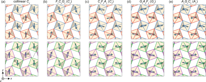
a Schematic illustration of the collinear C-type AFM spin configuration in the two xy planes at (z=frac{1}{2}) (upper panel) and z = 0 (lower panel). The blue arrows represent up and down spin moments of the d orbitals in the TM ions. Here the spins are pointing in the y direction but without SOC their directions can be arbitrarily taken. b The canted AFM structure with major Cy component, compatible with the orthorhombic perovkites under the GdFeO3-type distortion, denoted as FxCyGz (see text); the other canted AFM structures are shown in (c) CxFyAz, (d) GxAyFz, and (e) AxGyCz with major components along the x-axis, Cx, Gx, and Ax, respectively.
Spin current generation and spin-splitting
Now we discuss the altermagnetic characters without SOC (ζ = 0). Figure 5a shows the conductivity of the spin current along the y-axis under an electric field along the x-axis (χxy), obtained by the Boltzmann transport theory and Hartree–Fock (HF) approximation for ({{mathcal{H}}}_{0}+{{mathcal{H}}}_{{rm{int}}}) without the NNN terms, for the (3d)2 case5. It is plotted as a function of the Coulomb interaction U and the BX6 rotation angle ϕ, together with the ground-state phase diagram on the basal plane, choosing model parameters typical of perovskite 3d-TM oxides.
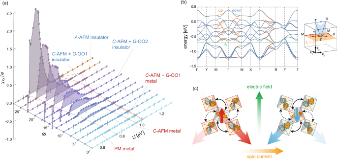
a Spin current conductivity χxy on the U–ϕ plane, for the multi-band Hubbard model without SOC. The black broken lines on the basal plane indicate the phase boundaries between the different phases. The red solid line stands for the MI transition. b Energy band structure of t2g orbitals in the C-AFM metallic phase at (U, ϕ) = (0.725eV, 25°). The Fermi energy is denoted by εf. The right panel shows the symmetric lines in the first Brillouin zone. c A schematic view of the spin current generation in altermagnetic perovskites.
In the absence of the GdFeO3-type distortion (ϕ = 0), with increasing U, successive phase transitions occur from the paramagnetic (PM) metallic phase, the C-AFM metallic phase, and to the C-AFM insulating phase, accompanied by either of the two kinds of G-type orbital ordering [G-OO1 and G-OO2 in Fig. 5a]. Near the transition between the G-OO1 and G-OO2 phases, the system undergoes a MI transition. These C-AFM phases are robust against the increase of ϕ except for ϕ ≳ 25° in the large U region, where the A-type AFM order is stabilized instead. As shown in Fig. 5a, χxy is constantly zero at ϕ = 0, while it turns nonzero in the presence of the GdFeO3-type distortion in the C-AFM metallic phases.
This spin current conductivity is a consequence of the non-relativistic spin splitting in the band structure. The energy band structure in the C-AFM phase is shown in Fig. 5b, for (U, ϕ) = (0.775eV, 25°), where the Fermi energy resides in the t2g bands. One can see the spin splitting in general k-points except for the planes kx = 0, ±0.5 and ky = 0, ±0.5 in the Brillouin zone. This is owing to the TR symmetry breaking by the collinear AFM order and the GdFeO3-type distortion.
In ref. 5, by analyzing the group velocities along the spin-split Fermi surfaces for each spin, it is shown that the up-spin and down-spin electrons have different anisotropies in the directions in which they tend to move, i.e., along the ([1bar{1}0]) and the [110] directions, respectively. As a result of this spin-dependent anisotropy, when an electric field is applied along the [010] direction, the spin current flows along the [100] direction perpendicular to the electric field. These spatial anisotropies originate from the GdFeO3-type distortions as mentioned above [see Fig. 3c, d]. When the up-spin and down-spin occupy different sublattices, i.e., B1 and B2, or, B3 and B4, respectively, owing to the sublattice-dependent anisotropic transfer integrals a finite spin current is induced, whose real-space image is summarized in Fig. 5c.
Let us note the analogy of the spin current generation and the spin splitting here to those first proposed in the organic antiferromagnets κ-(ET)2X8. In κ-(ET)2X, the anisotropic transfer integrals originate from two kinds of molecules (sublattices) in the unit cell with different orientations, playing the role of the ligands with BX6 rotations in perovskites. Since only one molecular orbital per ET molecule plays a role near the Fermi energy in these quasi-two-dimensional compounds, this anisotropy directly results in the d-wave-type spin-splitting in the band structure and explains the mechanism of the spin current generation in a straightforward way. In both cases of the perovskites and the organics, spin current conductivity tensor is symmetric within the xy-plane, χxy = χyx, with vanishing diagonal elements, χxx = χyy = 0, resulting in a peculiar electric-field dependence distinct from the spin Hall effect34,35. Another difference is that the present spin current generation is a dissipative phenomenon as in the electrical conduction; therefore the temperature variation of the spin current conductivity below the Néel temperature is expected to be scaled by that of the longitudinal electrical conductivity.
Anomalous Hall effect
Next, we include the SOC and consider the total Hamiltonian, ({{mathcal{H}}}_{{rm{0}}}+{{mathcal{H}}}_{{rm{int}}}+{{mathcal{H}}}_{{rm{SOC}}}), to discuss the AHE, the condition for its appearance, and its microscopic mechanism6. Within HF approximation to a three-band model for the t2g electrons, similarly to the case without the SOC [Fig. 5a], the C-type AFM states are most stable over a wide parameter range in the (3d)2 case but with the spin directions fixed and not purely collinear as introduced in the section C-type Antiferromagnetic State. The spin pattern is predominantly Cx-type AFM (CxFyAz) [Fig. 4c], with moments mostly oriented along the x-axis when ϕ is small. On the other hand, in the large ϕ region, the Cy-type AFM state (FxCyGz) with the moments mostly along the y-axis becomes stable [Fig. 4b]. For simplification, we will represent each pattern by the major component with the largest projected spin moments, e.g., as Cy pattern. In the following, we focus on the AHE in the Cy phase stabilized in the large ϕ region.
Figure 6a shows the U dependence of the dc Hall conductivity σyz in the Cy phase for ϕ = 25°. Since there is the ferromagnetic component Fx and the AHE appears in the plane perpendicular to its direction, one might recall the case for conventional ferromagnets. However, their magnitude compared to the net moment is exceptionally large. In fact, when we retain only the major component Cy by artificially restricting the mean-field solutions to the collinear Cy order as illustrated in Fig. 4a, the calculated Hall conductivity ({tilde{sigma }}_{yz}), also plotted in Fig. 6a, roughly recovers the original U dependence (it is actually larger than σyz). This trend is also seen in σzx and ({tilde{sigma }}_{zx}) in the Cx phase, where the ferromagnetic moment is parallel to the y-axis. These indicate that the collinear AFM order is essential for the AHE.
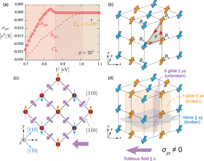
a U dependence of the dc Hall conductivity σyz in the Cy phase for ϕ = 25°. The hatched area is insulating. ({tilde{sigma }}_{yz}) are the results obtained by artificially restricting the mean-fields to the major collinear Cy order. b Schematic view of the Cy-type collinear AFM state, and an example of the triangular path with fictitious magnetic flux θ. c The top view of the magnetic flux distribution in the Cy-type AFM state. The small purple arrows represent the fictitious magnetic fluxes penetrating the square plaquettes on the ((1bar{1}0)) and (110) planes and the large one is the net flux along the –x direction. d The broken/unbroken symmetries in the Cy-type AFM state, resultant fictitious field, and active AHE.
Similarly to the case of spin splitting discussed in the previous section, the AHE vanishes at ϕ = 0, laying out the necessity of the GdFeO3-type distortion. On the other hand, the ϕ dependences of χxy in Fig. 5a and that of σyz in ref. 6 are qualitatively distinct; χxy increases while σyz decreases with increasing ϕ. Furthermore, we should note that the AHE always disappears when we set the NNN terms to zero, even for finite ϕ. These demonstrate the crucial difference between the AHE and the nonrelativistic spin splitting with its resultant spin current generation, since the latter do not require SOC nor the NNN terms. We will discuss their roles from a microscopic viewpoint in the following.
A microscopic interpretation of the AHE by the real space distribution of the fictitious magnetic field acting on conduction electrons provides an intuitive understanding, as discussed in non-collinear magnets such as in the kagome lattice36,37. It is useful in the collinear (or canted) AFM cases as well, as demonstrated first in the case of κ-(ET)2X14, and also in the perovskites6. As shown in Fig. 6b, we take the Cy pattern as an example; now knowing that NNN electron hopping is essential for the AHE, let us consider the smallest triangular paths consists of two NN bonds and one NNN bond (an example is shown in the figure). The magnetic flux θ passing through this triangle ijk is written as (theta =arg ({t}_{ij}{t}_{jk}{t}_{ki})), where tμν (μ, ν = i, j, k) are the transfer integrals between sites μ and ν, which generally become complex numbers due to the SOC and contribute to θ. In each plaquette, there are four possible triangular paths, which cancel out in the paramagnetic state, but do not when the AFM order takes place and provide a finite fictitious magnetic field; the non-equivalent paths with excess up or down spins are responsible for this unbalance. By counting them for all the plaquettes, one obtains a distribution as shown in Fig. 6c, which results, by summing them up, in a net fictitious field along the x-direction and the y component cancels out. Therefore, the electrons moving under an electric field in the yz plane drift perpendicular to both the electric field and the fictitious field, resulting in the AHE.
Finally, we discuss the relationship between the symmetry of the four possible AFM patterns discussed in the section C-type Antiferromagnetic State and the AHE. As mentioned above, there are three independent symmetry operations: a mirror operation perpendicular to the z-axis, a glide operation in the y-direction concerning a plane perpendicular to the x-axis (b glide), and a glide operation in the x + z direction concerning a plane perpendicular to the y-axis (n glide). Table 2 summarizes the relationship between the broken symmetries and the resultant AHE. When two of the three symmetries are broken by AFM ordering, a fictitious magnetic field arises in the direction of the intersection line of these two mirror/glide planes, and an AHE occurs in the plane perpendicular to this direction; in the AxGyCz phase, where all the three symmetries are preserved, the AHE vanishes. This is consistent with the early ab initio study shown in Fig. 2a24. Additionally, this rule is also applicable to the organic altermagnet κ-(ET)2X belonging to the same space group Pbnm, where the AHE discussed in ref. 14 corresponds to GxAyFz in this table. Note that the sx, sy, and sz components that constitute a given AFM pattern shown in Table 2 all have the same symmetry as each other. Taking the FxCyGz as an example, each component Fx, Cy, and Gz breaks the mirror and n glide symmetries even when one of them exists independently, for example, shown in Fig. 6d for the collinear Cy pattern discussed above. Thus, also from the viewpoint of symmetry, the AHE can occur in the presence of a single collinear AFM component, even in the absence of the ferromagnetic net moment.
Candidate materials
Now, we identify potential altermagnetic perovskites where the observations of spin current generation and the AHE are expected, which are seen in a wide range of electron configurations (dn) as summerized in Table 3. As for the spin current generation, CaCrO3, which contains Cr4+ ions with (3d)2 configuration, is one of the plausible candidates. This compound exhibits Cy-type AFM order below 90 K and shows metallic conduction even below the Néel temperature38. The C-type AFM order is also observed in vanadium oxides AVO3 (A = La-Y) with (3d)2 39,40; although this phase is generally insulating accompanied by the G-type OO, this can be suppressed and the system becomes metallic under carrier doping by substitution of the A-site cation41. Furthermore, the spin current generation mechanism discussed here is not limited to d2 systems but can also be applied to systems exhibiting the C-type AFM order with different numbers of d electrons. For example, in d4 systems, similar spin splitting is realized5,26 owing to eg–eg and eg–t2g electron hoppings. This suggests that manganese oxides containing (3d)4 ions and exhibiting the C-type AFM, such as RxA1−xMnO3, could also be potential candidates24,42. Here we focus only on the C-type AFM order in which metallic states have been experimentally observed. However, since the spin splitting occurs also in A– and G-type AFM ordered phases6,26, they could be candidates if they are metallized by carrier doping or proximity effect.
CaCrO3 is also a candidate for the dc AHE, where σyz is expected in the Cy-type AFM metallic phase below 90 K. In fact, the AHE in CaCrO3 has recently been investigated by first-principles calculation by Nguyen et al.43 and indeed shows the dc Hall conductivity in the Cx and Cy phases which are qualitatively consistent with the model calculation6. If we consider the ac AHE, the series of ATiO3 with (3d)1 and AVO3 with (3d)2 are preferred as well. For example, LaTiO3 exhibits the Gx phase accompanied by a complex OO state with distorted TiO6 octahedra44,45 and LaVO3 shows the Cy + G-OO phase shown in Fig. 6a below 140 K, where σyz(ω) at finite ω is expected6. Other typical examples of d3 system are LaCrO3 and YCrO3 containing Cr3+. Either FxCyGz or GxFyAz is indicated in experiments in LaCrO346 and GxFyAz is confirmed in YCrO347,48. Besides, perovskites containing A2+ and Mn4+, such as CaMnO3, and its A-site substitutions, are also possible candidates. For example, Gx-type AFM state is realized in Ca1−xLaxMnO3 with 0 ≤ x < 0.07 49,50,51 and Ca1−xSrxMnO3 with 0 ≤ x < 0.5 52,53, and Gz-type AFM is realized in Ca1−xCexMnO3 with 0.025 ≤ x < 0.075 54; their mother compound LaMnO3 with d4 configuration showing the Ay-type AFM is also a canditate55,56. Furthermore, LaFeO3 and YFeO3, along with other rare-earth based compounds, which are (3d)5 systems containing Fe3+, also exhibit Gx-type AFM state24,56,57,58,59. Not only oxides but also fluorides, such as NaMnF360 and KMnF361,62,63, are promising candidates.
Summary and perspectives
In summary, we have reviewed theoretical studies on altermagnetic properties in perovskites. The spin splitting in the antiferromagnetic ordered phase pointed out in the early first-principles calculations is reproduced by the multi-d-orbtial Hubbard model analysis. The microscopic origin is a cooperative effect of the antiferromagnetic ordering and the spatially anisotropic inter-orbital electron hoppings that depend on the sublattices caused by the GdFeO3-type lattice distortion. This spin splitting gives rise to the spin current generation characterized by the symmetric conductivity tensor under an external electic field in the antiferromagnetic metallic phase. Besides, when the relativistic spin-orbit coupling is introduced, the anomalous Hall effect emerges in the canted antiferromagnetic phase, where the next-nearest-neighbor transfer integrals as well as the nearest-neighbor ones play an important role for generating the net fictitious magnetic field. Although the anomalous Hall effect appears in the plane perpendicular to the weak ferromagnetic moment, the essence is the collinear antiferromagnetic component on the GdFeO3 structure that has the same symmetry with the ferromagnetism.
Researches on altermagnetism is now explosively expanding, represented by the direct observations of the spin-split bands64,65. Other cross-correlation phenomena are discussed, such as piezomagnetic effect66, cooperative effects with superconductivities67, and topological insulators68, which lead us to expect further discovery of novel phenomena in the future. For example, recently an AHE originating from the proximity effect at the interface between two kinds of distorted perovskites, showing a paramagnetic metal and an AFM insulating phases, has been experimentally observed69. This might be interpreted as a cooperative effect of the present altermagnetic AHE and the so-called topological Hall effect owing to the scaler spin chirality36, which is an interesting issue awaiting further theoretical analysis.
Perovskites have been synthesized in various forms and numerous antiferromagnetic ordered phases have been studied. In contrast, Table 3 gives only a partial and non-exhaustive list of representative ABX3 systems with B taking 3d-TM elements, and therefore many other compounds not included here, such as Ruddlesden–Popper-type An+1BnX3n+1, and 4d and 5d perovskites, can also be promising candidates for altermagnetic perovskites. Reexamination and reconsideration of their electronic states are crucial for exploring highly functional altermagnets, and further experimental studies in this field are greatly anticipated. Let us conclude this article hoping that the series of research will pave the way to the realization of “interesting and applicable antiferromagnets” beyond Néel’s prediction.


Responses