Anisotropic magnetoresistance in altermagnetic MnTe

Introduction
Recently, collinear magnets were classified by spin-group symmetry into three distinct classes. In addition to the conventional ferromagnets and antiferromagnets a third class, altermagnets, was established1,2. In this third group of collinear magnets, a compensated magnetic order has opposite magnetic sublattices solely connected by real space rotation possibly combined with translation or inversion transformation3. In contrast, conventional ferromagnets have only one spin sublattice or opposite sublattices not connected by any symmetry transformation, and conventional antiferromagnets have opposite sublattices connected by translation or inversion. These distinct symmetry properties reflect in the physical properties of these magnetic materials. In the limit of vanishing relativistic spin-orbit coupling, antiferromagnets show spin degenerate bands while ferromagnets and altermagnets can host spin polarized bands. In altermagnets, the spin split band structure is furthermore connected to the rotation symmetry linking the magnetic sublattices. Angle-resolved photoemission experiments identified various altermagnetic compounds, among them MnTe, CrSb, and RuO24,5,6,7,8. Hints on altermagnetism in these materials were previously also already obtained by the presence of an anomalous contribution to the transverse magnetoresistance9,10,11,12,13,14 as well as the detection of a spontaneous X-ray magnetic circular dichroism15. In addition to the anomalous transport contributions, altermagnets, as all magnetically ordered materials, host anisotropic magnetoresistance (AMR), i.e., a change of the symmetric components of the resistivity tensor (even under time reversal) upon a directional change of the magnetic order vector16,17. The AMR is distinguished into non-crystalline and crystalline AMR contributions. The noncrystalline contribution is found in all magnetically ordered systems and shows a twofold dependence of the angle between the current and magnetic order vector17, which in our system is the Néel vector. In systems with high crystalline quality, additional higher-order contributions appear, called crystalline AMR17. Since these contributions are linked to crystalline symmetry, a symmetry analysis can reveal which terms to the AMR are in principle allowed and forbidden. While such analysis establishes a general framework, predicting the strength of individual components is more difficult: Explanation attempts for the strength of two- and fourfold components have been made for cubic and tetragonal systems18, for hexagonal systems they are missing to date. Usually, it is observed that the dominant higher-order contribution in cubic and tetragonal systems is fourfold19,20, while it is sixfold for hexagonal systems21,22,23. Furthermore, it must be noted that experimental data are usually tracked against the rotation of the magnetic field instead of the magnetic order vector, for convenience reasons. In such signal, there will be an interference of magneto-crystalline anisotropy and AMR, which itself might cause higher-order terms and need to be unraveled. A more comprehensive overview of the topic of AMR can be found in ref. 17. In MnTe, AMR was previously used to demonstrate that by field cooling with magnetic field in various orientations, the remanent resistance of the material can be influenced22. MnTe is a particularly interesting member of the class of altermagnets24 since it is a semiconductor with a band gap of ~1.4 eV22,25,26, and can be doped to host both electron and hole-dominated transport27. Therefore, MnTe enables transport of spin-polarized currents in semiconductors28. Neutron diffraction and AMR were previously used to determine the magnetic structure and anisotropy of the material23,26,29,30 (Note that our previous work22,23 concerned the same magnetic structure and we now classify MnTe according to ref. 3 as an altermagnet.) In MnTe, the magnetic anisotropy was found to be such that the antiparallel magnetic moments align within the hexagonal basal plane. In undoped MnTe, the magnetic moments can be manipulated in the basal plane by magnetic field22,23,31, suggesting that the anisotropy barrier in the basal plane is significantly smaller than the out-of-plane anisotropy. Additionally, the magnetic anisotropy can be altered by doping32 and the influence of the magnetic moment orientation on the electronic structure was studied by first-principle calculations33,34.
In this work, we study experimentally how the Néel vector can be manipulated by the application of a magnetic field within the basal plane and how the electrical resistivity of the material changes accordingly. We establish which angle-dependent components of the magnetoresistance anisotropies are expected in MnTe from symmetry analysis. We further experimentally study the angle-dependent variation of the resistivity under the application of magnetic field and extract the various components with respect to the field angle, and establish their functional dependence on the current and crystal direction. Stoner Wohlfarth modeling35 is used to discuss the magnetic field dependence.
Results
Symmetry analysis of the magnetotransport response
α-MnTe crystallizes in the hexagonal NiAs structure (crystallographic space group P63/mmc #194, ref. 36) depicted in Fig. 1a. The magnetic moments of the two Mn atoms in the unit cell align antiparallel within the c-plane/basal plane of the material with a preferential easy axis alignment along the ([01bar{1}0]) or the other two equivalent crystal directions (magnetic space group (C{m}^{{prime} }{c}^{{prime} }m)13,23). The magnetic anisotropy identified in previous studies23 showed that the magnetocrystalline anisotropy barrier within the basal plane is smaller as compared to the energetic difference for an c-axis orientation of the Néel vector. We therefore limit our symmetry analysis of the resistivity tensor ρij, performed with the tool “symmetr”37, to a rotation of the Néel vector within the basal plane. Due to the thin film geometry we furthermore limit the electrical current to the basal plane. The coordinate system is chosen as x and y along ([2bar{1}bar{1}0]) and ([01bar{1}0]), respectively (Note that we use Bravais indices hkil, with i = −h −k for the hexagonal MnTe, while Miller indices hkl are used for the cubic substrate.). Table 1 lists the resulting components of the longitudinal and transverse resistivities in dependence of the current and Néel vector orientation, considering terms up to 6-th order in the Néel vector angle. The twofold term in the longitudinal resistivity, depending on the relative orientation of the Néel vector with respect to the current, corresponds to the non-crystalline AMR commonly found in all magnetically ordered materials, i.e., even in polycrystalline ones. Furthermore, we find that for the longitudinal resistivity, also higher even order terms are allowed due to crystalline symmetry. In contrast, the transverse resistivity ρ⊥ contains odd terms in addition to the even AMR (or sometimes called planar Hall effect) terms. Here in particular, a threefold term corresponds to the anomalous Hall effect, i.e., to the antisymmetric off-diagonal component of the resistivity tensor, present due to the altermagnetic nature of the material13,14.

a Depiction of the crystal and easy axis configuration of the α-MnTe structure. b X-ray diffraction pole figure measurement of the MnTe (1bar{1}02) Bragg diffraction shown in stereo-graphic projection. Red circles mark the expected diffraction positions of single crystalline MnTe. c SQUID magnetometry data of the MnTe/InP sample for in-plane magnetic field at T = 50 K. To emphasize the lack of residual magnetization, we subtracted a linear slope near zero magnetic field from the data shown in the inset. It is important to note that the subtracted slope encompasses both the susceptibility of MnTe and the diamagnetic substrate as detailed in the methods section. The dashed lines indicate the spin-flop field of ~3 T. d Microscopy image of a lithographically processed Hall bar as well as a sketch of the employed electrical schematic, coordinate system and definition of the magnetic field geometry for angle-dependent resistivity measurements.
Sample characterization and fabrication
To experimentally test the existence of these terms, we employ magneto transport experiments in single crystalline MnTe thin films grown by molecular epitaxy with a typical thickness of 35 nm. The hexagonal structure of these films is evident from the X-ray diffraction pole figure measurement presented in Fig. 1b showing a sixfold symmetric signal at the expected positions. In-plane magnetometry measurements in Fig. 1c show the dominant diamagnetic signal of the substrate with no detected spontaneous magnetization consistent with the compensated magnetic structure depicted in panel (a)13,23. After subtraction of a linear contribution, remaining features in the magnetometry data indicate a change of the susceptibility around ~3 T which is related to the reorientation of the magnetic order (spin-flop). Additionally, the very small step-like signal is most probably related to a magnetic impurity which is commonly found in commercial substrates and it has no correspondence to the magnetotransport data.
The films provide the ideal platform to study magnetotransport within the basal plane. For this purpose, we pattern Hall bar structures with various in-plane orientations. Electrical transport is enabled by intrinsic p-type conductivity commonly observed in nominally undoped MnTe26,27,38.
Magneto-transport
For our measurements, we mainly employ angular-dependent magnetoresistance (ADMR) measurements, where we rotate an in-plane magnetic field and track the corresponding resistivity change. Note that, this is apriori different from AMR where the dependence of the resistivity on the angle of the magnetic moments is considered (and moreover, symmetry requirements on the response are imposed), which is why we will use these two expressions distinctly in this manuscript. The magnetic field angle α is defined between the x-axis, i.e., 90° rotated from one of the magnetic easy axes, and the direction of the applied magnetic field in the sample plane as shown in Fig. 1d. Figure 2 shows ADMR measurements of the longitudinal resistivities ρxx and ρyy as well as transverse resistivities ρ⊥,x and ρ⊥,y for current along x and y direction, respectively. While we show only the data for clockwise rotation of the magnetic field in Fig. 2, both rotation data are shown in the Supplementary Fig. 1. For strong fields, i.e., 8 T, a clear harmonic variation of the resistivity with α is observed which is distinct for longitudinal and transverse resistivity as well as for the different current directions.
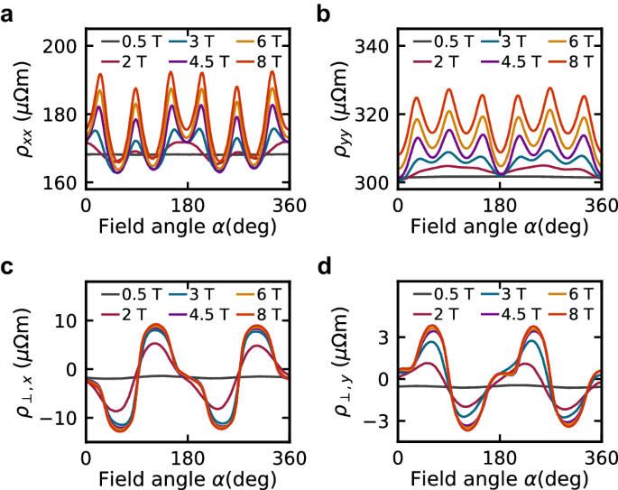
a, c Longitudinal and transverse resistivity for a Hall bar along the x-direction. b, d Same for the y-direction. Selected measurements from the probed magnetic field range up to 8 T are shown. Note that here, only the clockwise field rotation data are shown for clarity.
Fourier component analysis
To understand our experimental results, we perform a Fourier component analysis, where we separate the experimental data into a sum of ({A}_{n}cos (nalpha +{alpha }_{n})) terms. An, αn corresponds to the amplitude and phase offset of the n-th component with respect to the magnetic field angle, respectively. The An values should not be confused with ρ(n) in Table 1, since ρ(n) refers to angle θ rather than α. Figure 3a shows that in the longitudinal signal, the amplitudes of the components of the order 2, 4 and 6 dominate the signal. Additionally, a weaker but clearly detectable signal is present for n = 12, which will be discussed further below. In Fig. 3b, we find in the transverse resistivity only clear signals for n = 2, and 4. Figure 3c, d shows how the strong contributions with a phase offset near 0 or π for the longitudinal resistivity exhibit cosine-like behavior, and the ones with a phase offset near ±π/2 for the transverse resistivity exhibit a sine-like behavior. These patterns align with predictions from the symmetry analysis summarized in Table 1 which is also consistent with earlier measurements on Corbino devices23. The symmetry analysis further implies that, the absolute values of the amplitudes of the twofold and fourfold components must be equivalent for the longitudinal or transverse resistivity. The sign of the fourfold component, however, should flip between the longitudinal and transverse resistivity. Figure 3a, b shows consistent amplitudes for n = 2, and 4. However, while both components have a phase near−π for the longitudinal data, the transverse data shows a phase of ~π/2 for n = 2 and −π/2 for n = 4, confirming a difference in sign.
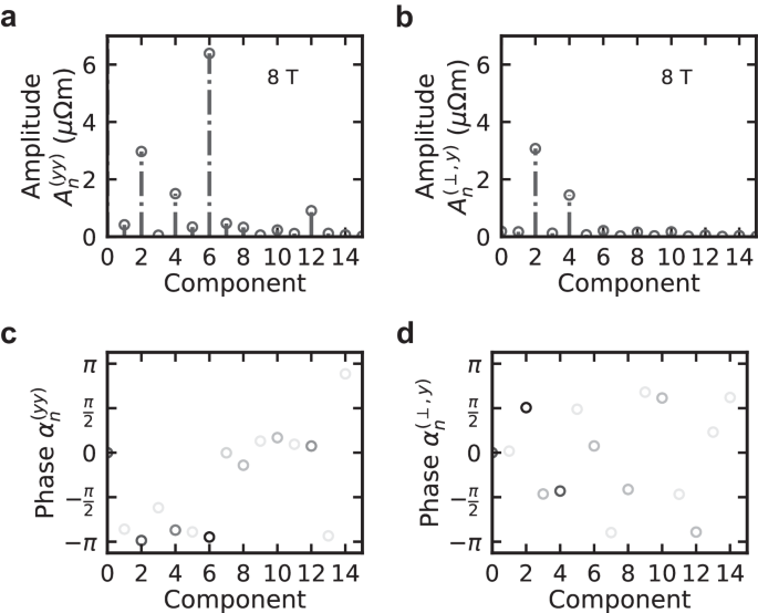
a–d Amplitudes and phase offsets of the frequency components for the longitudinal resistivity and transverse resistivity signals for current along y, respectively. The analysis is shown for the data set recorded at magnetic field of 8 T shown in Fig. 2b, d.
Comparing the component analysis of the ADMR data for currents along y and x directions (c.f. Supplementary Fig. 2) we are able to check the functional dependence of the components on the current direction. In particular, we can identify which terms depend solely on the relative orientation of the magnetic moments and the crystal direction. We find the phase of the sixfold term effectively unchanged (change by ~2π) indicating that this term depends on the orientation of magnetic moments and the crystal direction consistent with Table 1. In contrast, the phase of the twofold and fourfold terms is changing by ~π, i.e., equal to twice the rotation of the current direction, which is again what we obtain from our symmetry analysis. Note that here we assume that for sufficient field amplitude, the magnetic moments rotate with the field which we verify below.
What makes altermagnets different to ({mathcal{PT}})-symmetric collinear antiferromagnets is the possible presence of the anomalous Hall effect. The threefold component in Table 1 would be forbidden in ({mathcal{PT}})-symmetric collinear antiferromagnets and its presence, in turn, is characteristic of an altermagnet. Figure 4 displays the residual signal after subtracting the even-in-field contribution from our ADMR data. It shows that among the odd-in-field terms, the threefold contribution (due to the anomalous Hall effect) is dominant. In our experiments, this component is weak since an in-plane magnetic field is unable to set the polarity of the Néel vector and therefore, the two opposite polarities causing an opposite sign of the anomalous Hall effect, are simultaneously present and keep the threefold component small13. The magnetic field dependence of the threefold component (shown in Supplementary Fig. 3) shows a saturation behavior at the spin-flop field, suggesting the presence of a certain imbalance of Néel vector polarities. If this imbalance is resulting from an unintentional out of plane magnetic field component or is present apriori needs further investigation. However, when measured with a polarizing out of plane magnetic field the anomalous Hall effect strength can be significantly increased13. In the following, we will again focus on the even terms due to AMR, which dominate the magnetotransport for in-plane magnetic fields.
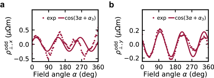
a, b Odd contributions to ρ⊥,x and ρ⊥,y obtained after subtraction of the dominating even-in-field contribution from raw data at 2 T shown in Fig. 2c, d. The even-in-field contribution was determined by fitting ({sum }_{n = 2,4,6,8,10}{A}_{n}cos (nalpha +{alpha }_{n})). The odd component is dominated by a threefold symmetry which is highlighted by the continuous line representing a guide to the eye proportional to ({A}_{3}cos (3alpha +{alpha }_{3})).
We now use the Fourier analysis introduced above in order to determine the magnetic field dependence of the various components. We show in Fig. 5a, b (and Supplementary Fig. 4) the field dependence of the amplitude of all even components of the longitudinal and transverse resistivities corresponding to the data shown in Fig. 2 for current along y (x). For both of these data sets we observe a gradual onset of the various amplitudes with a saturation tendency for fields above ~3 T. This suggests that above this amplitude the magnetic field is strong enough to induce a full rotation of the magnetic moments. Consistent with our previous analysis we find amplitudes and field dependence of the twofold and fourfold contributions to correspond to each other when comparing longitudinal and transverse data. The sixfold contribution is detected only in the longitudinal resistivity and shows a somewhat distinct field dependence which either saturates only at higher fields or even has a contribution which does not saturate in the explored field range. In the right panel of Fig. 5a, we focus on the higher order even components of the longitudinal resistivity. In particular, we find the twelvefold component to have a field dependence similar to the one found for the sixfold one. It is, however, unclear if the twelvefold component is indeed a distinct component or the result of a sixfold anisotropy contribution which causes the magnetic moments to deviate from the direction dictated by the magnetic field.
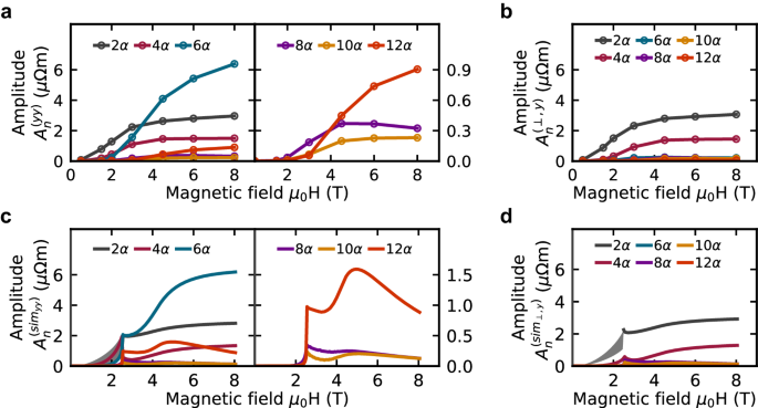
a, c, and b, d Variation of the amplitudes of the even order components of the longitudinal resistivity and transverse resistivity for current along y, respectively. Right panels in (a, c) show an enlarged view of the variation of the high order even contribution of the longitudinal resistivity. While (a, b) show experimental data, (c, d) show the data extracted from our modeling.
Stoner Wohlfarth modeling
To obtain a better understanding of the field dependence and presence of different components, we set up a Stoner Wohlfarth model17,35 in which we assume a harmonic hexagonal anisotropy and limit the magnetic moments to the basal plane. For a given magnetic field direction and amplitude we minimize the energy with respect to the magnetic moment orientation and thus effectively obtain the history-dependent function θ of α. Using this moment orientation and the AMR components determined by our symmetry analysis we mimic our magnetotransport data. We find that the magnetic moments remain nearly antiparallel and, under strong magnetic field, tend to align almost perpendicular to the applied magnetic field, regardless of the in-plane field direction. Therefore, we use solely the Néel vector orientation and ignore the small induced uncompensated moment in our analysis. The resulting calculated anisotropic resistivity data are then plugged into our Fourier component analysis. The field dependent amplitudes of these modeled data are shown in Fig. 5c, d. Note that we used the strength of the anisotropy and saturation amplitudes of the AMR components to obtain a field dependence similar to the experiments. Since the Stoner Wohlfarth model considers a single-domain situation the modeling results are not unique for small fields. Depending on the relative orientation of the initially populated easy axis, a range of results can be obtained for magnetic fields below the spin-flop field. For higher field amplitudes, the moment’s orientation is unique and does not depend on the starting conditions. The spin-flop transition causes a very sudden change in the model since no variation of the anisotropy barrier, domain wall pinning or thermal excitations are considered. It is furthermore noteworthy, that we plug into our model only AMR terms from Table 1, but we find also higher components with n > 6 in the Fourier analysis. Higher order components in the model arise from the deviation of the Néel vector orientation from the direction perpendicular to the magnetic field, which are caused by the magnetocrystalline anisotropy. The competition between the anisotropy energy and the Zeeman energy leads to a complex dependence of these components on the magnetic field strength. Our model calculations suggest that with stronger magnetic field, i.e., when the magnetocrystalline anisotropy energy gets relatively less important, the higher-order components decay. In particular, we show in Fig. 5c, d the magnetic field dependence of contributions with n = 8, 10, and 12. Supplementary Fig. 5 shows the detailed frequency and phase analysis of the modeling data which capture the same features as observed in the experiments.
High field and temperature-dependent magnetotransport
In order to clarify the magnetic field dependence of the higher-order components, we performed a second set of experiments. Here we focus on the variation of the longitudinal resistivity in a separate thin film sample and used magnetic field up to 14 T. Figure 6a shows the measured data, while the resulting field-dependent variation of the Fourier components is shown in Fig. 6b. Consistent with our previous experiments, we do find the terms with n = 2, 4, 6, and 12 to dominate in the data. For this field range, our model suggests a visible decay of the twelvefold component, but no such decay is detected in the experiments—only a saturation behavior is observed.
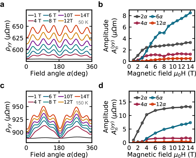
a Selected raw data for a Hall bar along y direction, recorded at T = 50 K. b Magnetic field dependence of the dominating frequency components at T = 50 K. c Selected raw data for a Hall bar along y direction, recorded at T = 150 K. d Magnetic field dependence of the dominant frequency components at T = 150 K. Note that data in (a, c) are shown as measured and no vertical offset was added between the curves.
In Fig. 6a, in addition to the AMR also a field-dependent isotropic magnetoresistance contribution can be observed. This can be extracted from our analysis as the term n = 0 and is shown in Supplementary Fig. 6. We find an isotropic positive magnetoresistance of ~10% at a magnetic field of 14 T. Both the isotropic magnetoresistance and relative strength of the AMR components are changing with temperature. For ADMR measurements and analysis performed at a temperature of 150 K shown in Fig. 6c, d, we find the shape of the data is noticeably different. This is caused by a change in the weights of the various AMR components. In particular, we find that at increased temperature the twofold non-crystalline AMR term dominates and the four and sixfold ones are relatively weaker. The magnetic field dependence of the non-crystalline AMR remains similar and saturates for high fields, while the sixfold term similar to the 50 K case shows no saturation.
Discussion
Our analysis of the angle-dependent magnetotransport in altermagnetic MnTe reveals that there are various regimes of magnetic field strength which need to be considered somewhat separately. These are: (i) weak fields, i.e., below the spin flop transition, (ii) intermediate fields, i.e., just above the spin flop transition, (iii) strong fields aligning all moments along the field. In the weak fields the magnetic order is not fully rotated upon a magnetic field rotation, instead, it only slightly wiggles around the magnetic easy axis/axes. In this field regime, it is crucial to distinguish the angle of magnetic field in ADMR measurements from the angle of the magnetic moments governing the AMR. In this regime, also the population of multiple easy axes domains may play a crucial role. For compensated magnets, the field strength needed to overcome this regime (often called spin-flop field) can greatly vary. While in the canted antiferromagnet Sr2IrO4 a few 100 mT are sufficient39,40, in near easy plane systems like Fe2As 41 and MnTe several Tesla are required. In other systems like CrSb2, no sign of saturation of the ADMR signal could be observed up to 24 T42. Once the required characteristic field to rotate the compensated moments is overcome, i.e., for intermediate field strength, the magnetic moments can fully rotate coupled with the magnetic field. Nevertheless, a distinction of ADMR and AMR is still necessary. The compensated moments tend to align nearly antiparallel and almost perpendicular to the magnetic field, merely with a minimal canting of the moments towards the magnetic field and angular offsets determined by the competition of anisotropy and Zeeman energy. In this regime, a near saturation of the ADMR variation can be observed in Fe2As 41. In MnTe, we also observe a saturation tendency, in particular of the components with two-, and four-fold symmetry. However, the component with sixfold symmetry continues to increase up to the maximum applied field of 14 T. It is conceivable that some ADMR components in compensated magnets saturate only under full saturation, i.e., for the highest magnetic fields, corresponding effectively to a parallel arrangement of the moments. Experimentally, this is typically reachable only for specially tuned anisotropies43, but otherwise, commonly beyond the experimentally available magnetic field strength. For increasing magnetic field, a continuous transition occurs between the canted rotation of the Néel order, regime (ii), and the full saturation, regime (iii). Often, in this regime, the magnetization induced by the magnetic field can not be ignored anymore. This might contribute to the lack of saturation of the sixfold ADMR component in MnTe. In our magnetoresistance modeling, a contribution of the induced magnetization resulting from the canting of the magnetic moments is ignored. Nevertheless, connected to the sixfold AMR combined with the sixfold anisotropy within the basal plane, our Stoner Wohlfarth model also reproduced the experimentally detected component with twelvefold symmetry. Whether there is indeed such an intrinsic AMR component with twelvefold symmetry present in MnTe, or our assumed Stoner-Wohlfarth model is too simple, is presently unclear. Future experiments at even higher fields might be able to clarify this. Theoretical efforts to explore the exact shape of the anisotropy, its microscopic origin44, and the impact of the moment orientation on the electronic structure are needed to develop a more precise model.
In conclusion, we have shown the angular dependence of the magnetoresistance in altermagnetic MnTe. While previous studies focused on the anomalous Hall effect or on magnetoresistance variation after field cooling, we show here that under an in-plane applied magnetic field, MnTe exhibits various anisotropic magnetoresistance contributions. In particular, we have identified both by theoretical symmetry analysis and magnetotransport experiments that harmonic variations of the resistance related to the in-plane orientation of the Néel vector are present in MnTe. Application of magnetic fields above ~3 T can induce a full rotation of the magnetic moments and experiments performed for different current directions allow us to confirm the functional dependence on current and moment direction. The implementation of a Stoner Wohlfarth model provides a valuable framework for clarifying the field dependence and presence of different components. At low temperature, the component with sixfold symmetry, related to the sixfold crystalline symmetry, dominates the magnetotransport. The more commonly observed non-crystalline AMR with twofold symmetry becomes dominant at higher temperatures. In the experiments, we furthermore identified also higher-order components which are also reproduced by model calculations. Their exact microscopic origin, however, remains elusive and more studies, at high magnetic fields and more first principle studies are needed. Altermagnetism manifests itself in the magnetotransport as a threefold anisotropic contribution to the transverse magnetoresistance due to the anomalous Hall effect. Our work contributes to the understanding of the magnetotransport properties of MnTe which is evolving as a workhorse material for altermagnetic spintronics.
Methods
Symmetry analysis of the resistivity tensor
The procedure used for analyzing the symmetry of the resistivity tensor is similar to the one discussed in ref. 45 for spin–orbit torque. We start by expanding the resistivity tensor ρij in the Néel vector L:
The symmetry of this expansion is determined by the non-magnetic symmetry of the crystal because the non-magnetic symmetries relate the resistivity tensors for different L orientations. For each symmetry operation, we have to determine how the expansion terms transform. The first two indices correspond to the resistivity tensor itself and thus, transform the same as the resistivity tensor. The transformation of the other indices is determined by the transformation of the Néel vector. We note that the Néel vector does not transform the same as magnetization, since in MnTe there are symmetry operations that interchange the sublattices and thus change the sign of the Néel vector. This also means that the transformation of the Néel vector cannot be determined just from the non-magnetic space group, but requires keeping track of how the non-magnetic symmetry operations permute the magnetic sublattices. We also impose the constraint that the expansion tensors are invariant under interchanging any two indices corresponding to the L vector (i.e., kl…), as well as the Onsager relations which state that the ({mathcal{T}})-even component of the resistivity tensor is symmetric and the ({mathcal{T}})-odd component is anti-symmetric.
For each symmetry operation, it must hold that the transformed expansion tensor is equal to the resistivity tensor. This forms a set of linear equations for the components of the resistivity tensor. These equations either have only null solution, in which case the expansion tensor ({rho }_{ijk}^{(i)}) vanishes or it has infinitely many solutions. In such a case the dimension of the vector space of solutions determines the number of the free parameters of the expansion tensor. To solve the system of linear equations we use the SVD decomposition. We then use Gaussian elimination to eliminate the dependent variables. This is repeated for every symmetry operation. We have implemented this whole procedure in open-source code Symmetr37.
Since the anisotropy of our MnTe limits L to the ab plane we use ({bf{L}}/L=(cos (theta ),sin (theta ),0)), where θ denotes the angle between the x-axis and L. Substituting this for L we obtain an expansion in powers of (cos (theta )) and (sin (theta )). This can be converted to expansion in (cos (ntheta )) and (sin (ntheta )), where n are integers. Note that in general terms of n-th order in the powers of (cos (theta )) and (sin (theta )) expansion correspond to n-th and lower order terms in the (cos (ntheta )) and (sin (ntheta )) expansion. Writing down the current as ({bf{j}}=(cos (varphi ),sin (varphi ),0)), considering terms up to sixth order, and separating the components parallel and perpendicular to current, we obtain the results in Table 1.
Thin film growth and characterization
The single crystalline epitaxial α-MnTe thin films are grown by molecular beam epitaxy (MBE) on InP (111)A substrates. A two-dimensional growth of MnTe, as judged by streaked RHEED pattern, is achieved at substrate temperatures in the range of 370 °C-450 °C. The samples studied here have a thickness of 48 nm and 35 nm. For structural characterization we carried out X-ray diffraction radial scans as well as pole figure measurements with CuKα1 radiation. The orientation of our layers on the substrate is ((0001){[1bar{1}00]}_{{rm{MnTe}}}| | (111){[11bar{2}]}_{{rm{InP}}}), i.e., c-axis is the out-of-plane direction and the hexagonal basel plane is inside the sample plane. SQUID magnetometry, with magnetic field in the basal plane, was used to study the magnetic properties of the samples. To highlight the spin-flop transition, we subtract a linear background which contains contributions from the substrate, the sample holder and the MnTe thin film. The subtracted slope was chosen in a way to obtain a flat region below the spin flop field. This procedure means that we underestimate the field-induced magnetization of the MnTe.
Lithographic processing of Hall bars
Hall bars were fabricated in different orientations on our MnTe thin films. For the patterning, we used electron beam lithography, argon-based ion beam etching or argon ion milling in a plasma etcher, and electron beam evaporation of Cr/Au contacts. Data in Fig. 2a, c are from two different Hall bars along the x direction (([2bar{1}bar{1}0])) with a width of 50 μm and longitudinal contacts spaced 500 μm apart, and width of 30 μm and longitudinal contacts spaced 300 μm apart, respectively. Data in Fig. 2b, d and Fig. 6 are from two separate Hall bars oriented along the y direction (([01bar{1}0])) with a width of 30 μm, and the longitudinal contacts are positioned 300 μm apart. Data in Fig. 2 and Fig. 6 are from different thin films.
Measurement setup
The magneto-transport measurements were performed using two different setups. The first setup utilizes a Quantum Design Physical Property Measurement System (PPMS) with in-built electrical transport option (ETO) and sample holder (PCB 7084) allowing for in-plane field rotations. It comprises a precision current source and voltage pre-amplifiers coupled to a digital signal processing (DSP) unit. A sinusoidal AC drive current is applied. The DSP unit is then used to record the voltage response and filter the portion of the signal at the same frequency as the drive current. Typical frequency and current amplitude used were 18.3 Hz and 0.01 mA, respectively, which corresponds to ~5 × 10⁶ A/m2. Experiments described in “Magneto-transport” and “Fourier component analysis” were performed using this setup.
For experiments described in Results, “High field and temperature dependent magnetotransport”, a higher magnetic field capacity of up to 14 T was used. Although the same measurement procedure was followed, an alternating current using a Keithley 6221 AC current source was applied and a Zurich MFLI lock-in amplifier 500 kHz–5 MHz was used to record the data.
In both cases, the samples were electrically contacted by wedge bonding, and BNC and RCA electrical connectors were used. The sample temperature was sufficiently stabilized before the ADMR data were recorded by a step-wise rotation of the sample in a constant magnetic field, i.e., during the data acquisition no movement or field sweeps were performed. The samples were rotated both in clockwise and anticlockwise fashion.
For magnetotransport measurements with current along the x-axis, the contact configuration depicted in Fig. 1d was rotated by 90°. This includes the polarity of the transverse voltage detection which leads to the fact that ρ⊥,x corresponds to ρyx, and ρ⊥,y to ({rho }_{bar{x}y}), where (bar{x}) indicates the change in the polarity. Employing this nomenclature allows for a direct comparison with the data in Table 1.
Fourier component analysis
To analyze our data we perform a discrete Fourier transform of the angular-dependent magnetoresistance data. The resulting complex frequency components are converted to their respective amplitude and phase values. This means we effectively decompose our signal as follows:
where An represents the amplitude of the n-th component, α represents the angle at which the magnetic field is applied with respect to the x axis (([2bar{1}bar{1}0])), and αn the phase offset of the n-th component. We analyze the amplitude and phase spectrum and focus on the initial 15 components since we find components with n > 15 to be negligible.
Stoner Wohlfarth model of MnTe
The equilibrium orientation of magnetic moments in MnTe was determined by considering a sixfold magnetocrystalline anisotropy, exchange energy, and Zeeman energy within a single-domain model. For the total energy E per sample volume V we use:
where Jex is the exchange constant, EMAE is the magneto-crystalline anisotropy function, Mi are the sublattice magnetizations, and B is the magnetic field. A hat (” (hat{phantom{1}}) ”) denotes a unit vector. We restrict ourselves to a 2D description within the basal plane, which is sufficient to describe our in-plane magnetic field rotations. Within the basal plane we use the easy axis orientation (one of the (< 01bar{1}0 >) directions) as our reference direction and define the angle of the magnetic field α and the angle of the magnetic moments (ψ1, ψ2) of the sublattice with respect to this axis. Inserting the angular positions of the sublattices, magnetic field, and the exchange field defined as Bex = Jex/M with (M=leftvert {{bf{M}}}_{1,2}rightvert) this can be rewritten as
The exchange field is estimated from the Néel temperature as Bex = kBTN/μB, where we use the Boltzmann constant kB and the Bohr magneton μB. The magneto-crystalline anisotropy energy density is expressed as
following from the sixfold in-plane symmetry of the hexagonal material. Here, KMAE has units of energy density and is used as a free parameter. It is chosen such that a resulting spin-flop field of ~2.5 T is obtained in the model. From a numerical minimization using the conjugate gradient method we obtain the orientations of the magnetic moments (ψ1, ψ2). Using the resulting Néel vector orientation, given by the angle φ = (ψ1 + ψ2 − π)/2, we calculate the contribution to the anisotropic magnetoresistance as given in Table 1.


Responses