Antiferromagnetic order of topological orbital moments in atomic-scale skyrmion lattices
Introduction
Magnetic skyrmions have raised widespread attention because of their fascinating topological and dynamical properties1,2. Due to the spin topology of a skyrmion an emergent magnetic field arises which causes the topological Hall effect3 allowing electrical detection of single skyrmions4. Another key consequence of electron motion in the fictitious magnetic field is the topological orbital moment. It can occur in non-coplanar spin structures even in the absence of spin-orbit coupling and depends on the local scalar spin chirality3,5,6,7. The scalar spin chirality is proportional to the topological charge density and can serve as a measure of topological transport properties3,5,6,8.
Topological orbital moments have been predicted for several types of spin structures such as multi-Q states5,9, atomic-scale spin lattices8, and isolated skyrmions6,10. In the triple-Q state11,12,13—exhibiting tetrahedron angles between adjacent spins on a hexagonal lattice and a net vanishing spin moment—the topological orbital moments align such that a net orbital magnetization remains5. Such topological orbital ferromagnetism has also been proposed for the bulk antiferromagnet γ-FeMn14. A net topological orbital moment remains as well for single skyrmions in a ferromagnetic background and it has been suggested that these are observable via XMCD6. The orbital magnetization can be manipulated by an external magnetic field which has been shown via the spontaneous topological Hall effect in the triple-Q state15,16. Other prime candidates for the investigation of topological orbital moments are zero-field non-coplanar magnetic states that have been experimentally found in Fe monolayers in contact with a hexagonal Ir film17,18. Due to the large tilting angles between adjacent spin moments such spin textures could result in significant topological orbital moments. Designing appropriate nano-scale non-collinear spin structures and harnessing their orbital moment may be of great benefit in spintronic applications19,20.
Here, we investigate the non-coplanar spin structure of Fe/Ir-3/Re(0001) using SP-STM experiments with different tip magnetization directions as well as DFT calculations and an atomistic spin model. We show via DFT that multi-Q states and atomic-scale skyrmionic lattices constructed based on the experimentally determined magnetic unit cell are energetically significantly favored with respect to all single-Q (spin spiral) states due to higher order interactions. Indeed, comparison of measured and simulated SP-STM images indicate the presence of an atomic-scale skyrmion lattice. The superposition states are stabilized by the four-site four spin interaction as shown via mapping DFT total energies to an atomistic spin model. Due to their non-coplanar spin textures significant local topological orbital moments arise in these multi-Q states and atomic-scale skyrmionic lattices. Intriguingly, these considered spin structures exhibit antiferromagnetic order of the arising topological orbital moments.
Results
SP-STM experiments
Pseudomorphic Fe monolayers on Ir ultra-thin films on Re(0001) have been investigated experimentally before18 and in the case of an Ir film with a thickness of three atomic layers an atomic-scale two-dimensional magnetic unit cell has been found. An overview SP-STM image is shown in Fig. 1a and three Fe monolayer patches are labeled A,B,C. These three Fe islands are embedded in an additional Ir layer and the observed modulations are of magnetic origin. We find that these three areas represent rotational domains of the same magnetic state. Due to the incompatibility of the symmetry of the magnetic state and the hexagonal atomic arrangement three rotational domains of the magnetic state can occur, and the areas labeled by A,B,C correspond to those rotations. In Fig. 1b, c the three Fe islands are shown in the magnetic unit cell reference frame, i.e., their relative 120° rotations on the sample have been accommodated for (cf. sketches to the right of Fig. 1a). Each set of these SP-STM images has been measured with one magnetic tip, but the tip changed between the data displayed in Fig. 1b, c. In the images measured with tip#1 (Fig. 1b) a roughly square magnetic unit cell can be seen clearly in some parts of the islands, see purple boxes. However, in other parts of the island a larger superstructure dominates, as indicated by black boxes. We attribute this ambiguity of the size of the magnetic unit cell to either boundary effects that lead to an incommensurability, or to an intrinsic incommensurability of magnetic and structural periodicities (in the vertical direction of Fig. 1b).
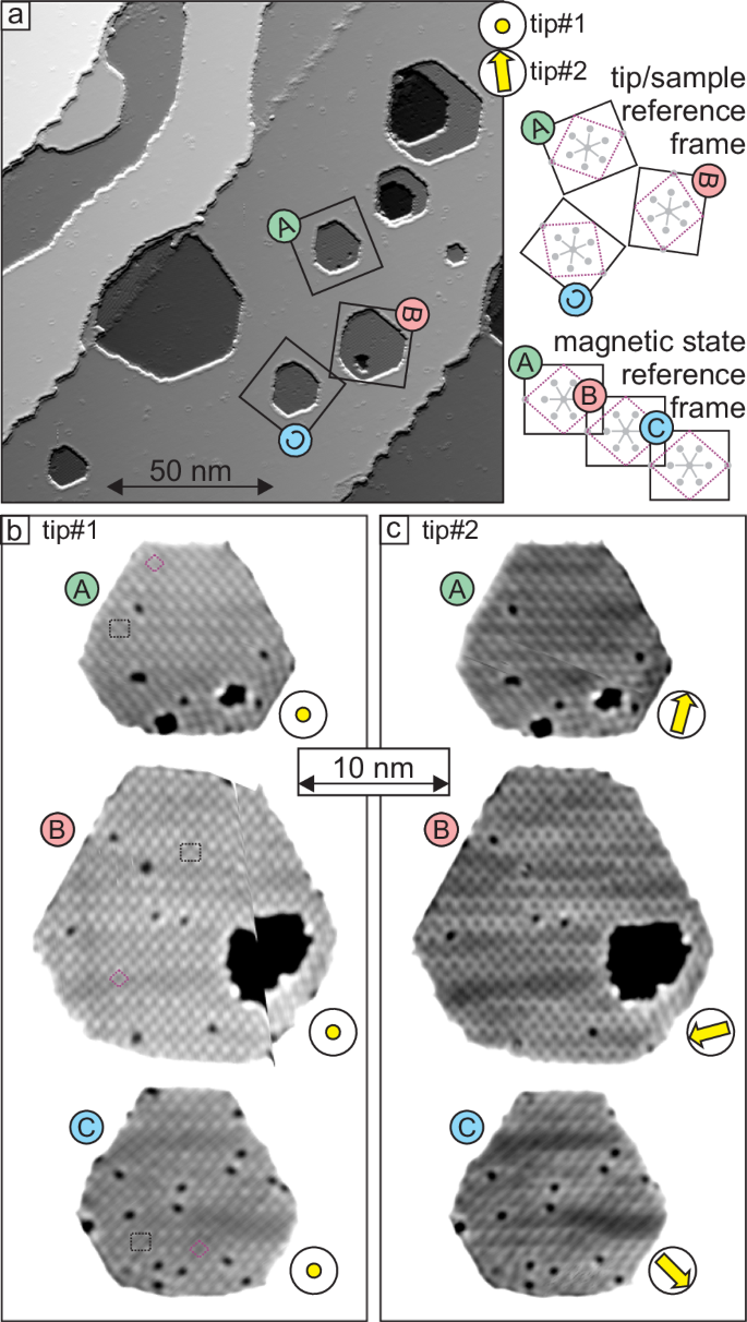
a Overview partially differentiated constant-current SP-STM measurement. b, c SP-STM measurements of the three Fe/Ir3 areas indicated by squares in (a), measured with two slightly different tips as indicated; the gray scale spans 40 pm; the yellow arrows refer to tentative tip magnetization directions and their relative orientation for the rotational magnetic domains. Sketches at the top right explain the connection between the SP-STM image in (a), and the zoomed and rotated areas in (b, c); the two derived possible magnetic unit cells are purple and black, and gray dots indicate the hexagonally arranged Fe atoms. Measurement parameters: a U = +100 mV, I = 1 nA; b U = +40 mV, I = 1 nA; c U = +5 mV, I = 4 nA; all: T = 4 K, Cr bulk tip; the glitch in island B of b stems from a briefly retracted tip and subsequent creep; the fast scan direction of the islands in b and c is along the horizontal axis of the overview image in (a).
Close inspection of the magnetic contrast shows that it is qualitatively similar in all three images of Fig. 1b, whereas the observed magnetic pattern changes for the rotational domains displayed in Fig. 1c. This is characteristic for a non-collinear magnetic state imaged with an out-of-plane magnetized tip in the first case (Fig. 1b), and a magnetic tip that also has an in-plane magnetization component in the latter case (Fig. 1c)17. Tentative tip magnetization directions are indicated in yellow to visualize the origin: the sample’s out-of-plane components always show the same pattern, regardless of the orientation of the magnetic unit cell; however, an in-plane magnetized tip will pick up different sample magnetization components depending on how the magnetic unit cell is rotated relative to the tip magnetization direction. For tip#2 a two-dimensionally periodic pattern is observed in islands A and B, whereas for island C a stripe pattern is found, which is reminiscent of the SP-STM measurements of the Fe monolayer on Ir(111), which exhibits a square nanoskyrmion lattice17.
First-principles calculations
To understand the origin of the magnetic ground state of Fe/Ir-3/Re(0001), we have performed first-principles calculations based on DFT (for computational details see “Methods”). We calculate the total energy of various collinear and non-collinear magnetic states with and without including spin-orbit coupling (SOC). We start with spin spiral states since these represent the general solution of the classical Heisenberg model on a periodic lattice and therefore allow to scan a large part of the magnetic phase space.
The energy dispersion E(q) of spin spirals in Fe/Ir-3/Re(0001) neglecting the effect of SOC (gray curve in Fig. 2) displays two minima along the high-symmetry directions (overline{Gamma })–(overline{{rm{M}}}) and (overline{Gamma })–(overline{{rm{K}}}) with an energy of about 5 meV/Fe atom below the ferromagnetic (FM) state ((overline{Gamma }) point) exhibiting a similar length of the spin spiral vector q. This indicates the stabilization of spin spirals by frustrated exchange interactions. Note, that the total energy scale of the dispersion is below 25 meV/Fe atom which is an extremely small value. This is due to a small FM nearest-neighbor (NN) exchange interaction which competes with antiferromagnetic beyond-NN exchange (values are given in Supplementary Table 1).
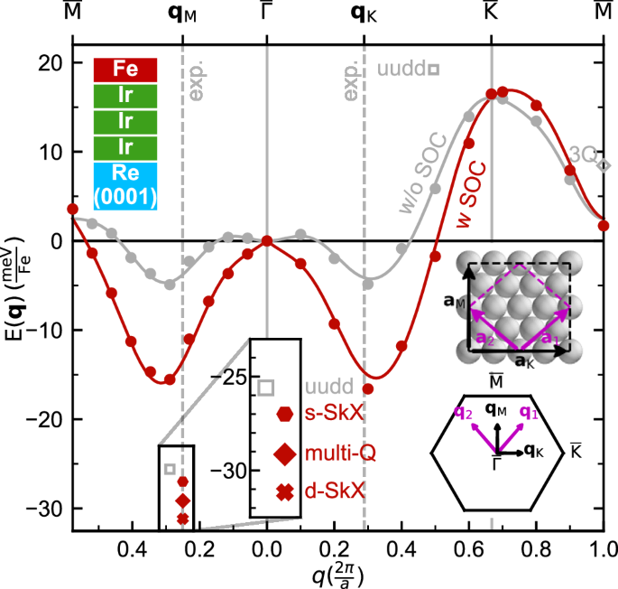
Energy dispersion of spin spirals obtained via DFT along the high-symmetry lines (overline{{rm{M}}})–(overline{Gamma })–(overline{{rm{K}}})–(overline{{rm{M}}}) with and without including SOC displayed by filled red and gray circles, respectively. The solid line represents a fit of the atomistic model to the DFT values. The total energies of the two uudd states and the 3Q state calculated via DFT are marked. The self-consistently calculated DFT total energies including SOC for the three spin lattices (Fig. 3) are also marked. All energies are given with respect to the FM state. In the inset the unit cells of the magnetic contrast is shown with the magnetic unit cell vectors a1 and a2 and aM and aK in purple and black, respectively obtained based on the experimental SP-STM images (cf. Fig. 1). The Brillouin zone is also sketched as an inset and the spin spiral vectors q1, q2, qK and qM are indicated. Dashed gray lines indicate the experimentally determined absolute values of qK and qM.
The influence of higher-order interactions (HOI) can be revealed by calculating the total energy of superposition states of spin spirals, so-called multi-Q states: the collinear up-up-down-down (uudd or double row-wise antiferromagnetic) states along both high-symmetry directions21,22,23,24 and the non-collinear 3Q state9,11,12,13. Within the Heisenberg model of pair-wise exchange these states are degenerate with the spin spiral (single-Q) states from which they are constructed. This degeneracy can be lifted by HOI. Therefore, a total DFT energy difference between single-Q and multi-Q states—obtained neglecting SOC in the calculation—is an indication of HOI. Note, that within DFT all magnetic interactions are implicitly contained within the exchange-correlation functional.
In Fig. 2 a clear deviation of the energies of the uudd and the 3Q states from the corresponding 1Q states is evident, which means that HOI exhibit a significant strength in this system. Out of the spin spiral states and the mentioned model-type multi-Q states the uudd state in (overline{Gamma M}) direction has the lowest energy by ΔE ≈ 20 meV/Fe atom lower than the minima of the single-Q state dispersion neglecting SOC (gray curve in Fig. 2). ΔE indicates the energy scale of the HOI.
The energy dispersion of spin spirals including the contribution of SOC, i.e., Dzyaloshinskii-Moriya interaction (DMI), is displayed in the red curve in Fig. 2 (for separate contributions see Supplementary Note 1 and Supplementary Fig. 1). Due to the DMI the minima in the spin spiral dispersion gain even more energy compared to the FM state, so that the energy difference is about 15 meV/Fe atom. As the DMI has no contribution to the collinear uudd state, the energy difference between the uudd state and the spin spiral of minimal energy is reduced by SOC.
To construct a superposition state with the experimentally observed magnetic unit cell (cf. Fig. 1), we convert the real space magnetic lattice vectors of the roughly square commensurate unit cell a1 and a2 into spin spiral vectors q1 and q2 in reciprocal space (see inset of Fig. 2). From q1 and q2 we can obtain spin spiral vectors qM and qK in the high symmetry directions (see inset in Fig. 2). These are given by ({{bf{q}}}_{{rm{M}}}=frac{1}{2}({{bf{q}}}_{1}+{{bf{q}}}_{2})=frac{pi }{2a}{hat{e}}_{y}) and ({{bf{q}}}_{{rm{K}}}=frac{1}{2}({{bf{q}}}_{1}-{{bf{q}}}_{2})=frac{pi }{sqrt{3}a}{hat{e}}_{x}), respectively, and they are related to the larger magnetic unit cell with lattice vectors aM and aK also observed in the experimental data. These q vectors are close to the energy minima of E(q) obtained from DFT calculations (Fig. 2). The size of the magnetic unit cell is defined by the interactions with the largest energy contribution, which are the exchange interaction and the DMI. Compared to the multi-Q state in Fe/Ir(111)17,25 the minima of the spin spiral calculations are at larger values of ∣q∣ for Fe/Ir-3/Re(0001) (Fig. 2). This leads to a reduction of the size of the unit cell.
The multi-Q state is constructed from these spin spirals using the analytical expression given in ref. 17 (see also “Methods” section) and its spin texture is displayed in Fig. 3a. Within DFT it is energetically significantly lower in total energy than the spin spiral minimum and a few meV/Fe atom lower than the uudd state along (overline{Gamma rm{M}}) (Fig. 2). The two-dimensional magnetic unit cell of the multi-Q state contains 16 atoms (Fig. 3a) and two spins point upwards with respect to the surface (red) and two spins point downwards (blue). All other spins are oriented in the film plane (green arrows). From the unit cell of the multi-Q state we can identify two substructures which show a spin configuration on an atomic scale reminiscent of an individual skyrmion or antiskyrmion (purple boxes in Fig. 3a).
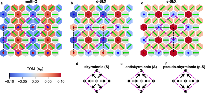
a multi-Q state, b double-skyrmionic lattice (d-SkX), and c single-skyrmionic lattice (s-SkX). The multi-Q state is constructed from a superposition of spin spirals with q vectors corresponding to the magnetic unit cell obtained in experiment (see text for details). The d-SkX lattice has been obtained from the multi-Q state by flipping two spins in the antiskyrmionic substructure to optimize the DMI energy. For the s-SkX lattice the antiskyrmionic substructures in the multi-Q state have been replaced by skyrmionic substructures to reduce the size of the magnetic unit cell. The dashed black (purple) box marks the magnetic unit cell of the multi-Q and d-SkX (s-SkX). The color of the hexagons display the topological orbital moment (TOM) for each atom calculated by DFT (see color bar at bottom). Red (blue) color denotes upwards (downwards) pointing TOM with respect to the surface normal. For the ease of discussion in the text, the centers of atomic-scale substructures of the spin lattices are denoted by letters: skyrmionic (S), antiskyrmionic (A), and pseudo-skyrmionic (p-S) which are also shown by the sketches in (d)–(f).
While these atomic-scale spin structures cannot be defined as skyrmions within a continuum description, they still share key properties of skyrmions such as vorticity and chirality of the spins surrounding the center. As a measure of their topological properties, we use the scalar spin chirality which is non-vanishing for these atomic-scale spin structures and is linked to topological orbital moments as discussed below and the topological Hall effect3,5,7,8. The two different upward pointing spins of the multi-Q state in Fig. 3a can be viewed as the center of an atomic-scale skyrmionic (S) or antiskyrmionic (A) building block of the lattice, respectively, compare purple boxes in Fig. 3a with Fig. 3d, e (In the same manner the downward pointing spins could be seen as the centers of equivalent substructures).
Topological orbital moments
In order to gain further insight into the properties of the multi-Q state we have calculated the topological orbital moment (TOM) per atom via DFT. In Fig. 3a, the TOM of every Fe atom is displayed by the color of the hexagon at the corresponding lattice site (for values see Supplementary Fig. 2). Note, that the skyrmionic spin structure possesses a positive TOM, while the antiskyrmionic spin structure exhibits a negative TOM, with the largest contribution at the positions of out-of-plane spins. Therefore, we observe rows of positive and negative TOM in the multi-Q state. The absolute value of the TOM, calculated by DFT, per skyrmionic or antiskyrmionic plaquette amounts to about 0.32 μB, while the sum of all TOMs in the black magnetic unit cell vanishes (For the contribution of a plaquette, we sum the contributions of all spins in the substructure, where the contributions from the corners are considered with an factor of (frac{1}{4})).
Starting from the multi-Q state, one can obtain other spin configurations consistent with the experimentally determined magnetic unit cell and we consider two other likely non-coplanar candidates. By inverting the two in-plane oriented spins in the antiskyrmionic substructure pointing along the x-direction (Fig. 3a), the magnetic state obtains the rotational sense favored by the DMI (Fig. 3b). This operation transforms the antiskyrmionic structure (Fig. 3e) into a new type of substructure which we refer to as pseudo-skyrmionic (labeled by p-S, see Fig. 3f). The resulting spin structure contains an atomic-scale skyrmionic and a pseudo-skyrmionic plaquette in the unit cell (Fig. 3b) and is denoted as double-skyrmionic lattice (d-SkX). The d-SkX state is even lower in total energy within DFT than the multi-Q state (Fig. 2).
In the d-SkX the TOM of the skyrmionic plaquette is 0.19 μB and thus similar to that in the multi-Q state. For the pseudo-skyrmionic substructure the TOM is smaller and inverted with respect to the corresponding antiskyrmionic plaquette in the multi-Q state (cf. Fig. 3a, b), leading to a checkerboard antiferromagnetic TOM order. The total TOM is still compensated.
Finally, we consider a spin texture which comprises only one type of skyrmionic substructure per unit cell (Fig. 3c), reminiscent of the nanoskyrmion lattice in the Fe monolayer on Ir(111)17. This single-skyrmionic lattice (s-SkX) is obtained from the multi-Q state by replacing the antiskyrmionic by a skyrmionic substructure. The s-SkX contains one skyrmionic plaquette and the resulting TOMs at the out-of-plane spins form a checkerboard pattern. In contrast to the previous two spin textures (multi-Q and d-SkX) the s-SkX exhibits a net TOM of about 0.17 μB per sykrmionic plaquette. If all spins of the displayed s-SkX are inverted an energetically degenerate state is obtained with a total TOM in the opposite direction, similar to the case of the triple-Q state13. However, in our DFT calculations the s-SkX is energetically unfavorable with respect to both the multi-Q state and the d-SkX (Fig. 2).
To understand the origin of these orbital moments emerging even without SOC, we compare the TOM calculated via DFT with an atomistic model. Within this atomistic model, the TOM at site i, ({{bf{L}}}_{i}^{{rm{TO}}}), can be related to the scalar spin chirality7:
where i, j, k denote neighboring lattice sites and the sum (jk) is over all pairs of neighboring lattice sites of site i. For the investigated lattices ({pmb{tau} }_{ijk}=hat{{bf{z}}}) is the unit vector along the direction perpendicular to the surface.
The scalar spin chirality is defined as χijk = si ⋅ (sj × sk) and only the spin structure is needed for its calculation. This makes Eq. (1) appealing to determine the TOM. Note, that the scalar spin chirality has also a profound effect on the transport properties of a magnetic material and can lead to a topological Hall conductivity in the absence of spin-orbit coupling5,8.
However, the topological orbital susceptibility ({kappa }_{ijk}^{{rm{TO}}}) depends on the electronic structure and can vary for each triangle (ijk). To obtain ({kappa }_{ijk}^{{rm{TO}}}) from our DFT calculations of the ({{bf{L}}}_{i}^{{rm{TO}}}), we assume it to be independent of the chosen triangle (ijk), i.e., ({kappa }_{i}^{{rm{TO}}}={kappa }_{ijk}^{{rm{TO}}}). Indeed, for all three investigated lattices, we find that ({kappa }_{i}^{{rm{TO}}}) is nearly independent of the site i of the Fe atom, which is consistent with a nearly constant Fe spin moment on all lattice sites (see Supplementary Fig. 2 and Supplementary Note 2).
The values obtained for the three different skyrmionic lattices show only a very small variation among them with ({kappa }_{i}^{{rm{TO}}}=0.019pm 0.002,{mu }_{B}) (see Supplementary Table 2 for all values). The calculated TOMs at the individual sites obtained within the atomistic model considering a constant orbital susceptibility agree very well with the ones calculated by DFT. This demonstrates that the spatial variation of the TOM originates mostly from the change of the spin structure, rather than from the change in the electronic structure, and that the atomistic model already gives a good approximation of the TOM. The nanoskyrmion lattice in Fe/Ir(111)17 shows a similar behavior, as the TOM is vanishing for the multi-Q state and non-vanishing if the skyrmionic structures are isolated by a scissor operation (for these data see Supplementary Note 3 and Supplementary Figs. 3 and 4).
Atomistic spin model
An atomistic spin model (see “Methods”) has been parameterized by the DFT data shown in Fig. 2, which includes pair-wise and higher-order exchange (HOI), DMI, magnetocrystalline anisotropy energy (MAE) and anisotropic symmetric exchange (ASE) (for details about the parameterization see Supplementary Note 1). The DFT total energies calculated with and without SOC for the multi-Q state, the d-SkX and s-SkX lattice are given in Table 1. The order among the three states is the same with and without SOC, but the values show that the s-SkX and the d-SkX states gain more energy due to SOC than the multi-Q state. The total energies of the spin model show the same trend as the DFT calculations.
The exchange, DMI, and four-site-four-spin interaction have the largest contribution to the total energy (for all values see Supplementary Table 1 and for the other interactions see Supplementary Note 4 and Supplementary Fig. 5) and we present their energy contributions per Fe atom in Fig. 4. Among the three spin structures, the multi-Q state exhibits the lowest exchange energy (Fig. 4a) which is due to the construction as a superposition of spin spirals close to the energy minima of the dispersion (cf. Fig. 2). Therefore, a flip of some spins increases the exchange energy as seen for the d-SkX (Fig. 4b). The s-SkX is the least favored lattice concerning the exchange interaction (Fig. 4c). Regarding the DMI the multi-Q state shows two rows with an opposite rotational sense with positive and negative contributions (Fig. 4d). By flipping two spins in the unfavorable row (bottom and top row in Fig. 4d) the rotational sense is switched and the DMI energy can be reduced. Therefore, compared to the multi-Q state, the d-SkX and the s-SkX optimize the DMI energy (Fig. 4e, f) with the same rotational sense in each row.
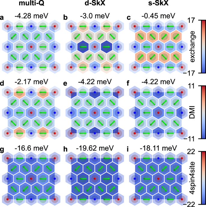
Energy contributions of a–c the exchange interaction, d–f the DMI, and g–i the four-site-four-spin interaction obtained in the atomistic spin model for the multi-Q state (left row), the d-SkX lattice (middle row), and the s-SkX lattice (right row). All energies are displayed with respect to the FM state. The interactions of all contributing shells of neighbors have been added. A scale bar is given for each interaction and above each plot the sum over all atoms in the unit cell is given. All energies are given in meV per atom.
All three spin lattices gain significant energy compared to the FM state due to the four-site-four-spin interaction (Fig. 4g–i). Regarding the four-site-four-spin interaction the flip of two spins in the bottom row reduces the energy of the d-SkX with respect to the multi-Q state. The reduction of the size of the unit cell from the d-SkX to the s-SkX is slightly unfavorable in terms of the four-site-four-spin interaction. The role played by the four-site-four-spin interaction is very similar to that in the nanoskyrmion lattice of Fe/Ir(111)17. Note, that the three-site-four-spin or the biquadratic interaction can also favor multi-Q states or nanoskyrmion lattices. However, in the system considered here these terms have only a minor strength (see values in Supplementary Table 1). The d-SkX is energetically most favorable among all considered spin lattices. It gains energy due to DMI and four-site-four-spin interaction with respect to the multi-Q state and due to exchange and four-site-four-spin interaction with respect to the s-SkX.
SP-STM simulations
For a direct comparison of the three spin lattices (Fig. 3) with the experimental data (Fig. 1), we simulated SP-STM images using the spin-polarized generalization of the Tersoff-Hamann model26,27,28. For an out-of-plane tip magnetization as shown in Fig. 5a–c all three lattices have the same roughly square contrast. These SP-STM simulations are in good agreement with the experimental magnetic contrast observed with tip#1 on all three islands in Fig. 1b. At the same time it becomes evident, that an out-of-plane tip is not suitable to distinguish between the three different proposed spin lattices. In contrast, different patterns are observed for the three different magnetic states when an in-plane magnetized tip is used, as evident from the SP-STM simulation in Fig. 5d–l. For each spin lattice a set of three different in-plane orientations of the tip magnetization has been used that are linked by 120° angles with respect to each other, such that they correspond to a fixed tip magnetization on three different rotational domains of the spin structure as observed in the SP-STM measurements for islands A, B, and C (Fig. 1c).
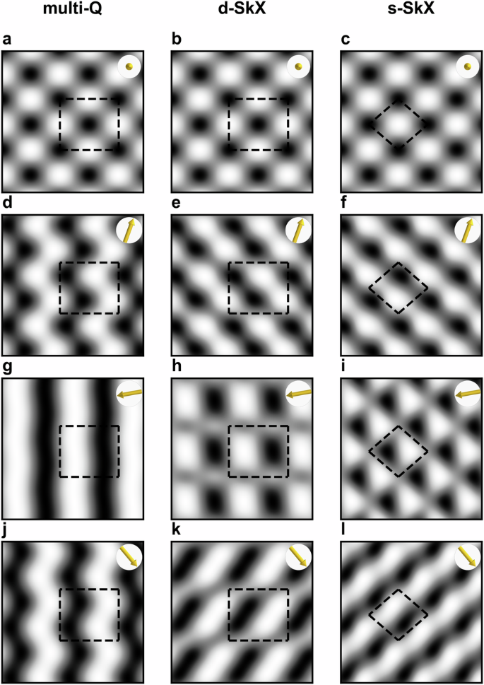
Simulated images are shown for a, d, g, j the multi-Q state, b, e, h, k the d-SkX, and c, f, i, l the s-SkX. For each spin lattice the simulated SP-STM image is displayed for an out-of-plane orientation of the tip magnetization (top row) and for three in-plane orientations of the tip with an angle of 120° between the different orientations (three lower rows). The tip magnetization direction is indicated in the top right corner of each panel by a yellow arrow and the dashed lines mark the magnetic unit cell as shown in Fig. 3.
One characteristic feature observed in the experimental SP-STM images are the stripes visible on island C. We find a similar pattern in our SP-STM simulations for the d-SkX and the s-SkX for an in-plane tip magnetization that is roughly perpendicular to the stripes, see Fig. 5k, l. However, such stripes are never observed for the multi-Q state, regardless of the tip magnetization direction. In contrast, for the multi-Q the simulations show wavy or straight stripes along the vertical direction for all in-plane tip magnetization directions, see Fig. 5d, g, j. Because this kind of pattern is not in agreement with the experimental results we rule out the presence of this multi-Q state in our system. The patterns for the d-SkX and the s-SkX resulting from the rotated tip magnetization directions in Fig. 5e-i can all be recognized in the experimental images of Fig. 1c, which makes a distinction between those two states challenging.
Discussion
We propose a spontaneous atomic-scale skyrmionic lattice as the magnetic ground state of an Fe monolayer on three atomic Ir layers on the Re(0001) surface. Our first-principles calculations reveal sizeable topological orbital magnetic moments with antiferromagnetic alignment for the different proposed spin textures which can be explained by the local scalar spin chirality due to the non-coplanar spin order in the skyrmionic lattices. The topological orbital susceptibility obtained via DFT is nearly constant for all Fe atoms in the lattice and is nearly independent of the considered spin lattice. This makes the atomistic model a very good approximation for the topological orbital moments. We find that Fe-based film systems have a significantly larger orbital susceptibility than Mn-based film systems13 (see Supplementary Table 2) which can lead to a larger topological orbital magnetization. This might make Fe-based thin-film systems interesting candidates for the emerging field of orbitronics and the observation of transport phenomena such as the topological Hall effect5,8.
Based on the comparison with the experiment, the multi-Q state can be ruled out as the magnetic ground state of Fe/Ir-3/Re(0001) in agreement with the DFT calculation. While in DFT the d-SkX is slightly lower in total energy compared to the s-SkX, in our experiments we cannot identify whether the d-SkX or the s-SkX is realized in our system due to the lateral variation of the apparent magnetic unit cell. Because Re becomes superconducting below 1.7 K such a zero magnetic field spin lattice is a promising candidate for future studies of emerging phenomena in atomic-scale non-coplanar magnet-superconductor hybrid systems29,30,31, including the role of topological orbital moments in proximity to a superconductor.
Methods
SP-STM experiments
The samples were prepared in a multi-chamber ultra-high vacuum system. The Re(0001) surface was cleaned by high-temperature flashes32 and Ir and Fe were evaporated from rods by electron beam heating18. Samples were then transferred in-vacuo into an STM that is operated at 4 K. The tip is made of Cr bulk material. The tip magnetization direction can be changed in-situ by gentle modifications of the tip apex. The spin-polarized contribution to the tunnel current scales with the projection of tip and sample magnetization directions, and the nano-scale magnetic order can be detected directly in constant-current imaging mode33.
DFT calculations
We have performed density functional theory (DFT) calculations to investigate the magnetic ground state and the magnetic interactions in Fe monolayers on three atomic layers of Ir on the Re(0001) surface. DFT calculations have been carried out using two different methods. We have used the all-electron code FLEUR based on the full-potential linearized augmented plane-wave (FLAPW) method (see https://www.flapw.de)34,35. In addition, we have applied the projector augmented wave (PAW) method as implemented in the VASP code36 (see https://www.vasp.at). Here we provide computational details of the calculations using both codes.
The FLEUR code has been used for spin spiral calculations34 neglecting and including spin-orbit coupling (SOC), and to obtain the total energies of the uudd states and the 3Q state. The SOC contribution to the energy of spin spirals was calculated using first order perturbation theory35. The magnetocrystalline anisotropy energy (MAE), defined as the total energy difference between the energy for a magnetization oriented along the in-plane and the out-of-plane direction, has been calculated self-consistently including SOC for the FM state37.
For all calculations using the FLEUR code the cut-off parameter for the basis functions has been set to ({k}_{max }=4.1,{text{a.u.}}^{-1}). The radius of the muffin-tin spheres was chosen as 2.45 a.u. for Re and 2.3 a.u. for Ir and Fe. The exchange-correlation (xc) functional for all calculations in FLEUR was chosen in local density approximation (LDA)38. For the spin spiral calculations with and without SOC a mesh of (44 × 44) k-points was used in the full 2D-BZ. The calculations for the 3Q state and the uudd states in their respective super-cells were performed on a (22 × 22) k-point mesh, which has the same density of k-points as that used in the spin spiral calculations. For the calculations of the MAE in the FM state a mesh of (223 × 223) k-points was used. For all calculations with the FLEUR code asymmetric films with one Fe layer, three Ir layers, and six layers of Re have been used. The Fe and Ir layers have been chosen in fcc stacking on the Re(0001) surface.
Structural relaxations of Fe/Ir-3/Re(0001) have been performed using the VASP code in the RW-AFM state. For the relaxations the GGA xc-functional PBE39 and a (15 × 15) grid of k-points was used. The multi-Q state, the d-SkX, and the s-SkX have been calculated in a supercell with 16 atoms per layer and the same number of substrate layers as in the spin spiral calculations. The cut-off of the wavefunctions was set to 268 eV and a grid of (15 × 15) k-points was used for these supercell calculations. The LDA xc-functional by Vosko, Wilk and Nusair38 has been applied. Topological orbital moments have been calculated using the VASP code. For fcc-Fe/Ir(111) they have been obtained based on the computational setup given in ref. 25.
Construction of the multi-Q state
The superposition of spin spirals defined by qM and qK under the constraint of a constant magnitude of the magnetization is given by the construction presented in ref. 17:
where Ri denotes the atomic site i and Si is the spin moment at this site. From Eq. (2) it is apparent that the spin exhibits a constant value of S at every lattice site. Note that qM and qK are obtained from the experimentally determined reciprocal lattice vectors q1 and q2 by ({{bf{q}}}_{{rm{M}}}=frac{1}{2}({{bf{q}}}_{1}+{{bf{q}}}_{2})) and ({{bf{q}}}_{{rm{K}}}=frac{1}{2}({{bf{q}}}_{1}-{{bf{q}}}_{2})), respectively.
Atomistic spin model
The atomistic spin model applied in our work contains exchange interaction, DMI, higher-order interaction (HOI), MAE and anisotropic symmetric exchange (ASE). The corresponding Hamiltonian is given by:
where si = Si/∣Si∣ denotes a normalized spin moment at a lattice site specified by i, (hat{{bf{z}}}) is the unit vector perpendicular to the surface and dij is the normalized connection vector between the lattice sites i and j. The interactions are sorted in shells according to the distance of the lattice sites. For all atoms of each shell the same interaction constants are assumed. For the exchange and the DMI the interaction parameters for the first ten shells have been calculated. For all other interactions only the interaction parameter of the first shell has been calculated.
SP-STM simulations
The simulations of SP-STM images are based on the spin-polarized generalization of the Tersoff-Hamann model26,27. We used a simplified SP-STM model in which the independent orbital approximation is applied28. In this model only the orientation of the magnetic moments with respect to the tip magnetization and the tip-sample distance are needed.


Responses