Array of micro-epidermal actuators for noninvasive pediatric flexible conductive hearing aids
Introduction
Conductive hearing loss (CHL) prevents transmission of sounds through the outer and middle ear to the cochlea1,2,3. Infection of middle ear, otitis media, is usually a temporary form of CHL that can be treated by antibiotics. Congenital CHL such as canal stenosis, atresia, and eustachian tube dysfunction are permanent and much more difficult to address4,5,6. The auditory canal may be reconstructed by corrective surgeries7,8. The permanent CHL can also be addressed by auditory osseointegrated implants (AOIs) that require a surgical procedure to implant an abutment into skull to transmit vibrations to cochlea through bone9,10. Corrective surgeries and AOIs are highly invasive for pediatric patients11,12,13. In addition, nonsurgical conductive hearing aids require a headband or a retainer to fix a mechanical transducer against skull that may be unstable on skull and cause skin reaction for infants14,15.
Flexible conductive hearing aids offer a noninvasive solution for addressing pediatric CHL16,17. These devices rely on a transducer to produce vibrations on the skin’s epidermal layer, which are transmitted through the skull bone to the cochlea, enabling sound perception. The thickness of flexible hearing aid cannot accommodate the conventional electromagnetic transducers. A key challenge in developing flexible aids is designing a thin, compact, and low-power transducer, which can generate a strong level of vibrations. Lead zirconium titanate (PZT-5H) has a high piezoelectric constant and can be used to create actuators that generate large displacements and high output force level18,19. By reducing the thickness of PZT transducers, they can be adapted for integration into flexible hearing aids. However, the vibration levels produced by piezoelectric (PZT) actuator are constrained by factors such as the available device voltage, actuator size, and structure20,21. Additionally, the attenuation of vibrations by soft tissues and flexible substrates further reduces their transmission strength to the bone, so that the transducers must generate enough vibrations to overcome the damping and vibrate basilar membrane in cochlea22,23.
Increasing the number of transducers to create an array is a viable solution to elevate the strength of vibrations from a flexible hearing aid. For optimal enhancement of resultant vibrations, the vibrational waves from the transducers must constructively interfere24,25. Factors such as phase alignment, frequency, and the properties of the propagation medium significantly influence the effectiveness of this interference. To enhance vibration levels on skull and cochlea, the phase of the voltages applied to each transducer, the array configuration, and the spacing between transducers must be optimized26,27,28. In addition, the existing hearing aids take advantage of directional microphones to reduce the background noise and localize the source of sounds. However, they lack a mechanism to control the directionality of the amplified vibrations on the skull. A unique feature of the flexible hearing aid with an array of transducers is to control the direction of vibrations from one ear to the opposite cochlea allowing to address unilateral and bilateral conductive hearing loss. The phase control allows vibrations to be amplified and directed toward far and near cochlea29,30.
Here, an array of PZT actuators are embedded in a polydimethylsiloxane (PDMS) substrate, termed as micro-epidermal actuators (MEAs), to increase the transmission of vibrations from the actuator to cochlea and control the direction of vibrations on skull. We designed, fabricated, and characterized two configurations for the array: horizontal and vertical as shown in Fig. 1. Our finite element analysis (FEA) and experimental results showed the level of vibrations from PZT arrays is improved compared to single MEA. In addition, our human subject study showed that flexible hearing aids with an array of PZT actuators improved the hearing threshold more effectively than an aid with a single transducer.

a Illustration of a horizontal array attached to a patient with aural atresia. Vibrational signals are generated by each actuator, constructively interfering with the bone to produce a stronger signal. The cochlea picks up the combined vibrations and transmits the auditory signal to the brain. b Schematic of a horizontal and stacked array in flexible substrates. c A single-phase hearing aid device with a stacked array. d Photos of each array attached to a human subject. e Finite element analysis (FEA) of a single actuator and arrays on a 100 mm radius, 3 mm thick bone at 7 kHz. Deformation is mapped from the displacement magnitude. Both the single PZT and stacked array generated symmetrical waves propagating outwards. The horizontal array generated vibrations that showed constructive and destructive interferences at various points of the bone disk.
Results
Principle of operation and design of micro-epidermal actuator (MEA) array
The mechanism of bone conduction with MEA arrays is illustrated in Fig. 1a. In this illustration, two transducers are placed on the skin of a patient with aural atresia. The transducers produce two distinct vibrations (red and blue in the figure) that bypass the initial layers of soft tissue and transmit to skull bone. The in-phase vibrations interfere constructively into a stronger signal (purple), which increases the strength of vibrations in the patient’s bone and cochlea. The vibration from the array is elevated relative to a single MEA, resulting in stronger auditory signals. The array of MEAs will allow amplifying the maximum strength of vibration produced by a conductive hearing aid and enable patients to perceive sounds. The hearing aid benefits from a phase control system to adjust the phase of signals on MEAs and improve the strength of resultant vibrations (Supplementary Fig. 1).
Figure 1b shows two configurations of MEA arrays: horizontal and stacked arrays. The arrays are composed of two MEAs made of circular lead zirconium titanate (PZT-5H) embedded in a soft elastomeric substrate. We used PDMS for the substrate for insulation and skin conformity. The horizontal and stacked arrays are designed to be 20 × 20 × 4 mm and 50 × 20 × 1 mm respectively. Figure 1c is a photograph of the stacked array attached to a hearing aid circuitry that converts sounds in the environment to electrical signals and amplifies the signals to be applied to MEA arrays. This circuitry features a −38 dB microelectromechanical system (MEMS) microphone and a 100 k gain across 2 stages of active filtering, on a 100 µm thin flexible polyimide substrate. Figure 1d and Supplementary Fig. 2 show the MEA arrays placed on the skin behind ear of a human subject. The power consumption of the MEA array is increased compared to a single MEA (Supplementary Fig. 3). Our results show that the circuit in the hearing aid consumes more power than MEAs; therefore, the addition of a second MEA increased the average power of the aid by ~15% (Supplementary Fig. 4). Figure 1e shows the FEA of a single and arrays of MEA on a circular bone disk at 7 kHz. The mode of vibrations for stacked arrays, in which the PZTs are vertically embedded in PDMS substrate, is identical to the mode from a single MEA. Both disks showed concentric modes radiating from the center of the disk and the MEA, where the maximum vibrations occur. The mode of vibrations for horizontal array, in which the MEAs are placed side by side, showed two peaks under the PZT disks.
Analysis of vibration from MEA array on geometrical shapes and human skull
An array with two MEAs generates two points of vibrations that propagate and interact with each other. The vibrations that are transmitted to the bone can be characterized by the wave equation and the superposition of waves24,25,31. The superposition theory dictates that when y1 and y2 are solutions for wave equation, their summation y is also a solution. The resultant vibrations are shown in the subsequent simulations (Supplementary Figs. 5–16). Superposition of vibrations on a disk is shown in Supplementary Fig. 5, where vibrations from each MEA are added to the disk. Figure 2a shows the vibrations from a single MEA and arrays of MEA on a spherical shell. The single MEA shows that the maximum vibration occurred under the PZT at 6 kHz. However, the constructive interferences for the stacked and horizontal array show two peaks on the side of the array on the spherical shell. Destructive interferences of the arrays at 6 kHz are shown in Supplementary Fig. 6, where the maximum vibrations reduced ~50% for the horizontal array and 25% for the stacked array compared to the maximum vibrations for the constructive interference of the arrays. We conducted analysis of constructive and destructive interference of vibrations from the arrays on a bone disk at 250 Hz (Supplementary Figs. 7–9). The results show that the maximum vibrations on the bone can be increased and reduced by adjusting the phase of applied voltages ∆φ on the actuators.

a 1 PZT and arrays on a 14-cm diameter, 3-mm thick bone shell at 6 kHz. We observe a change in modes with the inclusion of a second actuator for both horizontal and stacked arrays. b Comparison of 1 PZT and arrays on a human skull at 600 Hz. Arrays distribute the vibrations across a larger surface area. c Horizontal array on a skull at 250 Hz, comparing the mode changes at the constructive (top) and destructive (bottom) interferences. The vibrations that were present at the jaw were attenuated, and the back of the head was improved. d Vibrations on a human skull with and without a layer of skin, cerebrospinal fluid (CSF), and brain, at 7 kHz. Strength of vibrations is attenuated and the regions of vibration modes are reduced with soft tissue.
The interference of vibrations was analyzed on a model of a human skull with uneven surfaces and protrusions. Figure 2b shows the vibrations on the skull from a single transducer and arrays of MEAs at 600 Hz. The phase difference of electrical signals to MEAs was zero (∆φ = 0°) for the arrays. The vibrations are concentrated on a small area of temporal bone underneath the PZT actuator and at the mandible of the skull for a single MEA. The vibrations from a stacked array are more distributed across the right side of the skull at 600 Hz (Supplementary Fig. 10). For the horizontal array, vibrations are distributed across the skull and are more pronounced on the mandible at 600 Hz. We also analyzed the vibrations on the skull at 2 kHz and 8.2 kHz (Supplementary Figs. 11, 12). The results show that the mode shapes depend on the frequency, configuration of array, and geometry of the underlying object.
Figure 2c compares constructive (top) and destructive (bottom) modes for the horizontal array at 250 Hz. The vibrations were distributed on the right side of the skull where the array was placed as well as on the back of the skull at ∆φ = 345°. The maximum vibration was observed under the MEA array and on the mandible. When the phase difference of applied voltage was set to ∆φ = 165°, the vibration on mandible was destructive, and vibrations were only distributed on the right and back sides of the skull. The mode of vibration was extended to the topside of the skull and maximum vibrations were observed under the horizontal array at frequency of 1.25 kHz and phase difference ∆φ = 105° (Supplementary Fig. 13). At 4 kHz and ∆φ = 225°, the mode of vibrations shows multiple maximums on the temporal, parietal and mandible bones.
The mode of vibrations from the stacked array is less sensitive to phase change (Supplementary Fig. 14). This is attributed to the vertical alignment of two PZT actuators that are separated by only 3 mm. MEAs on the stacked array generate near in-phase waves that are more likely to interfere constructively at ∆φ = 0° and increase the strength of vibrations across the skull. The mode shape of the stacked array was similar to the mode of a single MEA on the flat bone (Fig.1e). The mode shape of the stacked array was different than single MEA on the skull at 600 Hz while the mode of vibrations was similar at 8.2 kHz (Supplementary Figs. 10, 12).
Skin and soft tissue of the human head attenuate the vibrations and affect their transmission on the skull bone32,33. Figure 2d shows the difference between the arrays on a skull with or without skin, cerebrospinal fluid, and brain tissue at 7 kHz. Attenuation of vibrations was observed for both arrays due to presence of the soft tissues. The mode shape was not changed for the stacked array with and without soft tissue. However, adding soft tissue to the skull model changed the mode of vibrations for the horizontal array. The maximum vibration on mandible was greatly reduced with the soft tissue in the model. We analyzed vibration transmission on geometrical shapes such as a disk and a spherical shell with soft tissues. The results show that the presence of soft tissues changed the mode and magnitude of the vibrations (Supplementary Figs. 15, 16).
Characterization of MEA arrays: vibrations’ strength, directionality, frequency, and phase response
We tested our stacked and horizontal arrays on geometrical shapes to have a deep insight into the interactions of vibrations from MEAs in the arrays. Figure 3a shows the experimental setup of horizontal array mounted at the center of an aluminum foundation with a thickness of 1 mm. The foundation was secured with foams to isolate vibrations. A laser Doppler vibrometer (LDV) was used to measure vibrations at the back of the foundation. Figure 3b shows the vibrations generated on the aluminum foundation from a stacked actuator. An average velocity of 127 dB (0 dB is 1 nm s−1) was produced by the top MEA and 130.5 dB from the bottom MEA. The vibrations from the top MEA are lower on the foundations since they transmitted through the PDMS layer and the bottom MEA. When both actuators are powered simultaneously, the average vibration is increased to 133.6 dB. This shows that both actuators in the array contributed to the total vibration, and the level of vibrations was increased by 6.6 dB compared to the top actuator. The interference of vibrations is not sensitive to the distance from the center of the stacked array as shown in Fig. 3c and Supplementary Fig. 17. The vibrations from each MEA on the stacked array are in phase on the foundation because of the alignment and small distance between MEAs in the array. Therefore, constructive interference was at 0°, and destructive interference at 180° at various locations on the foundation.

a Experimental setup of horizontal array on a 30.48 cm2 aluminum plate with a thickness of 1 mm. b Vibration level of a stacked array on a plate, each PZT individually powered, then powering both PZTs at 0° phase. The array’s vibration is higher than individual PZTs. c Changing the probing location with a 7 kHz input maintained a similar phase response for the stacked array. d Vibration level of a horizontal array of the first, second, and both PZTs powered at 0° phase. The total vibration from the array is higher than a single actuator. e Phase response of 2 different frequencies measured underneath the horizontal array’s center. f By probing 3 cm away, the phase responses shifted for the horizontal array. The destructive interference for the 3 kHz response is at 0°. g At the same 3 cm distance, the vibration level of 0° phase response is measured against the constructively interfering phases (optimized). The vibration’s strength improved by13 dB at 5 kHz and an average improvement was 3.5 dB. The minimum vibrations improved from 121 dB (2.46 mm s−1) to 130 dB (5.63 mm s−1). h Frequency response of different-sized PZTs for the horizontal array. Each sized PZT has its own vibrational response, and the summation merged all the peaks detected at 5, 7, and 9 kHz. i Increasing the phase of the horizontal array shifted the vibrational peak by a distance of d. The probe at d = 0 is 9 cm down from the center of the array.
Figure 3d shows the vibration level of a horizontal array. Each individual actuator produced a similar magnitude of vibration (131.4 and 131.1 dB) at the center of the array. Powering both MEAs in the array increased the average vibration to 136.5 dB. Figure 3e shows the phase response of a horizontal array. The velocity of vibrations showed a constructive interference at 300°, and destructive interference at 120° for 3 and 6 kHz. The interference of vibrations from the MEAs in the horizontal array is sensitive to the distance. Figure 3f shows that the constructive interference of vibrations shifted from 300° at the center of the array to 180° and 90° at 3 cm distance from the center of the array for 3 and 6 kHz. This requires phase control for the horizontal array to increase the level of vibration at various locations and frequencies. Figure 3g shows the velocity of vibrations for a horizontal array at 0° phase vs. adjusted phase across the 10 kHz spectrum. Phase control increased the velocity by a maximum of 12.8 dB at frequencies under 6 kHz. The minimum vibration was increased from 120.8 dB to 130.1 dB through phase adjustment. The array of dissimilar MEAs allows engineering the bandwidth of resultant vibrations34. Figure 3h shows the frequency response of individual MEA with the diameter of 20 and 27 mm as well as the frequency response of the array when both MEAs are powered. The 20-mm MEA had two resonance peaks at 7 kHz and 9 kHz, while the 27-mm MEA had one resonance peak at 5 kHz. The response for the array contained all three resonance peaks at 5, 7, and 9 kHz. At a 3-cm distance from the center of the dissimilar array, the phase control was used to increase the level of vibrations at various frequencies (Supplementary Fig. 18). Moreover, the phase control of the array allows changing the directionality of the vibrations28,30. Figure 3i shows phase adjustment shifted the point of maximum vibration. By increasing the phase of the horizontal array, the resonant peak moved across a line on the aluminum foundation. In addition, we tested the arrays on a spherical shell with a 15-cm radius to study the vibration transmission (Supplementary Fig. 19). The data showed the phase response of horizontal array was also sensitive to the location on the sphere.
Improvement of human subjects’ hearing with MEA arrays
A human-subject study was conducted to evaluate the performance of arrays on the hearing threshold (HT) of the participants. In addition, we measured the minimum voltage required to be applied on the MEAs in the array to conduct vibrations from the epidermis to cochlea. The protocol for human subject study was reviewed and approved by the Institutional Review Board of Rowan University before the study started. Ten individuals between the ages of 19–39 participated in the study (Supplementary Table 1). Each subject was given earplugs and earmuffs to have simulated conductive hearing loss (SCHL). The experiments were conducted in a quiet room that was acoustically insulated (Supplementary Figs. 20, 21). The arrays were connected to the hearing aid circuit shown in Fig. 1c. The devices were placed behind the right ear of the subjects and affixed with a medical tape.
Figure 4a compares the HT of individuals with a single MEA vs. a stacked array with two MEAs at 0° phase. The stacked array improved HT average from the participants by 12.1 dB at 250 Hz and 13.8 dB at 500 Hz compared to a single MEA. The average HT was increased by 6.71 dB across 0.25–8 kHz (Supplementary Table 2). HT improvements from the array across all frequencies were statistically significant with p value lower than 0.05. Compared to the unaided HT, the array improved a subject’s HT by 30.5 dB at 1 kHz, and 20.41 dB across 0.25–8 kHz (Supplementary Fig. 22). All the participants reported that the quality of sounds from the array was much clearer than a single actuator. Eighty percent of the participants with SCHL noted that the hearing aid with MEA array assisted them in hearing low-level sounds in the room (e.g., typing on keyboard, airflow from AC systems). Figure 4b shows the minimum voltage required to drive the MEAs, at 0° phase, to enable the participants with SCHL to hear sounds from the MEAs. Horizontal and stacked arrays decreased the threshold voltage by up to 84% compared to the minimum voltage required for a single MEA to enable hearing across 0.25–8 kHz. The grand mean decrease across the same frequency band was 71% (Supplementary Table 3). Statistical analysis using one-sided T-test showed the p value is less than 0.05 and thus, data are statistically significant.
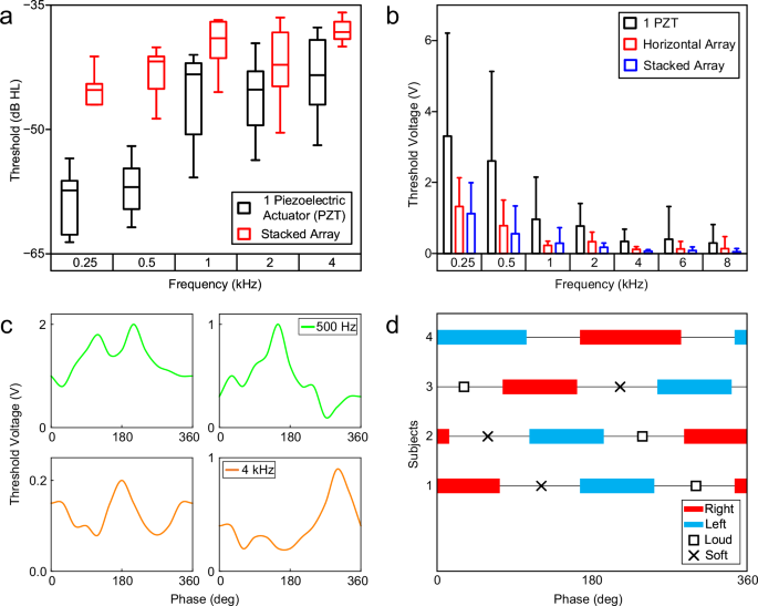
a Hearing levels of subjects with simulated conductive hearing loss, using a hearing aid with one MEA or a stacked array. At lower frequencies, the hearing levels improved by 12 dB and 15 dB for 250 Hz and 500 Hz. b Minimum voltage required for the MEA/array to produce an audible vibration for the subject. Both arrays were powered at 0° phase and performed better compared to a single PZT actuator. The error bars of a and b represent the standard deviation from measuring 10 subjects. c Phase response of 4 subjects with a horizontal array at 500 Hz (top) and 4 kHz (bottom). Constructive (lowest threshold voltage) and destructive (highest threshold voltage) interferences were generally 180° apart. d Directionality of horizontal arrays for 4 subjects at 500 Hz. The range for each direction is 90°–120°, followed by the perceived maxima/minima.
Furthermore, we evaluated the effect of the phase of horizontal array on the threshold voltage. Figure 4c shows the phase response of the threshold voltage to enable participants to hear sounds at 0.5 and 4 kHz. The data showed that the phase can be adjusted to reduce the threshold voltage. Sixty percent of the participants reported that they hear sounds from the right ear, where the array was attached to, at various phases and frequencies (Supplementary Tables 4, 5). However, 40% of the participants reported that phase adjustment can change the directionality of the perceived sounds. They noted that they heard the sounds, that originated from the array on the right side, in the left ear (Fig. 4d). Three participants reported that sounds were coming from the back of their heads at phases between highest and lowest sounds. This may be attributed to bone shape, bone density, skin thickness, and tissue distribution that affect vibration transmission and interference.
Discussion
The flexible hearing aid is a noninvasive and accessible option to address CHL in the early stage of life and enables pediatric patients to adapt to the naturally occurring sounds in the environment. The device could improve communication skills, reduce delays in language and speech development, and improve educational outcomes for pediatric patients. The flexible Band Aid®-like hearing aid is not noticeable and it could motivate younger children to wear the hearing aid without any stigma. The flexible hearing aid is low cost and will be accessible to patients from a diverse socioeconomic status.
MEAs in flexible conductive hearing aids generate vibrations on the epidermal layer of the skin. To improve the level of vibrations and overcome the damping from the actuator to the cochlea, we designed, fabricated, and characterized an array of MEAs. Our FEA and experimental results showed that the arrays generated and transmitted more vibration compared to a single transducer. Vibrations from two 15-mm diameter transducers were constructively interfered with and generated ~140-dB vibrations on the flat and spherical foundations. In addition, we used a dissimilar array with two MEAs with different diameters to flatten the frequency response. Our human subject study showed that stacking two transducers improved HT by 13.8 dB at 500 Hz compared to a single transducer. Our experiments showed that horizontal array requires phase control to increase the level of vibrations and guide vibrations to right or left cochlea, while the stacked array showed a strong level of vibrations at phase zero. An array of two MEAs in either configuration decreased hearing voltage thresholds by 71%.
In conclusion, arraying MEAs increased the strength of vibrations, flattened the frequency response of the hearing aid, and improved the HT of the participants. In the future direction, we will improve the electronic circuits to reduce power consumption and improve the quality of sounds through a frequency equalizer. In addition, we will add a knob on the device to enable users to change the gain of the aid and achieve their desired level of sounds. We will also package the device with electronics, batteries, and MEAs into a soft material to be comfortable and easy to use. Moreover, we will conduct a multi-site clinical trial on patients with various levels of conductive hearing loss to evaluate the efficacy and safety of the device.
Methods
Finite element analysis
A model of a human skull was created in COMSOL Multiphysics 6.2.0.290 software to conduct the finite element analysis (FEA) of vibrations. Lead zirconium titanate (PZT-5H) was used for piezoelectric layer in the micro-epidermal actuator (MEA). The model of the MEA was constructed with a 5-mm radius, 100-µm thick PZT-5H disk on a 7.5-mm radius, 100-µm thick copper disk. To examine the vibration transmission on geometrical shapes, disks, and spherical shells were created in the software with a thickness of 3 mm. The spheres had a radius of 70-mm, and the disks had radius of 100- and 200-mm. Thickness of the skin placed on the model of the disks and spheres was 1 mm. Each model was simulated from 0.2 to 10 kHz at 100 Hz intervals and 0–360° phase at 15° intervals. The thickness of skin on the human skull model varied from 1 to 5 mm. A 17-mm thick cerebrospinal fluid layer was modeled between skull and brain tissue (Supplementary Fig. 23).
Materials
MEA fabrication
The fabrication for both horizontal and stacked arrays is shown in Supplementary Fig. 24. We started by depositing a 100-µm thick SylgardTM 184 polydimethylsiloxane (PDMS) with a 1:10 ratio (1 part: curing agent and 10 parts elastomer base) in a container. For the horizontal array, 15-mm-diameter PZT-5H transducers were placed on the initial PDMS layer, and another 900-µm thick PDMS layer was poured over the PZTs. This forms a total device thickness of 1 mm. For the stacked array, a 3-mm thick PDMS was poured over the PZT. Another PZT was placed on top of the second PDMS layer, aligned with the bottom PZT. A 900-µm thick layer of PDMS was poured onto the structure, forming a total device thickness of 4 mm. Both arrays, once cured, had wires connected to silver pads on the PZT layer and to the brass disk.
Fabrication of hearing aid circuit
The circuit used for amplifying sounds and powering the transducers is shown in Fig. 1c and Supplementary Fig. 25. The hearing aid circuit was screen-printed on a 100-µm polyimide substrate. The components of the circuit were surface mounted on the substrate. A microelectromechanical microphone (model number INMP510) picked up sounds from the environment and converted the sounds to electrical signals. The signals passed through two stages of active filtering separated by buffers, leading to the output voltage connected to the MEA. The model of operational amplifiers is TL071H.
Materials, components, and designs
Polydimethylsiloxane (PDMS) was chosen as the encasing material and the substrate for the arrayed device, primarily because PDMS is soft, flexible, and biocompatible. It has been established as an interface material for medical devices on human skin35. Lead zirconium titanate (PZT-5H) was used due to their high piezoelectric coefficient, which translates to a high vibrational force produced with a low voltage input. Electronic components are surface-mounted technology (SMT) to have more components on the flexible hearing aid and reduce the cost of manufacturing. Stacking the transducers on top of each other, vertical array, allows interfering vibrations constructively and increases the strength of vibrations. Having the transducers side-by-side, horizonal array, ensures the direction of vibrations can be changed by controlling the phase of applied voltages on the actuators.
Device characterization
The single MEA and arrays of MEAs were attached with an industrial tape (Gorilla Tough & Clear Mounting Tape) on a 1-mm thick, 30.48 cm2 aluminum plate (flat foundation) and on a 15-cm radius aluminum spherical shell. The aluminum foundations were secured with foam and holders to isolate vibrations from the table. Measurements of the velocity were conducted with a laser Doppler vibrometer (OMS Laser point LP01). A 2-channel function generator was used to generate sinusoidal signals with a peak-peak voltage of 10 V and an offset of 5 V.
Human subject study
The protocol for human subject study was reviewed and approved by the Institutional Review Board (IRB) of Rowan University (PRO-2023-334) before we started the study. The participation in the study was completely voluntary, and a consent form was obtained from each participant. In addition, verbal consent was obtained from the participants before starting data collection. We informed participants that they could leave the study at any time. No participants left the study during the experiments, and no complaints were received from the subjects during and after the experiment. All participants were very cooperative across the entire testing process.
Participants sat in a quiet room, wearing noise-cancellation earplugs and earmuffs to have simulated conductive hearing loss (SCHL). For hearing threshold measurements, the hearing aid circuit with MEAs was attached to the skin behind the right ear of the participant. Tones were generated using a speaker, while an SPL meter was ongoingly measuring the sound pressure level (Supplementary Fig. 20).
Voltage threshold measurements were conducted by replacing the circuit with a two-channel function generator, in which the minimum voltage level to drive the device for the participants to hear was recorded for each frequency. The same method was used for the phase tests, with the frequencies fixed at 0.5 and 4 kHz. The directionality test was conducted with the peak-peak voltage at 5 V and an offset of 2.5 V.
Statistical analysis
We conducted one-sided T-tests of equal and unequal variances of mean for statistical analysis comparing the arrayed device with the control with a single actuator for the hearing threshold of subjects with simulated conductive hearing loss. The analysis showed that p value is less than 5% which is statistically significant (p value < 0.05) across all frequencies as shown in Fig. 4a and Supplementary Table 2. Additionally, the voltage threshold comparison between both arrayed devices and the control device is statistically significant for the frequencies ranging from 0.25 to 4 kHz (Fig. 4b and Supplementary Table 3). Overall, the device showed promising success in improving the hearing level of human subjects. The sample size was n = 10 for all tests. Statistical analysis was performed using the R programming language.
Device biocompatibility and eco-friendliness
Flexible hearing aids are noninvasive and placed on skin behind the ear, so biocompatibility is predominantly determined by evaluation of surface interactions with skin. Polydimethylsiloxane (PDMS) at the bottom of the hearing aid is in contact with skin. PDMS is hypoallergenic, permeable, stable, and biocompatible35. PDMS is safe on soft tissues and has been used in many medical devices such as contact lenses and ultrasound sensors. Other components of the hearing aids including batteries and electronic components are safe and do not have any risks to the users. To further reduce any effects from these components, they are not in contact with skin and are covered by PDMS or the medical tape (e.g., Band-Aid) on top of the device. The PZT-5H in the micro-epidermal actuator is not biocompatible and must be secured and isolated from skin and body. The thickness of the PZT is only 100 µm and was sandwiched between a brass plate and a thin layer of silver. In addition, the PZT actuator was embedded into PDMS that is biocompatible. PZT-5H is not in direct contact with skin and is isolated with brass, silver, and PDMS; therefore, the risk is extremely low. According to datasheets provided by vendors, the electronic components of the hearing aids meet the requirements of Restriction of Hazardous Substances (RoHS). The electronic components in the device are RoHS compatible and do not have dangerous materials.
PDMS was noted to have no harmful effects to the environment, hence, they are not an environmental hazard36. Other components also do not have any major risk for the environment. The batteries, the electronic chips, and micro-epidermal actuator with PZT materials on the device are required to be disposed according to local and national instructions for disposal to minimize the risk for the environment.
Reporting summary
Further information on research design is available in the Nature Portfolio Reporting Summary linked to this article.
Responses