Autonomous self-healing in a stretchable polybutadiene-based urethane and eutectic gallium indium conductive composite

Introduction
The exploration of wearable and flexible electronic devices continues to advance significantly as the global demand for sophisticated healthcare monitoring systems, intelligent mobile technologies, and related applications intensifies1,2,3. These developments necessitate materials and components that not only retain their functionality over prolonged periods but are also engineered to be stretchable—possessing sufficient rigidity to endure typical environmental challenges without degradation4. Among the myriad configurations of pliable electronics, thin-film technologies have emerged as particularly prevalent, owing to their minimal thickness and a Young’s Modulus that mirrors that of human skin, facilitating compatibility and comfort5,6. The availability of numerous polymers capable of yielding skin-friendly thin films has largely addressed concerns related to user interface; the current challenge, however, lies in identifying a dependable conductive medium that can efficiently facilitate electrical conduction across various structural formations.
Historically, flexible conductive materials such as the percolated networks of silver nanowires (AgNWs) and electrodes based on two-dimensional materials have been extensively documented. These materials exhibit commendable performance under minimal strain conditions. However, they are prone to irreversible damage and subsequent performance deterioration when subjected to extensive strains, exceeding tens of percent7,8. In this context, the emergence of so-called liquid metals, which remain liquid at room temperature, represents a transformative development. These substances are not only impervious to damage from structural alterations but also exhibit the high electrical conductivity characteristic of traditional metals, positioning them as promising candidates for flexible electrode applications9. Eutectic gallium-indium (EGaIn), a specific category of liquid metal, has garnered particular interest. Beyond the aforementioned benefits, EGaIn distinguishes itself by its biocompatibility. Unlike mercury, a substance known for its potential to adversely affect the respiratory and nervous systems, EGaIn is deemed safe for direct physical interaction10,11. This safety profile, combined with its physical and electrical properties, has facilitated the widespread integration of EGaIn into various research domains, including inkjet printing technologies, microfluidics, and microelectronic integrations, among others12,13,14. For instance, Lu et al. successfully created a Fe@PDA-Ag shell surrounding the liquid metal to improve the electrical and thermal performance of the liquid metal magnetic suspenstions15. This broad applicability underscores the potential of EGaIn as a pivotal material in the ongoing evolution of wearable and flexible electronics, promising to address current limitations while opening new avenues for innovation.
The inherent fluidity of EGaIn at room temperature, while offering unique advantages in terms of electrical conductivity and flexibility, also poses significant challenges in terms of device stability and durability. This fluidity leads to a precarious adherence of EGaIn to substrates, particularly when subjected to physical forces or alterations in orientation, which can result in the separation of EGaIn from the substrate. The theoretical foundation for this behavior lies in the principles of fluid dynamics and surface tension. The adhesive forces between the liquid metal and the substrate must overcome the cohesive forces within the liquid metal itself to maintain a stable interface. When external stresses disrupt this balance, detachment occurs, compromising the electrical pathways critical for device functionality. To address these challenges, recent research has explored the amalgamation of EGaIn with various polymers, aiming to leverage the viscoelastic properties of polymers to enhance adhesion and stability without significantly detracting from the electrical performance of EGaIn9,12,13,15,16.
The approach to amalgamate EGaIn with polymers is underpinned by advanced concepts in polymer science which take into account the influence of polymer morphology on material properties. Through careful modification of molecular weight, cross-linking density, and copolymer composition, polymers can be synthesized to span a spectrum of mechanical properties, ranging from high elasticity to increased rigidity. For example, Zu et al. mixed silver micro flakes with bi-phasic AgInGa-SIS conductor and investigated the flakes’ effect on the composite’s conductivity, the optimized sample had a conductivity of 6.38 × 10⁵ S/m with high strain limit (more than 1000%). However, their sample did not have the self-healing ability17. On the other hand, Rahmani amalgamated liquid metal nanoparticles were dispersed with CNC-containing hydrogel to stabilize the liquid metal suspension, thus the gel has extreme toughness (∼1.8 MJ/m3), good conductivity and piezoionic properties but the hydrogel could only be self-healed after 8 h18. This meticulous engineering enables the creation of composites which not only robustly bond EGaIn to substrates but also maintain the pliability required to meet the dynamic demands of wearable electronics. Despite the promising aspects of this approach, it ushers in intricate interactions between the composite’s mechanical resilience and its ability to heal autonomously. From a theoretical standpoint, the field of composite materials illuminates the inherent tension in achieving equilibrium between these two attributes. Augmenting the composite with polymer enhances mechanical stability and can mitigate leakage of EGaIn; however, it might concurrently restrict the natural, fluidic behavior of EGaIn that is essential for self-repair. This restriction stems from fundamental discrepancies between the metallic properties of EGaIn—characterized by quick and reversible restoration via fluid movement and droplet coalescence—and those of polymeric substances, which are typically defined by permanent deformation or rupture under duress.
The self-healing characteristic of EGaIn is essentially a reflection of its capacity to reduce surface energy through the merger of discrete droplets, propelled by the metal’s substantial surface tension. In stark contrast, polymers, particularly when cross-linked, are not predisposed to such reversible actions, owing to their solidified state and the enduring nature of their cross-linked junctions. Consequently, while the polymer matrix acts as an anchor for EGaIn, it also has the potential to limit the motion of EGaIn particles, thereby hindering their propensity to coalesce and self-mend in the event of damage. Several composites have been introduced to advance the field of liquid metal-based soft electronics, each with its own set of capabilities and limitations19,20. For instance, cross-linked block copolymers showcased remarkable elasticity and inherent self-healing abilities, yet they lacked the ability for intricate patterning and required significant pressure to initiate conductivity21,22. In contrast, certain polydimethylsiloxane (PDMS)-EGaIn composites offered precision in conductive patterning but were characterized by a lower threshold for strain (up to 100%) and lacked self-healing properties23,24. Alternative matrices, such as fibrous structures, presented high tensile strain capacities, yet similarly fell short in self-repairing functionality25,26,27. In the particular case of PDMS-EGaIn composite electrodes, the theoretical considerations emphasize the compromises involved. PDMS is prized for its high flexibility and compatibility with biological tissues, enhancing the composite’s pliability and stretchability. Nevertheless, should damage befall the composite, PDMS’s elasticity does not inherently support the reintegration of EGaIn, thus disrupting the liquid metal’s innate self-healing process. This delineates a critical area for further research and development to optimize the synergistic properties of polymer-liquid metal composites for electronic applications.
Herein, the composite’s core is a polybutadiene-based urethane (PBU), chosen for its thermo-reversible Diels–Alder reaction attributes. The Diels–Alder reaction is a selective and efficient cycloaddition that yields a cyclohexene system, and crucially for this application, it can reverse at higher temperatures, allowing the material to “self-heal” by reverting Diels–Alder adducts to the original diene and dienophile at around 120 °C. The controlled reversibility of covalent bonds formed during the Diels–Alder reaction empowers the PBU matrix to repair itself after damage. To minimize side reactions at elevated temperatures and preserve the composite’s integrity, furan-maleimide is incorporated due to its strong affinity for forming reversible links. The liquid metal-polymer blend was optimized using percolation theory principles, carefully calibrating the ratio and mixing speed to ensure the conductive filler forms a network without spilling out, considering EGaIn’s tendency to separate due to high surface tension. Mechanical durability is showcased by minimal resistance variation under extensive deformation, attested by extensive cycling tests. The composite’s thermal properties enable self-healing without material degradation. Post-healing, the composite regains its original strain rate, indicating excellent potential for dynamic use. This composite material has been adeptly engineered to function as an efficacious heating element, and it has demonstrated a propensity for autonomous self-healing concurrent with the thermal emission process. For precise patterning critical for electronic functionality, a stencil mask technique was applied, allowing for the creation of intricate, sharp-edged designs at the micro-scale. The composite has demonstrated high accuracy and sensitivity as a motion detector, responding to minute movements, which proves its promise for integration into sophisticated electronic systems and self-healable and stretchable wearable devices.
Results
Percolation for the composite
Figure 1a provides a concise overview of the characteristics and potential applications of the flexible composite. This composite comprises a PBU matrix and an EGaIn conductive filler. The resulting PBU-EGaIn composite exhibits flexibility, self-healing capability, and patterning potential, rendering it suitable for applications such as motion detection, heat transfer, and stretchable circuits. First of all, in pursuit of establishing the optimal EGaIn proportion to enhance the electrical conductivity within the composite framework, a meticulous series of syntheses was executed, incorporating varying concentrations of EGaIn. Quantitative electrical resistance measurements were carried out for composites with EGaIn loadings ranging from a minimal 5% up to a substantial 50%. It was observed that the resistance exhibited a significant diminution upon incorporating 50% of the alloy, declining precipitously from an initial magnitude of ~105 Ω to a markedly lower 83 Ω. This substantial reduction signals the approach toward the percolation threshold, a critical juncture characterized by the formation of a continuous conductive cluster that markedly enhances electron mobility within the composite (as illustrated in Fig. 1b). Further morphological elucidation was conducted using an optical microscope (OM) (Supplementary Fig. 1). It was discerned that at EGaIn incorporations beneath 33%, the metal particulates—exhibiting an assortment of shapes—were homogeneously distributed throughout the PBU substrate. Despite this distribution, the particulates remained distinct and electrically discrete. At a concentration of 50% EGaIn, the emergence of nascent EGaIn collectives was noted, yet these assemblies did not coalesce into a pervasive conductive network. Elevating the EGaIn content to 55% precipitated a substantial decline in electrical resistance, as per the analyses. This observation was corroborated by surface examinations that verified the conductivity enhancement was a direct consequence of the interconnected network formed amongst EGaIn droplets. These droplets, predominantly within a 10 μm diameter range, exhibited non-spherical geometries, a manifestation of the diminished surface energy resulting from the enveloping urethane matrix28,29. Upon examining samples with 67% metal loading, a denser metallic network was apparent, yet this did not correspond to a discernible resistance decrement. Consequently, in light of the comprehensive electrical and morphological insights, the composite formulation endowed with 55% EGaIn was elected as the superior candidate for the development of the PBU-EGaIn composite, optimizing electrical conductivity whilst upholding the structural cohesion of the composite.

a Schematic illustration of the PBU-EGaIn’s properties and applications; b Graph showcasing the percolation threshold as a function of varied EGaIn volumetric ratios; c A plot delineating the correlation between resistance stability and the velocity of planetary mixing (EGaIn wt.% = 55%; Strain level = 135%); d XRD patterns contrasting the molecular structure of unadulterated PBU with the EGaIn-infused PBU composite; e A distribution analysis of EGaIn particulate diameters within the composite, correlated with a mixing speed of 2000 rpm (EGaIn wt.% = 55%).
In the realm of composite materials science, the size of particles within a matrix is a paramount consideration, particularly when dealing with a substance such as liquid metal which exhibits a high surface energy. This intrinsic characteristic of EGaIn is pivotal as it significantly influences the propensity of the metal filler to breach the confines of its host polymer matrix. In an endeavor to rigorously scrutinize this phenomenon, the mixing speeds were modulated across a spectrum of 800 to 2000 rpm, all the while maintaining a constant EGaIn mass fraction at 55% (Fig. 1c). The cyclic strain test was meticulously deployed to ascertain the impact of EGaIn droplet dimensions on the composite’s performance, denoted as PBU-EGaIn. Scientifically, it was ascertained that there exists an inverse correlation between the planetary mixing velocity and the composite’s mechanical stability; however, the variation in electrical resistance over an extended period of 10,000 s did not demonstrate notable fluctuation, plateauing at a resistance value of ~2.65 Ω. Disparities in the samples’ resistivity were less pronounced, yet the mechanical response of the composites under tensile stress was divergent. During the dynamic cyclic strain tests, a slight upward drift in resistance was observed over time. This phenomenon can be attributed to the dynamic interplay between the viscoelastic properties of the PBU matrix and the fluidity of the embedded EGaIn microparticles. When the composite is subjected to cyclic strain, the EGaIn microparticles, which form the conductive network, undergo rearrangement and deformation in response to the applied stress. Initially, the microparticles align themselves along the direction of strain, facilitating efficient charge transport. However, due to the viscoelastic nature of the PBU matrix, the recovery of the original microstructure upon unloading is not instantaneous. This lag in microstructural recovery leads to a slightly altered conductive pathway, resulting in a gradual increase in resistance over repeated strain cycles. This phenomenon is akin to a hysteresis effect, where the material’s response to cyclic loading depends not only on the current strain state but also on its strain history. The magnitude of this hysteresis, and consequently the extent of resistance drift, is proportional to the applied strain amplitude. Higher strain levels induce greater rearrangement of the EGaIn microparticles and a more pronounced hysteresis effect, leading to a more significant increase in resistance over time. While this resistance drift is observable across different strain conditions, its magnitude remains relatively small, typically around 0.2 Ω throughout the entire test duration30. This suggests that the conductive network formed by the EGaIn microparticles is robust and capable of maintaining its integrity even under dynamic strain. The observed drift does not significantly compromise the overall conductivity of the composite, ensuring its reliable performance in flexible and stretchable electronics applications (as shown in Fig. 1c). The electrical conductivity of the PBU/EGaIn composite is a crucial factor determining its suitability for flexible electronics applications. At its pristine condition, the composite exhibited a sheet resistance (Rs) of ~1 Ω/sq (calculated from a measured resistance of ~3 Ω for a 30 mm × 10 mm sample with an aspect ratio of 3). This Rs value is comparable to those of the commercial flexible devices31, indicating its potential for use in various flexible electronics applications. More importantly, the resistance of the PBU/EGaIn composite remained relatively stable even under significant tensile strain as exhibited in Fig. 1c. This stability in resistance is crucial for ensuring consistent and reliable performance in flexible and stretchable electronics, where the material may undergo repeated deformation. To further characterize the electrical properties of the composite, its resistivity (ρ) was determined using Eq. (1):
where Rs is the sheet resistance and t is the thickness of the composite. With a measured thickness of ~0.128 mm, the calculated resistivity was 0.128 Ω mm. This value is higher than that of untreated bulk EGaIn, which can be attributed to the lower conductivity of the EGaIn microparticles compared to their bulk counterpart. The microstructure of the composite plays a significant role in its electrical properties. Optical microscopy images revealed that the EGaIn droplets amalgamated to form conductive pathways during the mixing process (refer to Supplementary Fig. 2). Lower mixing velocities favored the agglomeration of larger EGaIn particles, highlighting the importance of optimizing the mixing conditions to achieve a homogeneous dispersion of EGaIn microdroplets within the PBU matrix. The combination of planetary mixing and probe sonication proved effective in fragmenting larger liquid metal droplets into smaller entities, facilitating their homogenization and dispersion within the viscous polymer matrix. These EGaIn microdroplets contribute to the composite’s robust performance by preventing leakage under high pressure and enabling simple mechanical sintering for establishing definite conductive paths. Furthermore, the size and distribution of the EGaIn particles influence the sedimentation behavior within the polymer matrix. Smaller EGaIn particles, obtained at higher mixing velocities and lower EGaIn concentrations, are desirable for flexible sensors due to their reduced sedimentation and resistance to rupture. Conversely, larger EGaIn particles, resulting from higher EGaIn concentrations and lower mixing speeds, exhibit shorter sedimentation times and higher activation forces for patterning, making them suitable for other applications. In addition to morphological assessments, X-ray diffraction (XRD) analysis provided insights into the composite’s internal structure. The semi-crystalline architecture of the pristine PBU was manifested through broad XRD peaks at 20°. Contrastingly, the composite material showcased an additional peak at 37°, indicative of the amorphous nature of the thoroughly integrated EGaIn within the PBU matrix (as depicted in Fig. 1d). Further granularity on the particle size distribution within the composite was obtained through the examination of the 2000 rpm mixed samples. The analysis, portrayed in Fig. 1e, revealed that a majority of the particles fell within a diameter range of 6 to 8.5 μm. This level of detail was achieved by employing two-dimensional (2D) analysis on OM photographs, utilizing thresholding techniques to delineate the brighter urethane matrix from the darker EGaIn filler. It is critical to note that the diminutive size of the EGaIn particles is integral to the retention of the liquid metal within the polymer matrix32. Smaller particle dimensions inherently present a higher resistance to the flow, impeding the escape of EGaIn from the composite, thereby enhancing the material’s overall stability and integrity.
Wettability of the PBU-EGaIn composite
In order to inspect the wetting behavior among samples with different speeds, contact angle analysis was carried out, initially, the pure alloy had angles higher than 130°, due to especially high surface tension coming from the metallic bonds33. However, once EGaIn was dispersed in the polymer matrix, the droplets were beaded up, making it easier for PBU to fully encapsulate, indicating that the wetting ability of the composite is better than the alloy. And the angles decreased slightly as the shear mixing speed was accelerated, from more than 130° to ~80° (Fig. 2). As EGaIn particles are covered inside the polymer, the wettability of the composites was better than the pristine liquid metal. Furthermore, droplets with smaller sphere radius would result in a higher pressure difference between the liquid metal and the polymer, due to the Young-Palace equation:
where R is the sphere radius of liquid metal particles. Without the impact of an electric field, there is no pressure variation across the alloy surface. According to the above equation, as the radius is the denominator, it is inversely proportional to (varDelta P), on the other hand, this value favors the capillary force, as depicted in Eq. (2). A stronger capillary force would generate sufficient power to breach the metal oxide layer, thus connecting the percolating interconnection among EGaIn particles and bringing higher conductivity to the composite34.
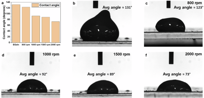
a Comparative graph of the average contact angles for pure EGaIn and PBU-EGaIn mixtures; Visual documentation of contact angles for (b) unaltered EGaIn; (c) PBU-EGaIn mixed at 800 rpm; (d) PBU-EGaIn mixed at 1000 rpm; (e) PBU-EGaIn mixed at 1500 rpm; (f) PBU-EGaIn mixed at 2000 rpm, elucidating the effects of shear mixing speed on the wettability of the composites.
To further investigate the interfacial interactions, dynamic contact angle measurements were conducted for both pristine EGaIn and the PBU-EGaIn composite on conventional glass substrates. The advancing contact angle, measured during the deposition of the droplet onto the substrate, remained relatively constant for both samples, even with increasing droplet volume. Pristine EGaIn exhibited an advancing contact angle of 143°, while the composite showed a lower value of 76°. This difference can be attributed to the influence of the PBU matrix on the surface energy of the composite. During the receding process, where the droplet is withdrawn from the substrate, a more pronounced distinction was observed. The receding contact angle of pristine EGaIn decreased significantly (from 143° to 1°) and at a faster rate compared to the PBU-EGaIn composite (from 66° to 14°) (Supplementary Fig. 3a). This discrepancy can be attributed to the presence of the PBU matrix, which encapsulates the EGaIn microdroplets and prevents direct contact with the substrate, thereby inhibiting the formation of an oxide layer35. This oxide layer, typically formed on the surface of pristine EGaIn, hinders the receding motion and leads to a more pronounced decrease in the contact angle. The observed differences in dynamic contact angles are further corroborated by the droplet shape analysis (Supplementary Fig. 3b)36. Pristine EGaIn exhibited a distinctive “sagging” phenomenon during receding, where the contact line remained pinned to the substrate due to the presence of the oxide layer, even as the droplet volume decreased. Conversely, the composite did not exhibit this sagging behavior, as the PBU matrix effectively encapsulates the liquid metal, preventing direct contact with the substrate and promoting stable interfacial contact. These findings highlight the crucial role of the PBU matrix in modulating the interfacial properties of the composite. By encapsulating the EGaIn microdroplets, the PBU matrix not only enhances the stability of the conductive network but also modifies the wetting behavior, preventing sagging and promoting more controlled spreading on the substrate. This improved interfacial stability can be advantageous for various applications in flexible and stretchable electronics, where reliable interfacial contact is essential for optimal performance.
The relationship between the resistance and strain levels of PBU-EGaIn composite
Upon the determination of the optimum EGaIn content and the precise mixing velocity, the capabilities of the composite were subject to rigorous evaluation. A singular test specimen, meticulously dimensioned to 30 mm by 10 mm, was subjected to a cyclic strain analysis, testing the material up to 135% strain—a figure proximal to the ultimate tensile strain limit of 145%. This specimen was securely mounted on a custom-engineered fatigue testing device, with terminal connections established with the probes of an LCR (inductance, capacitance, and resistance) meter to facilitate the acquisition of resistance data. Documentation of each strain increment was methodically performed as denoted in Supplementary Fig. 4, with the duration of each experimental iteration extending to 1500 s. In the quiescent state, the specimen presented an initial resistance value of 2.5 Ω. At the imposition of 50% strain, the resistance experienced a nominal increase to 2.6 Ω, a value that persisted steadfastly through the conclusion of the inaugural test sequence, therefore the relative resistance change (ΔR/R0) at 50% strain is extremely small (around 2%). Escalating the strain to 75% and subsequently to 100% correlated with a proportional augmentation in resistivity, registering values of 2.72 Ω and 2.75 Ω, respectively. At a high strain level of 135%, the resistance variation remained limited to an increment of ~0.5 Ω, which is considered a tolerable fluctuation within the realm of electrical conductivity, as illustrated in Fig. 3a. This minor increase in resistance can be attributed to the composite’s limited time to fully restore its percolated conductive network during the dynamic cyclic testing. Despite this dynamic behavior, the maximum resistance difference between the composite in a resting state and at full extension did not exceed 0.5 Ω, highlighting the composite’s exceptional mechanical stability and ability to maintain conductivity under demanding conditions. At this high strain level, the liquid metal filler deforms in conjunction with the polymer matrix, leading to the disconnection of some conductive paths and a consequent increase in resistance at the fully stretched position. Conversely, at lower strain levels, the EGaIn microparticles experience less significant deformation, preserving the continuity of most conductive pathways and ensuring more stable resistance. This distinction in behavior arises from the interplay between the deformability of the liquid metal filler and the viscoelastic properties of the polymer matrix.
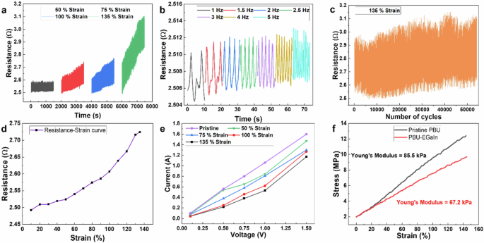
a Graphical representation of the composite’s conductivity under cyclic strain testing at incremental stretching intensities; (b) Conductivity persistence of the composite under cyclic strain at 135% elongation, across a spectrum of applied frequencies; (c) Longitudinal stability assessment over 50,000 cycles at a constant strain of 135%; (d) Resistance-strain curve of the PBU-EGaIn composite at 135% strain. (e) Characterization of current-voltage relationships in response to varying degrees of mechanical strain; (f) Stress-strain graphs of pristine PBU and PBU-EGaIn composite with calculated Young’s modulus.
Further investigations explored the impact of disparate stretching velocities on resistance variability. Given the requisite for stability in wearable sensor applications, irrespective of motion dynamics, the lateral velocity of the fatigue testing apparatus was varied to simulate real-world conditions and ascertain resistance metrics across different frequencies. The experimental outcomes revealed that resistance disparities between the unstressed and maximally strained states were insubstantial and exhibited independence from the imposed movement frequencies as depicted in Fig. 3b. Moreover, the endurance and uniformity of the composite were corroborated through a rigorous 50,000-cycle stretching regimen conducted at strains approaching the material’s limit (presented in Fig. 3c). Even after an extended series of tests, the resistance steadfastly hovered around 3.1 Ω. Analysis of the resistance-strain curve (Fig. 3d) reveals a minimal increase in resistance, rising by ~0.02 Ω per 10% strain. This corresponds to a relative resistance change (ΔR/R0) of only 0.8%, indicating excellent stability in electrical conductivity under tensile strain. Additionally, the interrelation between applied direct current (DC) voltage and measured current was scrutinized under diverse conditions to authenticate the insubstantial resistance deviations upon deformation (illustrated in Fig. 3e). These comprehensive scientific inquiries affirm the superior conductive performance of the PBU-EGaIn composite, significantly bolstering its applicability in the domain of soft electronics, where the juxtaposition of electrical integrity and mechanical suppleness is of paramount importance. To further characterize the mechanical behavior of the PBU/EGaIn composite, tensile tests were conducted to assess its stress-strain relationship. As illustrated in Fig. 3f, the composite exhibits a Young’s modulus of 67.2 kPa, indicating its flexibility and compliance. This value falls within the range typically observed for polymer composites used in flexible electronics applications. The stress-strain curve also provides insights into the force required to achieve a specific level of strain. To stretch the composite to 100% strain, ~7.6 MPa of stress is necessary. This value reflects the composite’s ability to withstand substantial deformation without undergoing fracture, a crucial characteristic for flexible and stretchable electronics. For comparison, the stress-strain behavior of the bare PBU (without EGaIn) is also presented in Fig. 3f. The bare PBU exhibits higher stress values at corresponding strain levels, indicating that the incorporation of the EGaIn filler reduces the overall stiffness of the composite. This softening effect can be attributed to the presence of the liquid metal, which disrupts the polymer chain interactions and enhances the material’s flexibility. These findings highlight the tunability of the mechanical properties of the PBU/EGaIn composite. By adjusting the composition and processing conditions, the mechanical behavior can be tailored to meet the specific requirements of various applications in flexible and stretchable electronics.
The mechanical properties of the PBU matrix are strongly influenced by the molecular weight of the base polymer. Increasing the molecular weight generally leads to enhanced mechanical performance due to a higher number of chain entanglements, which act as physical crosslinks and improve the material’s resistance to deformation and fracture. Higher molecular weight PBU exhibits increased tensile strength, allowing the material to withstand greater tensile forces before breaking. It also has enhanced toughness, enabling the material to absorb more energy before fracturing. Additionally, higher molecular weight PBU has a higher glass transition temperature, meaning the temperature at which the material transitions from a glassy to a rubbery state increases. This is because longer polymer chains have reduced mobility, requiring more thermal energy to induce segmental motion. However, increasing the molecular weight also has some drawbacks, as the increased chain length and entanglements lead to higher viscosity, which can hinder the melt flow of the polymer during processing. This can make it more challenging to mold, shape, or extrude the material. In this study, we utilized Krasol HLBH with a molecular weight of 2100 g/mol, chosen because it offered a good balance of desirable mechanical properties and processability. It provided sufficient tensile strength and toughness for the intended application while still allowing for relatively easy processing and integration with the liquid metal.
Thermal performance of PBU-EGaIn composite at different stretching conditions
The thermal characteristics of the PBU-EGaIn composite, specifically in its role as a stretchable electrode, were subjected to thorough scientific examination. The phenomenon of Joule heating, a principle where heat generation is the result of electrical current traversing through a conductive material, was exploited in these investigations. The application of direct current for heating, as well as for the concurrent measurement of the ensuing electrical current, was accomplished using a sophisticated source meter. A temperature of 120 °C was identified as the optimal thermal benchmark for the composite, a point at which the Diels–Alder reaction is known to proceed with requisite efficiency to initiate the self-healing process within the PBU matrix, as substantiated by prior research37. The composite’s temperature distribution during Joule heating was meticulously recorded using a high-precision digital multimeter and an advanced infrared-ray camera. Upon the administration of a 4.5 V direct current, the heating rates across the composite were observed to be prompt, with samples at unaltered, 50%, and 100% strain levels reaching the desired temperature threshold within 2 min. In contrast, the sample subjected to nearly its maximum strain capacity exhibited a marginally extended heating duration, approaching 3 min to attain the 120 °C threshold (Fig. 4a). To assess the heat transfer ability of the PBU/EGaIn composite, we calculated its Joule heating power and volumetric energy density. The Joule heating power (P), representing the rate of electrical energy conversion into heat, was calculated using the Eq. (4):
where V is the applied voltage and R is the resistance. For the unstrained composite, the calculated Joule heating power was 8.1 W. To further quantify heat generation, we determined the volumetric energy density (Q) as Q = P/V, where V is the volume of the composite. Given the sample dimensions of 30 mm × 10 mm × 0.13 mm, the calculated volumetric energy density was 0.21 W/mm3. While these calculations provide valuable information about heat generation, it is important to consider heat dissipation, which is influenced by conduction, convection, and radiation. The thermal conductivity of the composite was measured to be 8.935 W/m ∙ K, and its specific heat capacity is 0.642 J/g ∙ K. These values are crucial for understanding heat dissipation within the composite. Furthermore, a subsequent experimental series employed a stepwise increase in voltage intensities, beginning from 0.5 V and escalating to 3.5 V. Each voltage increment was applied only after it was ascertained that the preceding voltage could no longer induce a significant thermal rise. These trials demonstrated that the extent of mechanical deformation was proportional to the time required to achieve the heating target. Notably, a specimen without any strain required ~1100 s to reach the designated temperature (Fig. 4b), with this timeframe progressively lengthening, reaching 1210 s for the specimen subjected to the most extensive strain (Fig. 4c–f). These rigorous experimental evaluations confirm the PBU-EGaIn composite’s proficiency in Joule heating, showcasing its capability to respond thermally in a prompt and controlled manner, a property essential for applications necessitating quick thermal modulation in tandem with flexible material properties. The ability to precisely manage thermal response is imperative for the activation of self-healing mechanisms within smart materials, offering a robust solution for the maintenance and longevity of soft electronic systems.

Constituent composition at 55% and mixed at 2000 rpm. (a) Graph illustrating the heating kinetics of the composite subjected to a constant 4.5 V DC across varying degrees of strain. Sequential heating curves of the composite at progressive strain levels with incrementally increasing applied voltages: (b) Unstrained; (c) 50% strain; (d) 75% strain; (e) 100% strain; (f) Near-fracture strain of 135%.
Infrared (IR) thermographic imaging was utilized to scrutinize the distribution of heat across the composite thin film as a function of its mechanical strain, detailed in Fig. 5. Each column represents a specific strain level, with the upper, middle, and lower rows capturing distinct thermal states. The top row images illustrate the junctures at which the hottest zones approximate the target temperature, while the middle row images document the attainment of 120 °C at the sample’s core—a temperature conducive to the Diels–Alder reaction, which is central to the self-healing process of the composite. The bottom row images reflect the thermal signature after 1 min of heating, under an applied voltage of 3.5 V for all conditions. Initially, in the unstressed state of the composite (sample’s length = 18 mm), an even heat distribution was observed across the surface, with a minimal temperature gradient due to the high density of the metallic filler uniformly embedded within the polymer matrix. This homogeneity ensures efficient electron mobility and, consequently, uniform Joule heating. Upon elongation of the sample to 100% and 135% of its original length (extending from 18 mm to 36 mm and 42 mm, respectively), a marked deviation in thermal distribution was observed. The areas adjacent to the voltage application sites manifested intensified IR emission, evidenced by a darker appearance in the central region, indicative of cooler temperatures due to its increased distance from the DC source. This effect was most pronounced at a strain of 135% (total length = 42 mm), where the thermal disparity reached up to 10 °C. In comparison, the unstrained and 100% strained samples (total length = 36 mm) exhibited thermal differentials of merely 1 °C and 5 °C, respectively. Such temperature variations can be explicated by the elongated conductive pathways, characterized by a diminished surface contact area and more extensive liquid bridges within the stretched composite. These altered geometric configurations lead to increased resistance to electron flow, particularly impacting the central region due to its relative remoteness from thermoelectric influence38. Consequently, over a time span of 60 s, the strained specimens exhibited significant temperature deltas, most notably the sample at 135% strain, which only managed to attain a peak temperature of 91.7 °C.

a Infrared images captured at the instance when the highest temperature regions of the samples attained ~120 °C; (b) Infrared images documenting the moment when the central area of the samples reached a temperature proximate to 120 °C; (c) Infrared images recorded subsequent to a 60-s duration of heating, with an applied voltage of 3.5 V across the samples.
In the domain of wearable technology, high endurance, and intrinsic self-healing capabilities are imperative to address and rectify damages such as incisions39,40,41,42. To quantitatively evaluate the self-healing efficacy of the PBU-EGaIn composite, a sequential IR thermal analysis was conducted. This analysis comprised three distinct investigative conditions, each represented in separate columns of Fig. 6: the initial intact state, the subsequent state following incision, and the final state after the self-healing process. Upon making an incision in the composite film with a razor blade, a marked decrease in temperature was discernible in the IR images, particularly pronounced when the composite was subjected to mechanical strain. This phenomenon was characterized by an increased thermal footprint at the site of the damage, indicating a significant deviation from the composite’s nominal temperature, which was adeptly identified by the IR camera’s coldest point detection feature (blue crosshairs, as depicted in the middle column of Fig. 6). To initiate the self-healing process, the damaged composite samples were restored to an unstressed state and a DC voltage was applied. This electrical input triggered the outflow of liquid metal droplets from the matrix due to the material’s inherent high surface tension. Realigning the severed interfaces facilitated the re-establishment of electrical conductivity through the conductive pathways43. Subsequent heating mediated the melting of the polymeric substrate adjacent to the cut, thereby re-liquefying the polymer and enabling it to bridge the incision, effectively reconstituting the composite’s integrity. Post-healing, the composites exhibited remarkable resilience, maintaining functional integrity under strains of 100% and 135%, as demonstrated in the second and third rows of Fig. 6, respectively. The self-healing process was underpinned by the Diels–Alder reaction, which within the PBU matrix, utilizes furan groups from the diol component and maleic anhydride from the BMI to form reversible cross-links. The thermal and chemical conditions favorable for this self-healing reaction, specifically the retro-Diels–Alder reaction, have been thoroughly characterized in the referenced literature44,45,46,47, providing a robust scientific foundation for the composite’s reparative abilities. To initiate the self-healing process, the disconnected conductive path was carefully brought back into contact, and a small pressure was applied to ensure good interfacial contact. Due to the higher resistance at the rejoined interface, localized Joule heating occurred when a DC current was passed through the composite48. This localized heating is essential to elevate the temperature in the damaged region to 120 °C, which is necessary to activate the Diels–Alder reaction and initiate the self-healing process in the PBU matrix. While localized heating might raise concerns about potential thermal damage to surrounding components, several factors mitigate this risk. Firstly, the applied voltage (4.5 V) and the duration of current flow are carefully controlled to limit the extent of heating and prevent excessive temperature rise in areas beyond the repair zone. Secondly, the PBU matrix itself has a relatively low thermal conductivity, which helps to confine the heat to the damaged region and minimize its spread to surrounding areas. Thirdly, the use of the same conductive material (EGaIn) for both sides of the rejoined interface minimizes thermal and energy waste compared to a situation where two dissimilar conductors are in contact. Furthermore, the localized nature of the heating offers a significant advantage: it ensures that the temperature required for the Diels–Alder reaction is reached specifically at the damaged site, promoting efficient and rapid self-healing of the PBU matrix without compromising the integrity of adjacent components49. This signifies that our electrodes are capable of autonomous self-healing.
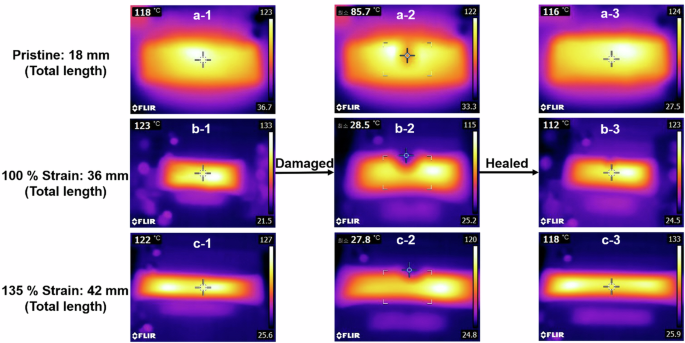
a In the unaltered state; b Under 100% strain; c At the near-fracture strain of 135%. Columns one, two, and three depict the composite sequentially in its pristine state, following the infliction of damage, and after undergoing the self-healing process, respectively.
High-resolution digital imaging was conducted concurrently with thermal analysis to meticulously document the surface topography of the samples, thereby enabling an in-depth morphological evaluation subsequent to the recovery process, as depicted in Supplementary Fig. 5. With regard to the composites’ elasticity, the self-healed specimens exhibited unimpaired retention of their original strain characteristics. This conservation of mechanical robustness intimates that the self-healing mechanism entails the strategic cleavage of three pi bonds within the polymeric lattice—specifically, two pi bonds from the diene component and one pi bond from the dienophile—during the [4+2] cycloaddition reaction. The process culminates in the formation of two novel sigma bonds while concurrently regenerating an additional pi bond. Such intricate molecular reconfiguration is critical for reinstating the composite’s inherent tensile properties, reflecting the efficacious restoration of the polymer network after damage. The intricacies of this self-healing response have been expounded in the scientific literature as indicated in ref. 50.
The self-healing capability of PBU-EGaIn composite
Beyond the topological assessment, the conductive and thermal properties of the self-healed composite were rigorously evaluated. The composite was subjected to two distinct damage modes: a single intersecting incision and multiple intersecting incisions. To precisely evaluate the conductivity of the composite, cyclic strain tests at 100% strain were conducted on each sample under three conditions: pristine, after healing from a single incision, and after healing from multiple incisions. This comprehensive analysis allowed for a thorough assessment of the composite’s ability to maintain electrical conductivity after experiencing various degrees of damage and subsequent self-healing. From an electrical standpoint, in its pristine state, both the minimal and maximal resistance values exhibited a gradual increase throughout the testing period; nonetheless, the range between these values remained stable (as shown in Fig. 7a). Conversely, after undergoing the self-healing process, the PBU-EGaIn composite maintained a consistent resistivity, irrespective of being in a relaxed state or fully elongated. With a single incision, the resistance discrepancy was less than 0.5 Ω, while for multiple incisions, it was 1.5 Ω. Even in the scenario of multiple incisions, post-recovery, the absolute maximum resistance observed was only 4 Ω, indicating the material’s continued excellent conductivity (as illustrated in Fig. 7b, c). Concerning the thermal conductivity, both one-time damaged and multiply damaged healed specimens were able to reach the critical temperature required to initiate the Diels–Alder reaction. However, this process was protracted, taking ~5 min. Voltage step tests were performed for both types of damaged conditions: the single incision required 1250 s to reach the desired thermal state, while the multiple incisions required about 1400 s (depicted in Fig. 7d, e). Furthermore, the efficiency of the healing process was quantitatively analyzed across varying degrees of sample elongation. It was observed that the healing efficacy diminished proportionally with increased sample length. This can be attributed to the dispersion of the same quantity of liquid metal over an augmented surface area, which inherently reduces the density of the conductive network, thereby impacting the composite’s capacity for heat generation and, consequently, its ability to facilitate self-repair (as indicated in Fig. 7f). This inverse relationship between stretching magnitude and healing proficiency highlights the challenges in maintaining healing efficiency in composites subjected to extensive mechanical deformation.
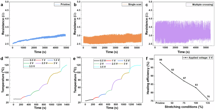
a Electromechanical performance under cyclic strain in its pristine state; b Electromechanical behavior post-recovery from a single incision; c Electromechanical response following restoration after multiple intersecting incisions (The stretching threshold was 100% of the sample’s original length). Assessment of the thermal recuperation post-self-healing from (d) A single incision; e Multiple intersecting incisions. f Comparative analysis of self-healing efficiency across varying extents of sample elongation.
The pattern-ability of PBU-EGaIn composite
The PBU-EGaIn composite demonstrated the capability to be precisely patterned into specific micro-sized configurations, which is a pivotal technological advancement. Employing a stencil mask technique, uniform dots with diameters of 50 µm were successfully fabricated, which holds significant promise for applications in print circuit board (PCB) manufacturing, as evidenced by the creation of a 4 × 4 dot array with equidistant spacing (refer to Fig. 8a). Subsequent figure, 8b, c, illustrate the formation of a cross and a right angle, each with a meticulous thickness of 100 µm. The edges of these patterns were remarkably defined, with the fabricated surfaces exhibiting a high degree of smoothness. Moreover, the stencil technique proved adept at producing complex designs, as demonstrated by the defect-free, intricate pressure sensor pattern, which included exceptionally thin lines with no overlap (shown in Fig. 8d). The clarity of the patterning was further pronounced under mechanical strain; fine individual lines retained their distinct separation, as shown in Fig. 8e.
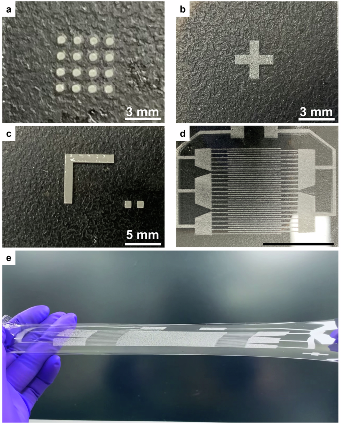
a A uniformly spaced dot matrix suitable for PCB applications; b A precisely formed cross symbol; c An accurately angled right symbol; d An intricate pattern adeptly printed onto the substrate (indicated by a 10 mm scale bar); e The detailed pattern displayed under tensile strain.
The composite’s autonomous self-healing capability was rigorously evaluated across a spectrum of intricate geometrical configurations, showcasing consistent recovery irrespective of the complexity or number of inflicted damage sites. This validation was methodically conducted through controlled experiments wherein two composite specimens, featuring predetermined patterns responsible for conveying electric signals to a light emitting diode (LED), underwent deliberate damage at specified locations (refer to Supplementary Fig. 6, first row). Subsequent analysis revealed that following damage, as evidenced by the LEDs ceasing to illuminate (Supplementary Fig. 6, second row), the self-repair mechanism efficiently reinstated the conductive pathways in both instances, thereby facilitating the reactivation of the LEDs (Supplementary Fig. 6, third row). Further elucidation of the healing dynamics was pursued using a field emission scanning electron microscope (FESEM), which provided visual insights into the closure of a gap initially measuring ~60 µm in width (Supplementary Fig. 7a). The observed closure of the gap progressed discernibly, culminating in complete sealing, with the resultant mend being readily discernible (Supplementary Fig. 7b–d). Additionally, atomic force microscopy (AFM) analysis quantified the reduction in dimensions of the incision post-healing, revealing a decrease in both width and depth of the composite from ~5 µm to nearly 2 µm, and from around 3 µm to ~0.5 µm, respectively (Supplementary Fig. 7e). To provide a more comprehensive understanding of the self-healing process, a time-lapse video with a detailed description has been included as supplementary material (Supplementary Video 1). This video demonstrates the following stages: A cut is introduced into the composite, disrupting the conductive network and interrupting electrical conductivity, visually confirmed by the cessation of current flow and the extinguishing of an LED. The separated parts of the composite are brought into contact and a DC power supply is connected, initiating the self-healing process, with the liquid metal (EGaIn) rejoining to re-establish the conductive pathway. The rejoined interface exhibits higher resistance, leading to localized Joule heating, which is crucial for raising the temperature of the damaged region to ~122 °C, as confirmed by measurements using a thermal imaging camera. The elevated temperature (122 °C) exceeds the melting point of the PBU matrix. To ensure intimate contact between the separated regions and facilitate efficient rejoining of the polymer chains, a weight is applied to the damaged area. As the PBU matrix cools and solidifies, the composite regains its structural integrity and electrical conductivity, visually confirmed by the re-illumination of the LED, indicating the successful restoration of the conductive pathway. Further examination of the healed composite reveals that while a scar may be visible from the top view, no disconnection is observed when the covering polymer is bent (Supplementary Video 2). This indicates that the polymer chains have fully rejoined, restoring the mechanical and electrical integrity of the composite. This time-lapse video provides a clear and detailed visualization of the self-healing process in the PBU/EGaIn composite, highlighting its ability to recover both electrical and mechanical functionality after damage. The refined morphological features and high-resolution patterning observed in the composite can be attributed to the altered surface tension of the PBU-EGaIn compound. This alteration arises from the encapsulation of the liquid metal component within the polymeric matrix, resulting in a transition from an oxide-encased state to one where the polymer matrix predominantly encapsulates the alloy, thereby influencing its surface energy properties51. The proficient patterning capabilities demonstrated by the PBU-EGaIn composite represent a significant advancement in the realm of stretchable circuits, offering a versatile and practical material solution for sophisticated electronic applications.
Practical application of the PBU-EGaIn composite as a wearable sensor device
The PBU-EGaIn composite, a synthesis of PBU and employing EGaIn, exhibits superlative properties that make it an exemplary candidate for applications in wearable electronics due to its remarkable elasticity and stability. Its performance as a wearable motion sensor was systematically evaluated, capitalizing on its potential to monitor and analyze human movement with high fidelity. The composite was strategically affixed to joints such as fingers, wrists, and knees, regions that commonly experience a range of motion. The quantification of motion was facilitated through the measurement of relative capacitance changes (C/C0) employing two extrinsic conductive leads to ensure consistent and secure connectivity to the LCR meter. The application of the patterned composite for sensing tasks was particularly advantageous in instances necessitating compact sensors. During the digit articulation test, the capacitance variation between flexed and extended digit positions was minor (C/C0 ≈ 8%) indicating the composite’s nuanced sensitivity to subtle movements, as shown in Fig. 9a. In contrast, actions that involve broader ranges of motion, such as wrist rotation, elicited more pronounced capacitance signals, demonstrating the sensor’s ability to detect varying degrees of articulation. The ultrathin nature of the patterned sensor, highlighted in the inset of Fig. 9b, is not merely an aesthetic advantage but also functionally crucial. It ensures that the sensor is non-intrusive and harmonizes with the wearer’s natural movements, a pivotal characteristic for wearable technology to be truly integrated into everyday use without impeding the user. For larger joints like the knee, which undergo more extensive motion, an expanded sensor footprint was necessary to cover the area adequately and capture the full dynamic range of movement. The signals acquired from such extensive motion were proportionately larger, reflecting the sensor’s ability to scale its sensitivity with the amplitude of the subject’s activity (Fig. 9c). Furthermore, the prompt and precise capacitive response to the wrist’s movement, as illustrated in Fig. 9d, showcases the sensor’s exceptional responsiveness—a critical aspect in real-time motion detection and feedback. This responsiveness is a testament to the composite’s ability to rapidly modulate its electrical properties in synchronization with physical deformations, a quintessential attribute for the development of advanced and intuitive wearable electronics.

a When adhered to a finger; b Conforming to the contours of a wrist; c Positioned on a knee; d Capacitance fluctuation correlated with the wrist’s flexion at variable velocities (Inset: Photographic depiction of the sensor deployed in situ).
Recycle ability of PBU-EGaIn composite to re-achieve EGaIn droplets
Despite the PBU-EGaIn composite’s remarkable flexibility and straightforward self-healing capabilities, it was acknowledged that in certain scenarios the composite may not be suitable for direct reuse following damage. Consequently, a meticulous recycling protocol was devised to segregate and reclaim the liquid metal, leveraging its near-complete recyclability52. The reclamation process encompassed two principal stages. The initial phase involved the thermal dissolution of PBU: the fully cured composite was subjected to heat treatment at 140 °C in the presence of Methyl ethyl ketone (MEK). This procedure facilitated the depolymerization of PBU, aligning with the retrograde Diels–Alder reaction, whereby the crosslinked network decomposed into distinct imide and furan entities50. Notably, this step did not compromise the integrity of the conductive alloy, which boasts a melting point substantially exceeding 2000 °C, thus remaining unaffected53. Subsequent to the dissolution of the polymeric matrix, the isolated EGaIn particulates underwent a series of MEK washes, followed by sonication to extricate any lingering polymer residues. Once liberated into the environment, the liquid metal droplets reinstated their inherent high surface tension, a characteristic that is particularly pronounced under extreme pH conditions54,55. For the oxide layer removal and reinstatement of the metal’s original interfacial tension, a 1 M sodium hydroxide (NaOH) solution was employed, effectively stripping the oxide layer. This facilitated the coalescence of the dispersed metal particles into a singular, cohesive drop, a transformation depicted in Supplementary Fig. 8. This systematic recovery process underscores the sustainability aspect of the PBU-EGaIn composite, offering an environmentally considerate option for the lifecycle management of materials used in stretchable electronics.
Our investigation entailed a comprehensive comparative analysis aimed at benchmarking the performance characteristics of the PBU-EGaIn composite developed in this study against existing research paradigms. The examination encompassed a spectrum of composite configurations, each designed to imbue the material with specific attributes such as stretchability, minimal resistance variation under mechanical strain, self-healing capabilities, and recyclability, as delineated in Table 156,57,58,59,60,61,62,63,64. Notably, the composite we developed stands out for its unique amalgamation of these properties, a feat unparalleled by preceding materials. Across a range of performance metrics, our composite consistently demonstrated either superior or commensurate performance when juxtaposed with previous research findings. Furthermore, the material exhibits an exceptional ability for autonomous self-healing, particularly when deployed as a heating element, a distinctive characteristic not observed in earlier studies. We are confident that the innovation presented in this research represents a significant breakthrough in addressing a critical challenge inherent in conventional stretchable soft electronics.
Discussion
In conclusion, this study has culminated in the development of an innovative PBU-EGaIn composite characterized by remarkable stretchability, minimal resistance variation under mechanical strain, superior stability, autonomous self-healing, and recyclability. The material demonstrates the ability to maintain electrical conduction with minimal resistance values, not exceeding 4 Ω, under various degrees of mechanical strain up to 135%. The composite’s thermal response is noteworthy; it efficiently attains temperatures of up to 120 °C in a short time frame. Reaching this critical thermal threshold triggers the Diels–Alder reaction, which underpins the composite’s autonomous self-healing process, allowing for the restoration of the PBU layer’s integrity after damage. The repaired areas regain functional normalcy, a testament to the exceptional self-healing efficacy of the material. In addition to its restorative properties, the PBU-EGaIn composite has been engineered to support precise patterning through a simple stencil mask technique, attributed to its reduced surface tension. This capability enhances its suitability for intricate designs required in advanced electronic applications. When leveraged as a motion detector, the composite performs admirably, demonstrating high sensitivity and responsiveness, effectively detecting subtle movements. Furthermore, the composite boasts high-resolution patterning capabilities, capable of sensing even the slightest movement with pronounced responsivity—a critical feature for wearable technology. The practical implications of this are profound, opening avenues for the integration of the PBU-EGaIn composite into the burgeoning field of soft, wearable electronics. In instances where the material does not manifest self-healing properties, a strategic two-step recycling protocol has been established. This process efficiently recovers the valuable EGaIn, underscoring the sustainability of the composite by ensuring that the constituent materials can be reused, thereby contributing to the principles of circular economy within material science.
Methods
Materials
Hydrogenated hydroxyl-terminated polybutadiene (Krasol HLBH-P 2000, Mn = 2100 g/mol) was procured from Cray Valley. Isophorone diisocyanate (IPDI) and dibutyl dilaurate (DBTDL), the reactive components and catalyst, respectively, were sourced from Sigma-Aldrich. MEK utilized as the solvent in the synthesis process, was acquired from Daejung Chemicals. A customized diol, synthesized from glycerol 1,2-carbonate and furfuryl amine obtained from TCI Chemicals, served as the chain extender. Bis(3-ethyl-5-methyl-4-maleimidophenyl)methane (BMI) from TCI Chemicals was employed as the self-healing agent in the formulation of the PBU. EGaIn alloy, the conductive filler, was also purchased from Sigma-Aldrich. Sodium hydroxide (NaOH) 1 M was purchased from Daejung Chemicals to agitate small particles of EGaIn into bulk EGaIn.
Synthesis of diol
The diol, pivotal in enabling the polyaddition reaction between the polyol and IPDI, was synthesized by reacting 13.1 g of glycerol 1,2-carbonate with 10.79 g of furfuryl amine. The reactants were combined and subjected to magnetic stirring at 60 °C for 3 h within an oil bath.
Preparation of PBU Substrate
To synthesize the PBU matrix, 4 g of HLBH-P 2000, 0.43 g of the prepared diol, 0.89 g of IPDI, and 4.5 g of MEK were mixed with 4 drops of DBTDL as the catalyst. This mixture was then stirred magnetically at 60 °C for 2 h. Subsequently, a quantified amount of BMI was introduced to the reaction mixture to complete the PBU synthesis. The stirring continued for an additional 30 min under the same conditions. The resultant PBU mixture was then subjected to spin coating at 1500 rpm for one min to form a thin film, which was subsequently dried at 60 °C overnight, creating the substrate for the conductive composite.
Fabrication of PBU-EGaIn composite
For the fabrication of the PBU-EGaIn composite, bulk EGaIn was first subjected to probe sonication in ethanol using a VCX750 ultrasonic processor (Vibra-Cell) for 30 min. The sonication regimen involved multiple cycles, alternating between 3 s of sonication and 3 s of rest, spanning a total of 3 h. Following sonication, the resultant smaller EGaIn droplets were integrated into the PBU mixture at various ratios. The composite mixture then underwent planetary mixing using a paste mixer (Thinky Supermixer, Japan) for 2.5 min before being applied to the bare PBU substrates via spin coating and allowed to cure at ambient temperature. A detailed schematic of the synthesis process can be found in Supplementary Fig. 9. For patterning, the PBU-EGaIn composite was applied to the PBU substrate using stencil masks. The patterning process entailed placing a mask, designed using AutoCAD software and bearing predefined shapes, onto the substrate. The composite was then distributed uniformly using a rubber putty knife, carefully maintaining an optimal angle to avert leakage. This step was performed expeditiously to ensure proper curing of PBU at room temperature. Following this, the stencil mask was swiftly and cleanly removed, leaving behind the desired pattern. To enhance adhesion between the PBU substrate and the composite, an Ar/O2 plasma treatment was administered to the PBU surface prior to patterning.
Characterization of materials and devices
The samples were meticulously examined utilizing an optical microscope (OM; Model DM2700m, Leica Microsystems). Field emission scanning electron microscopy (FESEM; SEMIRON 5000, SERON TECHNOLOGIES INC., South Korea) was employed to scrutinize the surface morphology of the fabricated circuits. For quantitative assessment of the electrical properties, resistance and capacitance were accurately measured with an LCR meter (Model LCR 6100, GW Instek). Copper wires were employed as conductive pathways to relay capacitance signals from the composite to the LCR meter for accurate measurement. XRD analyses to discern the chemical composition of both the pristine PBU and the composite were performed using an advanced XRD system (Model D8 ADVANCE, Bruker AXS GmbH). The hydrophilic nature of the composite surfaces was evaluated by measuring the water contact angle with a precision goniometer (Model Phoenix-10, Surface Electro Optics). The endurance of the composite under repetitive strain was rigorously tested using a custom-engineered stretching apparatus. Thermal response and distribution characteristics were scrutinized through the use of a digital multimeter (Model 34461A, Keysight Technologies) and an infrared (IR) camera (Model FLIR E8, Teledyne FLIR LLC). AFM analyses to map the surface topology were conducted with an optical microscope equipped with a 10× objective lens, and surface data was diligently recorded with a system from Park Systems. For the electrical characterization and Joule heating studies, the samples were precisely cut into oblong shapes measuring 30 mm × 10 mm. In preparation for the wearable trials of the PBU-EGaIn composite as motion detectors, the specimens were trimmed to suitable dimensions and affixed to various body parts utilizing biocompatible double-sided adhesive tape.


Responses