Balancing aesthetics and efficiency of coloured opaque photovoltaics

Introduction
The mass deployment of photovoltaics (PV) is essential to the energy transition1 but can conflict with other land uses, especially in densely populated regions2,3. Integrating PV modules into buildings and infrastructure avoids additional land use during PV deployment, but has challenges as PV modules should serve as both power generators and construction elements4,5. Conventional PV modules have high power conversion efficiencies (PCEs), but often lack aesthetic versatility in terms of colour, size and shape, limiting their acceptance in built environments6. Aesthetics have a vital role in the decisions of architects and building owners, necessitating the development of visually appealing PV modules7,8.
PV elements can be specialized for integrated applications9 such as coloured opaque PV10, coloured translucent PV11 and neutral-coloured translucent PV12. Coloured opaque PVs can be integrated into roofs, facades, vehicles and transportation infrastructure (Fig. 1a), which could facilitate further PV deployment in the built environment. Coloured opaque PVs can maintain high PCEs despite some visible light being reflected for colour creation13,14. Single-junction, opaque solar cells, with optimal reflection spectra, can theoretically achieve PCEs of more than 29% under the Shockley–Queisser limit condition for most colours13, whereas ones based on a real crystalline silicon (c-Si) solar cell can achieve more than 22%15 (Fig. 1b). For coloured opaque PV modules, the estimated maximum PCEs (Fig. 1c), which are practically achievable, range from 19.81% to 23.51% for various chromatic colours, whereas PCEs range from 16.18% to 24.01% for neutral colours (Supplementary Note 1). Therefore, it is reasonable to infer that for a coloured PV module featuring commonly used colours, a PCE of ~22% is achievable, provided that the module exhibits near-ideal optical properties and commercial solar cells reach PCEs exceeding 26%.

a, Applications for coloured opaque photovoltaics (PV) modules. b, Theoretical maximum power conversion efficiencies (PCEs) of coloured solar cells as functions of perceptual colour lightness (L*), based on ref. 15. c, The simulated PCE of a coloured PV module with a colour in the Macbeth ColorChecker chart. The coloured PV is made by increasing the reflectance confined within 400–700 nm of a silicon solar cell with a PCE of 26.3% and an 8% cell-to-module loss is considered. The colours are determined by ‘BabelColor Avg’ spectrum and reproduced using sRGB values95, and the colour lightness value in CIELAB colour space is also presented, using D65 as an illuminant (Supplementary Note 1). d, Illustration of opaque-coloured PV modules made by adding a colouring layer to modify the spectral properties of conventional black PV modules, presenting either chromatic or achromatic colours.
Although some emerging solar cell materials can be made intrinsically colourful, their low PCEs and short lifetimes make them still unviable choices for large-scale integrated applications16,17,18. Instead, the spectral engineering of high-efficiency, reliable PV modules, without altering solar cells, tends to be the most popular method for making PV elements more visually pleasing10. This process involves adding a colouring layer upon black solar cells, enabling them to reflect visible light and thus be coloured, either chromatic (for example, blue, green or red) or achromatic (for example, grey or white) (Fig. 1d). This technology gives coloured PV modules the durability, high PCE and established production methods of well-established PV materials such as c-Si19,20. However, reported coloured PV modules are often either unsatisfactorily coloured or relatively inefficient, and further technological advances are hindered by obstacles such as the inappropriate use of colourants and the lack of design optimization10,21.
In this Perspective, we propose benchmark methods and guidelines for the future advancement of coloured opaque PV modules and discuss the technical specifics of coloured opaque PV technologies. We compare the advantages and disadvantages of the most commonly used colouring layer technologies, which have been reported at commercial scales in real building-integrated applications, and consider the potential for colouring layer materials which have been reported at the laboratory scale. We provide a design method for creating a PV module with a desired colour and minimized PCE loss and describe performance metrics, which all coloured PV studies should report to enable comparison of different technologies as this field expands.
Coloured opaque PV technologies
A typical PV module, such as c-Si, comprises solar cells adhered to a proactive front cover (such as glass) and a backsheet using polymer encapsulants22. The colouring layer can be incorporated in various ways: coated on glass cover surface19, mixed with the encapsulant or inserted as a separate polymeric foil23 or applied directly to solar cell surface24 (Fig. 1d). Thin-film solar cell materials, such as perovskite, are directly deposited on glass substrates, limiting most colouring layer placement to pre-coating the glass interior or post-coating the exterior25,26.
To be efficient and commercially relevant, there are three requirements that coloured opaque PV need to meet (Fig. 2A). First, to guarantee a high PCE, the colouring layer should selectively reflect specific visible light to create a targeted colour under natural sunlight and, second, be highly transparent to other solar radiation that can be absorbed by solar cells14 (Fig. 2A). Third, considering the size and cost of commercial PV modules27, the colouring layer needs to be producible on a large area (for example, larger than 1.5 m2) at a low cost (for example, less than US$20 m−2). In addition to these requirements, there are also concerns over material toxicity and colour stability during prolonged outdoor exposure that need to be addressed. As there has been no previous demand for colouring materials to simultaneously meet these requirements, there is not yet a colouring layer for coloured PVs that fits all of these criteria fully. Instead, prevailing practice is to use the materials and techniques detailed in this section.
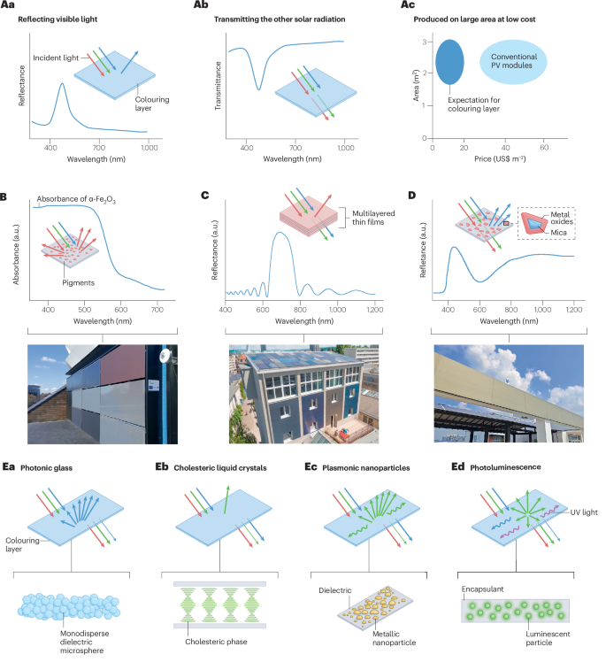
A, Desired properties of materials for colourizing photovoltaic (PV) modules. B–D, Three representative colouring materials that have been used in coloured opaque PV modules with area >1 m2, including their optical properties (top) and the photographs of corresponding PV modules in outdoor applications (bottom): conventional inorganic pigments (part B); multilayered dielectric thin films (part C); and interference pigments with multilayered structure (part D). E, Other emerging colouring materials used in coloured PV modules, including photonic glass, cholesteric liquid crystals, plasmonic nanoparticles and photoluminescent materials. a.u., arbitrary units; UV, ultraviolet. Photograph in part B reprinted with permission from ref. 34, EU PVSEC. Photograph in part C reprinted with permission from ref. 19, Elsevier.
Inorganic pigments
Inorganic ceramic pigments are widely used in industrial applications owing to their low cost (mostly US$1–10 kg−1) and high durability (essentially permanent unless mechanically damaged)28. Coloration results from their chemical structures, which enable them to partially absorb visible light, whereas the non-absorbed light is scattered. For instance, iron oxide (α-Fe2O3), a commonly used red pigment, has a bandgap of ~2.1 eV, resulting in the absorption of blue and green light and the diffused reflection of red light29 (Fig. 2B). If a pigment (for example, titanium white) does not absorb but evenly scatters all wavelengths of visible light (λ ~400–700 nm), it appears white. Therefore, conventional inorganic pigments cannot meet the second requirement outlined in Fig. 2A.
When applied to the colouring layer of PV modules, the parasitic absorption of coloured pigments or non-selective reflection of white pigments inevitably leads to higher PCE loss, which ranges from about 10% to 70% depending on the type of pigments and printing opacity30,31. As coloured pigments cause parasitic absorption, white pigments — which have negligible absorption — have been demonstrated to enable brighter colour and lower PCE losses than green and red ones32. Although not yet extensively studied, the pigment particle size is theoretically another crucial factor influencing the performance, as it affects both light scattering and absorption efficiency33. Therefore, by optimizing the material choice and sizes of inorganic pigments, the PCE of coloured PV by this method may be further improved.
Despite this inherent limitation, colour glazes with inorganic pigments can be easily deposited by screen printing or digital inkject printing and sintered to form durable and reliable colouring layers10. This enables large-scale coloured PV modules that have already been practically implemented6. To preserve adequate power generation capacity, most coloured PVs based on this approach typically exhibit relatively dark tones, such as grey, terracotta and greyish blue34 (Fig. 2B, bottom).
Multilayered dielectric thin films
Overcoming the PCE and colour lightness limitations of traditional pigments requires novel colouring materials, which create colour by specific micro–nano structures and feature negligible solar absorption35. Efforts to achieve these goals have been mainly focused on multilayered dielectric thin films, which can selectively reflect a small portion of visible light while transmitting most sunlight (Fig. 2C) and can be coated on either cover glass or solar cells. Consequently, PV modules coloured by this method have a smaller PCE loss rate, ~5% for colours with moderate brightness36,37 and 5–20% for brighter colours27,36,38,39,40,41. By adjusting the configuration of thin-film stacks, a wide range of colours is achievable, although design work is required to optimize the configuration for minimizing PCE losses caused by light reflection. Notably, such a structural colour material makes a true white PV module attainable, as it allows the colouring layer to reflect greater than 80% of visible light while transmitting near-infrared (NIR) light42,43.
Nevertheless, a flat thin-film stack leads to specular reflection of light and angle-dependent colour40, making the coloured PV modules unsuitable for some applications. This drawback can be mitigated so some extent through the use of multilayered thin films that feature two main reflection peaks44, the use of dielectric materials with high refractive indices36,45 and textured glass substrates19,46,47. The higher fabrication cost is another concern associated with this technique, especially when pursuing colours with high lightness or high saturation as they demand thicker, commonly over 2 μm with 10 more layers of films43,48. Compared with pigments that can be easily printed on glass in a conventional environment, dielectric thin-film coating mainly relies on vapour deposition techniques in vacuum environments, which entails higher costs and slower production rates49.
Interference pigments
Interference pigments are a type of inorganic pigments that have special optical effects, deriving their appearance from the reflection and deflection of light at thin single or multiple layers50. The multilayered structure results from coating metal oxide layers (such as TiO2) on transparent substrates in platelet shape (such as mica)50. Consequently, they can create structural colour and show lower absorption of solar radiation (Fig. 2D). Interference pigments can be easily printed on glass or embedded in polymer encapsulates, just like conventional inorganic pigments51.
These advantages have led to the application of interference pigments for colourizing large-area PV modules52,53 (Fig. 2D, bottom), which can have better power generation performance than those using conventional absorbing pigments. But when compared with specially designed multilayered thin films, the performance is not as good because commercially available interference pigments exhibit notably higher NIR reflectance51,52. This highlights the necessity to tailor interference pigment design for coloured PV applications.
Other emerging materials
Inorganic pigments, multilayer dielectric thin films and interference pigments have been demonstrated in coloured PV modules larger than 1 m2 and already adopted by industrial manufacturers10. Various emerging colouring materials have been investigated on a laboratory scale, including photonic glass20, cholesteric liquid crystals54, plasmonic nanoparticles55 and photoluminescent materials56, among others (Fig. 2E). Photonic glass is made of self-assembled dielectric microspheres with nearly identical sizes approximately a few hundred nanometres, and the short-range correlated structure leads to angle-independent structural colour57. Therefore, photonic glass could minimize PCE loss to the same extent as multilayered thin films, while offering the potential advantage of lower preparation costs through a full-solution process20. Cholesteric liquid crystals are soft structural colour materials that can selectively reflect circularly polarized light, which originates from their self-assembled periodic helical structure58. They have been demonstrated in colourizing perovskite solar cells, enabling saturated RGB colours and a relative PCE loss rate from 5% to 17%54.
Silver nanoparticles or nanowires on a dielectric substrate can exhibit localized surface plasmonic resonances and thus light scattering at visible wavelengths, which leads to angle-independent plasmonic colour and has been demonstrated to realize coloured solar cells59. Owing to reflection and parasitic absorption, these solar cells typically experience a PCE loss rate of more than 10%55,60. Photoluminescent materials, especially downshift ones that absorb shortwave light and re-emit visible light, were also demonstrated to impart a fluorescent colour appearance to PV modules61. Notably, when applied to colourizing some solar cells, downshift luminescent materials can slightly improve the PCE by enhancing the quantum response to short wavelengths56,62. This enhancement in PCE while being colourized does not violate energy balance, but is limited to colours with low lightness and solar cells with suboptimal quantum efficiency at short wavelengths61,63.
Design methods for optimized performance
It is important to design the colouring layer to create the targeted colour while minimizing its negative impact on PCE, but the lack of a theoretical design method remains an open issue, impeding the development of coloured PV technologies. To address this challenge, we propose a theoretical method to forwardly predict the colour and PCE of a coloured PV module with a known colouring layer configuration15,38. We discuss how to utilize this method in conjunction with an inverse design process of colouring materials to achieve the optimal design of coloured PV modules.
Simulating colour and PCE
The simulation process of coloured PV modules includes both optical and electrical aspects (Fig. 3 and Supplementary Note 2). For optical simulation, the reflectivity, absorptivity and transmissivity of the colouring layer, at different wavelengths and incident angles, should first be determined. Different optical simulation methods might be used for different colouring materials, such as a transfer matrix method for multilayered thin films38. Subsequently, a ray tracing method is recommended to accurately simulate the complex light–matter interactions in a PV module64, first measuring and simulating the black PV module to be colourized for validation and then simulating the module with the colouring layer to predict its spectral reflectance R(λ), which determines its colour. On the basis of the reflectance and external quantum efficiency (EQE) data of the reference PV module, the EQE(λ) of the coloured PV module can be estimated, as the internal quantum efficiency remains unchanged.

The simulation framework for forwardly predicting the colour and power conversion efficiency (PCE) of a coloured photovoltaic (PV) module with a known configuration of colouring layers and solar cells, including optical simulation of colouring layers, ray-tracing simulation of PV modules and using an equivalent-circuit model to predict I–V curves. The bottom illustration shows an inverse design process of colouring layers through numerical simulations and iterative searches, to achieve targeted colour while maximizing PCE for coloured PV modules. ARC, anti-reflection coating; EQE, external quantum efficiency.
For electrical simulation, an equivalent-circuit model is suggested for describing the I–V curves of PV modules, such as a single-diode model65. On the basis of the measured I–V curve of the reference PV module, those unknown parameters in the equivalent-circuit equation can be determined. Among these parameters, only photogenerated current Iph is supposed to be changed after colourization, which can be calculated based on EQE(λ) of the coloured PV module15. Consequently, a new equivalent-circuit equation could be established for the coloured PV module, according to which its I–V curve, PCE and other electrical parameters can be easily derived. Notably, as the ray-tracing method can simulate light reflection at different incident angles and observation conditions, the PV module’s colour and performance can also be predicted under different perceiving conditions66.
Optimizing PCE at targeted colour
Coloured PV modules are expected to substitute traditional construction materials for integrated PV applications, so their appearance needs to adapt to architectural design while maximizing power generation capacity. For a given colouring material system (for example, multilayered dielectric thin films), the optimal structural and material parameters (such as the thickness and material of each layer) need to be identified. As the focus of the design lies in the colouring layer, the design process can be compared with the inverse design of optical materials. One potential strategy is to first determine the optimal reflection spectrum for a PV module corresponding to the desired colour, followed by inverse design to optimize the colouring material. Methods for optimizing reflection spectrum have been used to determine the PCE limits of coloured PVs13,14,63. However, such optical properties might be impractical to achieve with real materials13,14. Directly using the colour and PCE of PV modules as the optimization targets, rather than reflectance spectrum, is a promising alternative, as it allows to achieve the target colour while maximizing PCE with commercially viable materials, even if the PCE does not reach the theoretical maximum43.
There are two approaches to solving the inverse design problem, which are categorized into functionality-driven and data-driven approaches. A functionality-driven approach (Fig. 3, bottom), uses iterative searches based on an optimization algorithm, such as evolutionary algorithms, to minimize the objective function67. As the optimization of coloured PV modules involves minimizing PCE loss (Δη) under the primary constraint of achieving a desired colour, the objective function should encompass both the Δη and the colour difference (ΔE) between the targeted colour and simulated colour, such as ‘(a × Δη) + (b × ΔE)’, in which a and b are weight and scaling factors that vary for different cases. The data-driven approach, particularly deep learning using neural networks, has attracted increasing attention68,69, and using deep learning to inversely design structural colour materials has been proven to be a viable approach70,71. However, applying deep learning to optimally design coloured PV modules has not been reported yet and could be a challenging problem, as the optimization of coloured PVs is essentially a dual-objective (colour and PCE), two-layer (reflectance spectrum and materials) optimization problem, which is more complex than targeting only colour.
Performance metrics and assessment
Both power generation and aesthetic performance must be assessed for coloured opaque PV technologies. However, the lack of consistency in the performance report and assessment in literature has hindered the ability to compare different technologies. To this end, we suggest performance metrics for coloured PV technologies to basically involve PCE, Jsc, L*a*b* colour coordinates. The (relative) loss of Jsc and the maximum colour difference should also be included when needed (Table 1). To derive these metrics requires the measurement of current–voltage (I–V) curves, spectral reflectance R(λ) and spectral external quantum efficiency EQE(λ). It is important to note that while some coloured solar cells have been developed, we suggest that all assessments be based on encapsulated PV modules, and the measurement samples should include reference PV modules that are not colourized. All samples must be made with identical components except for the colouring layer, and we recommend also reporting a photograph of the samples under outdoor natural sunlight (Fig. 4a).

a, Coloured photovoltaic (PV) modules under natural sunlight. b,c, I–V curves (part b) and spectral external quantum efficiency (EQE) and reflectance (part c), which should include both coloured PV modules and the reference PV module. d, Distribution of total Jloss in three different wavelength ranges. The dashed box indicates loss owing to increased reflectance only. e, The power conversion efficiency (PCE)–L* chart for assessing the performance of coloured PV modules. Plotted data include the Shockley–Queisser (S–Q) limit of single-junction coloured solar cells, the practical PCE limit for coloured PV modules based on silicon solar cells (Supplementary Note 1 and Supplementary Table 1), and a survey of published PCE values as a function of L* (Supplementary Table 2). Many studies did not report the total spectral reflectance and/or colour coordinates of coloured PV modules and thus cannot be included in this survey. f, The relative loss (RL)–L* chart for the assessment of the colourization process and colouring layers. Plotted data include the simulated relative loss of Jsc for the coloured PV modules with the colouring layer selectively reflecting only visible (VIS) light and non-selectively reflecting all sunlight (Supplementary Note 1). Jsc, short-circuit current density.
I–V curves and power generation performance
The I–V measurement can offer key metrics of power generation performance, such as short-circuit current (Isc), open-circuit voltage (Voc), voltage at maximum power point (Vm), current at maximum power point (Im) and fill factor (FF). The PCE(η) is then calculated using equation (1), and the short-circuit current density (Jsc) is determined by equation (2). The standard procedures for the I–V measurement of solar cells and PV modules are outlined in IEC 60904-1 (ref. 72), which should also be applicable to opaque coloured PV modules.
As the regulation of spectral properties primarily affects photogenerated current, accurate measurement of Isc and Jsc is very important for evaluating coloured PV technologies. In principle, the measurement of Isc and Jsc is governed by incident irradiance. Therefore, it is important to ensure that PV modules are illumined at 1,000 W m−2 with a spectral irradiance distribution as defined by AM1.5G (ref. 73). After the I–V measurement, a preliminary validation can be performed by checking if the coloured PV modules have clearly changed Jsc than the reference module, and if all the PV modules have similar Voc and FF (Fig. 4b).
Colouring layer influence on spectral response
Spectral response characteristics are important in the evaluation of coloured PV modules and colouring layers used (Fig. 4c). EQE(λ) gives the number of electrons extracted from the external circuit per photon incident on the device and can be obtained by following the guidelines outlined in IEC 60904-8 (ref. 74). With spectral EQE data, the Jsc under standard illimitation conditions can be predicated using equation (3). When reporting solar cells, a requisite check is the comparison of the Jsc obtained from I–V measurement (Jsc,IV) with the Jsc predicted by EQE measurement (Jsc,EQE). The relative differences should not exceed 5%. More importantly, the reduction in EQE(λ) of a coloured PV module compared with a reference PV module directly reflects the extrinsic optical loss caused by the colouring layer, which leads to the loss of Jsc (Jloss, equations (4) and (5)) and a subsequent reduction in PCE.
R(λ) provides insights into how much incident light is reflected by a PV module and is thus critical for assessing both Jloss and colour appearance. To guarantee energy balance, it is essential to use an integrating sphere to collect all the light reflected into the upper hemisphere, that is, total reflectance resulting from both diffuse and specular reflection. Although EQE measurement can provide information about the overall Jloss, it remains uncertain whether the loss is due to parasitic absorption or reflection by colouring layers. Equation (6) is suggested for identifying the Jloss caused by light reflection, denoted as ({J}_{{rm{loss}}}^{{rm{R}}}). If ({J}_{{rm{loss}}}^{{rm{R}}}) is close to Jloss, it indicates that the colouring layer absorbs negligible solar radiation (for example, a multilayered dielectric thin-film stack). Conversely, there should be considerable parasitic absorption loss caused by colouring layers (for example, coloured pigments). We suggest assessing Jloss across different wavelength ranges, that is, 300–400 nm (ultraviolet), 400–700 nm (visible) and >700 nm (NIR) and then analysing the results (Fig. 4d). This analysis about Jsc facilitates the clear identification of the distribution and source of Jloss, which are helpful for guiding future efforts to further reduce loss. It is preferable when the most loss caused by a colouring layer is confined to visible light wavelengths and is predominantly attributed to reflection14.
Colour
The colour of a PV module, similar to other objects, is determined by three factors: incident light source, response of human eyes and spectral reflectance75. We recommend using CIE D65 as the light source, which represents natural daylight and is widely used for standardizing the colour of many industrial products76. Generally, the response of human eyes is quantitatively described by the colour matching functions of CIE 1931 2° standard observer77. Then, the colour of a PV module is solely determined by its reflectance spectrum, and the colour can be calculated and described in a colour space78. Among different colour systems, we advocate using CIELAB colour space79 in coloured PV research, with the colour coordinates (L*, a*, b*) calculated using R(λ) as input data (a detailed description of CIE colour systems is provided in Supplementary Note 3). The colour determined in this way is regarded as the standard colour of PV modules and should be reported along with PCE. Note the perceived colour varies owing to the complexity of actual lighting and viewing conditions75. Some colouring materials have iridescence effects, resulting in angle-dependent colour. Evaluating this effect necessitates the supplementary of angle-dependent reflectance spectra, that is, the R(λ) at varying incident angles such as 10°, 20° and 30°. Then the corresponding colours can be calculated and plotted in the CIE 1931 chromaticity diagram for comparison44,47. Additionally, a metric called ΔEmax (ref. 40) can serve as a measure of the angle dependency. This metric is defined as the maximum colour difference between a colour with near-normal incidence and a colour within the 10°–60° range (equation (8)).
Comprehensive assessment
Following the measurement of I–V curves, EQE(λ) and R(λ), the performance metrics (Table 1) can all be derived. However, reporting PCE and colour separately fails to effectively demonstrate the extent of the strengths and weaknesses of different coloured PV technologies, as different studies reported PV devices with different colours that have distinct values and application scenarios. To address this issue, we propose to use a ‘PCE–L*’ chart for the performance assessment of coloured PV modules (Fig. 4e). As a brighter colour requires PV modules to reflect more visible light, L* is the dominant factor influencing the PCE limit of coloured PV modules, despite a slight difference caused by colour chromaticity (a* and b*)13. Therefore, although the chromaticity is not represented in the chart, it still effectively visualizes the range of colour lightness achieved by the technology being evaluated, the level of PCE and how it compares with other coloured PV technologies.
In the PCE–L* chart (Fig. 4e), the Shockley–Queisser limit of single-junction coloured solar cells at different L* (when a* = 0 and b* = 0) and the practical PCE limit for coloured PV modules based on silicon solar cells are also provided. These PCE–L* values can serve as references when evaluating coloured PV performance. A representative survey of published PCE values as a function of L* for PV modules made by different colouring materials (Fig. 4e and Supplementary Table 2) shows that the use of multilayer dielectric films is currently the only method to achieve high-lightness coloured PVs, and the performance of coloured PVs still has significant potential for improvement.
The loss of Jsc and PCE is mainly influenced by the colourization process, specifically the addition of colouring layers14. Therefore, we suggest an ‘RL–L*’ chart (Fig. 4f) for assessing the colourization process and colouring materials, in which RL denotes the relative loss of Jsc (equation (7)) or PCE when Jsc is not available. In instances where a coloured PV module exhibits a high L* value alongside a lower RL, the colouring layer used is deemed favourable. As a reference for assessment, the RL values when the colouring layer selectively reflects only visible light are given (Fig. 4f), less than 20% for most colours while the maximum being 33.2% for a white colour. As comparison, when a colouring layer non-selectively reflects all sunlight, it leads to much higher RL especially for brighter colours (Fig. 4f and Supplementary Note 1). If a colouring layer can generate a nearly ideal reflectance spectrum within visible band while having no parasitic absorption and no reflection for other light, the RL could be even lower, which is desirable for coloured PVs to achieve PCEs close to theoretical maximum. Conversely, if RL exceeds the modelled RL when non-selectively reflecting all sunlight (Fig. 4f, black line), it indicates that the colouring materials possess strong absorption and/or enhanced reflection in NIR wavelengths, which is unsuitable for achieving high-efficiency coloured PVs.
Conclusions and outlook
Coloured PV products developed by industry focus primarily on large-scale manufacturability and cost–effectiveness, often at the expense of power generation performance10,21. Conversely, high-efficiency solutions based on novel materials explored by the academic community lack sufficient evaluation in terms of cost and practicality9,80. Therefore, accelerating the development of high-performance coloured PV requires close collaboration between industry and academia.
The PCE of coloured opaque PV modules is determined by a combination of the intrinsic PCE of the solar cell and the colouring layer used for spectral modification. As solar cell PCEs are nearing their theoretical limits81, the development of a more appropriate spectral modification strategy is crucial for increasing the PCE of coloured PVs. Further technical advances are needed for materials with desired optical properties and the ability to be applied to large-area PV modules at low costs. Some well-explored materials, such as multilayered dielectric thin films, are close to realizing PV modules with both high PCE and visual appeal82, but improved design and cost reduction are still required to make them more cost-effective.
Advances in colour pigments, such as those creating structural colour by thin-film interference83, could replace the conventional pigments in colourizing PV modules to balance high PCEs, low manufacturing costs and long lifespans, through incorporation into the protective glass cover. Some novel structural colour materials, such as photonic pigments made by block copolymers or assembled microspheres84,85, also have the potential to meet the requirements for coloured PVs but have not yet been used in this context. Closer collaborations between the research fields of structural colour materials and solar PVs can further advance coloured PV technologies.
Most reported coloured opaque PV modules use c-Si solar cells20,36,37,40,56,86, with a few utilizing emerging solar cells such as perovskites27,87, likely due to the dominance of c-Si in the PV market and its high mass production efficiency27. Current practices for colourizing c-Si PV modules can be easily adapted for use with new generations of solar cells in the future, and the advances in solar cells will undoubtedly contribute to the further development of more cost-effective coloured PVs. Perovskite–silicon tandem cells have drawn attention for being capable of achieving PCEs beyond the Shockley–Queisser limit88, and the feasibility of coloured multijunction solar cells89, as well as coloured perovskite–silicon tandem PVs90, has begun to be explored.
The following issues should also be considered in the practical application of coloured PV. First, the visual perception of a PV module is determined by the spatial distribution of reflected light as well as its total reflection spectrum; surfaces with a strong specular reflection component are perceived as glossy, whereas those with purely diffuse reflection appear matte. This distinction is important when aiming to make a PV module blend with a construction material such as a roof tile. Furthermore, glare caused by highly glossy surfaces should be avoided, particularly when integrating coloured PV modules with transport facilities91. Second, metal connections are still visible within high-efficiency coloured PV modules owing to the metal’s high reflectivity. This undesirable inhomogeneous appearance could be virtually eliminated by using thinner and/or black ribbons or back-contact solar cells92, or a visually black yet NIR-reflective backsheet93. Finally, when using PV modules with different colours to meet the higher demands of aesthetic design such as colour blocking and colourful patterns, there might be power loss caused by current mismatches94. To prevent it, a holistic design of coloured PV modules is suggested to minimize current discrepancies across different colour regions. This may include individual optimization for different coloured PV modules to minimize their current differences, as well as optimization of the electrical interconnections between them, considering also local irradiance conditions.
Responses