Cathode wrapping strategy with metal chalcogenide nanosheet for safer and longer lasting Li-ion batteries
Introduction
With the rapid development of the lithium ion battery (LIB) industry, there has been an increased focus on formulating novel strategies for the realization of batteries that fulfil a range of requirements, including (i) high energy density, (ii) longer lifespan, (iii) improved safety, (iv) cost-effectiveness, and (v) environmental friendliness1,2,3,4. In an effort to achieve these goals, emerging materials have been investigated by controlling transition metal components and their ratio, which include layered LiMO2 cathode materials (M = transition metal)5,6. For example, a class of Ni-rich transition metal oxides (LiNixCoyMnzO2, x ≥ 0.8, x + y + z = 1), referred to as NCM, has been intensively explored because of its exceptional capacity ( > 200 mAh g−1), a remarkable operating voltage ( > 4 V), relatively low cost, and the reduced amount of harmful Co species used7,8. Increasing the Ni content in NCM cathodes typically results in an increase in capacity because it enables a two-stage redox reaction between Ni2+/Ni3+ and Ni3+/Ni4+.
However, Ni-rich cathodes at a high delithiation state often encounter surface instability issues that are caused by (i) structural and thermal degradation, (ii) undesired surface reactions with electrolyte species, and (iii) gas evolution from the cathode9,10,11. From a cathode structure perspective, the similar ionic radii of Li+ (0.76 Å) and Ni2+(0.69 Å) lead to undesirable cation mixing between Li and M sites. This results in the collapse of the crystalline structure from a layered phase to an inactive disordered spinel or rock-salt phase, particularly on the cathode surface12,13. The structural degradation on the surface propagates easily to the bulk particle inside. At high voltages, the reduction of Ni4+ and subsequent release of O2 on the cathodes are accelerated, leading to the accumulation of side products such as Ni-O-like phase and residual lithium carbonate14,15. Additionally, at high voltages, the highly reactive cathode surface tends to decompose the electrolyte species and form a thick cathode electrolyte interphase layer15. Hydrogen fluoride (HF), which is a decomposition product of the electrolyte resulting from the reaction of PF5 with H2O impurities, corrodes the NCM surface and subsequently dissolves transition metal species16,17. Furthermore, residual Li species on the NCM cathode, such as LiOH and Li2CO3, unexpectedly react with the electrolyte, generating gases (e.g. O2, CO2, CO, and so on), which can pose safety concerns18.
Various approaches, including surface treatments and coatings, have been developed to address the undesired structural and chemical degradation of Ni-rich NCM cathode materials at high voltages. Metal oxides, such as Al2O319,20,21, TiO222,23,24,25, ZrO226,27, and AlPO428,29 have been successfully employed to protect the surface of Ni-rich NCM cathodes. However, these valve-metal-based oxides exhibit limitations in terms of their kinetic properties for cell operation because of their low ionic and electronic conductivities. Additionally, these brittle metal oxide materials tend to make point contacts with the cathode particles, therefore failing to provide adequate surface coverage and protection. Alternatively, two-dimensional (2D) materials offer a promising route for maximizing surface contact and enhancing protective coverage as a protection layer. Recent studies have demonstrated the potential of graphitic carbon nitride (g-C₃N₄) coatings to suppress side reactions and improve cycling stability30. Similarly, hybrid oligomer-SWCNT coatings have enhanced stability and reduced heat generation through combined ionic and electronic conductivity improvements31. Luu et al. demonstrated the effectiveness of conductive graphene coatings in improving mechanical tolerance against volume changes and promoting charge transfer reactions, resulting in the improved high-voltage cycle life and Coulombic efficiency of NCM cathodes32. Furthermore, the use of WSe2 grown through chemical vapor deposition (CVD) as a functional 2D coating material has been shown to enhance interfacial stability and electrochemical performance of NCM cathodes. This is achieved by mitigating transition metal dissolution, structural instability, and microcrack formation33. However, these approaches often involve complex multi-step processes, making them less scalable for practical applications. Although there have been a few reported attempts, the development of a facile and cost-effective wrapping strategy utilizing robust and conductive 2D materials to address the issue of unstable surface reactions on Ni-rich NCM cathodes still remains a challenge.
In this study, we propose a protective and conformal self-assembled cathode wrapping strategy utilizing the electrostatic attraction between negatively charged Ni-rich layered cathodes and positively charged 2D MoS2 nanosheets. Through this strategy, undesired surface reactions are mitigated while maintaining high ionic conductivity. To ensure dispersion stability and induce a positive surface charge, the MoS2 nanosheets were functionalized with cetyltrimethylammonium bromide (CTAB) surfactant during exfoliation process. Subsequently, the charged MoS2 nanosheets automatically and completely wrapped around the Ni-rich layered cathodes because of electrostatic attraction (Fig. 1). Through the application of this surface-modified NCM cathode with a uniform and ultrathin MoS2 wrapping layer, an enhanced structural stability and improved electrochemical performance were observed, which effectively mitigated undesired side reactions on the cathode surface. To validate the efficacy of the MoS2-wrapped NCM cathode (MoS2@NCM), we conducted in-situ differential electrochemical mass spectrometry (DEMS) measurements, which confirmed the reduction in gas evolution. Additionally, ex-situ characterization was performed to investigate the structural evolution and electrochemical reaction mechanisms.
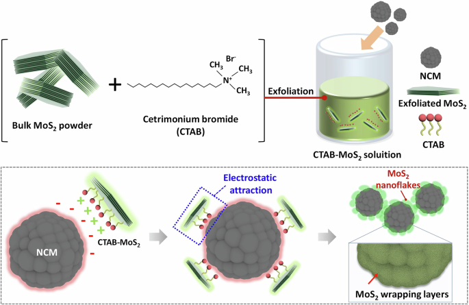
Schematic illustration of a MoS2-wrapped cathode preparation procedure. The surface of NCM is wrapped by surface-functionalized MoS2 nanosheets.
Results
Conformal MoS2 wrapping on Ni-rich cathode materials
To achieve effective and complete self-assembly, overcoming the repulsive force between the negatively charged NCM (Li0.98Ni0.83Mn0.05Co0.11O2) cathode (Supplementary Table S1) and MoS2 nanosheets was required. To this end, we introduced a CTAB surfactant to modify the surface charge of MoS2, resulting in a positive inherent charge. This modification facilitates electrostatic attraction between the two materials, as illustrated in Fig. 1. The negative surface charge of the NCM particles was successfully counteracted by the attachment of the positively functionalized MoS2 (f-MoS2) nanosheets. In this approach, CTAB was chosen as the surfactant because of its capability to induce a positive surface charge on MoS2 while maintaining the high dispersion stability of the nanosheets in an aqueous solution. To compare the impact of surfactant presence on the exfoliation and optical properties of f-MoS₂, the UV–vis spectra of MoS₂ dispersions with and without CTAB were analyzed. MoS₂ and f-MoS2 exhibit similar peak positions in their UV–vis spectra, but the shape of the spectra shows noticeable differences (Supplementary Fig. 1). According to previous studies, such variations can be attributed to changes in the thickness and lateral size of the exfoliated flakes34. The UV–vis spectra of MoS₂ exfoliated without CTAB indicate the presence of thicker and larger flakes. This observation aligns with the lower exfoliation efficiency in the absence of surfactants, which reduces the yield of thinner flakes and leads to a dominance of thicker nanosheets in the dispersion. It highlights the role of surfactants in achieving efficient exfoliation and controlling nanosheet properties. The UV–vis spectrum of the f-MoS2 dispersion exhibited clear excitonic peaks, indicating that the intrinsic properties of MoS2 were retained even after the incorporation of CTAB (Fig. 2a). Zeta potential measurements revealed that as-exfoliated MoS2 nanosheets had a peak value of -20.1 mV, which is attributed to unintentional electron doping caused by sulfur vacancies during exfoliation (Fig. 2b). In contrast, f-MoS2 exhibits a positive zeta potential value of 42.3 mV due to the presence of the cationic surfactant CTAB. With the modulation of surface properties, a simple mixing process allowed the spontaneous wrapping of the NCM cathode surface with f-MoS2 nanosheets through hydrogen bonding and/or electrostatic interactions, enabling a facile assembly route for 2D-wrapped NCM. Unlike previous approaches using reduced graphene oxide (rGO) or CVD-grown graphene that required harsh conditions such as high process temperatures ( > 300 °C) or severe pH range using H2SO435,36,37,38,39, our method offered a simpler and more effective strategy under moderate process conditions. This method does not cause significant damage or contamination to the cathode materials. Raman spectroscopy confirmed the presence of f-MoS2 on the wrapped NCM surface (Fig. 2c). Two peaks at 377.8 cm−1 and 402.9 cm−1 are the representative E12g and A1g Raman modes of MoS2, respectively. Powder X-ray diffraction (XRD) measurements were performed to examine the crystalline structures of NCM and MoS2@NCM (Fig. 2d). Both NCM and MoS2@NCM exhibited a layered structure with an R3m space group without any notable impurities. The intensity ratio of the (003) and (104) peaks (I003/I104) indicated the degree of cation mixing and structural ordering, exhibiting similar values for NCM (1.13) and MoS2@NCM (1.33). The peak splitting of the (110)/(108) and (006)/(102) planes also implies a well-ordered layered structure. This indicates that the original structure was maintained without obvious diffraction pattern shifts or modifications despite the surface modification using f-MoS2 nanosheets. The absence of MoS2 signals in the XRD pattern is attributed to the ultrathin wrapping of a small amount of MoS2 nanosheets on the NCM surface. However, the X-ray photoelectron spectroscopy (XPS) analysis clearly validated the presence and chemical composition of the MoS2 wrapping layer (Supplementary Fig. 2). The thermal decomposition of NCM and MoS2@NCM was investigated using thermogravimetry-derivative thermogravimetry (TGA-DTG) (Supplementary Fig. 3). The DTG curve is the first derivative of the thermogravimetry (TG) curve, and provides information on sample mass loss. A weight loss at a low-temperature range (30–200 °C) is due to the desorption of physically absorbed moisture (LiOH·H2O)40,41. While additional weight loss was not observed for NCM, multiple decomposition steps were confirmed for MoS2@NCM in the range of 250–600 °C, which are related to the decomposition of CTAB and MoS2 species. A slightly lower weight loss was observed for MoS₂@NCM compared to pristine NCM. This suggests that the MoS₂ wrapping layer may enhance thermal stability by reducing oxygen release and suppressing secondary reactions, such as the formation of lithium carbonate. Additionally, the MoS₂ wrapping layer is expected to act as a protective layer, minimizing the exposure of the cathode surface to reactive environmental conditions and mitigating the release of lattice oxygen during thermal decomposition.
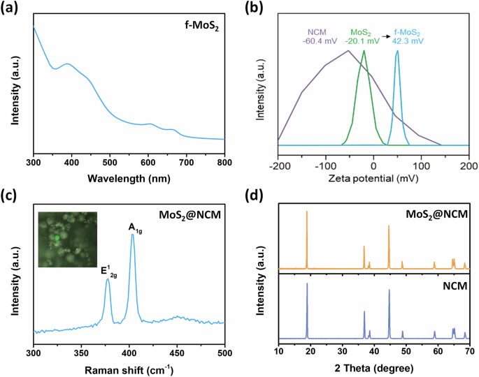
a UV-vis spectra of surface-functionalized MoS2 dispersion. b Zeta potential of MoS2 nanosheets before and after surface functionalization. c Raman spectra of f-MoS2-wrapped NCM particle. Inset exhibits optical image of NCM. d XRD patterns of NCM cathode after (orange) and before (blue) wrapping with surface-functionalized MoS2.
To examine the surface morphologies and the presence of MoS2 wrapping layers, we conducted microscopic analyses, including scanning electron microscopy (SEM) and transmission electron microscopy (TEM) (Fig. 3). The NCM cathodes consisted of secondary particles with densely packed small primary NCM crystallites (Fig. 3a, b). A TEM image of pristine NCM without surface modification, shown in Fig. 3c, reveals a lattice distance of 0.47 nm corresponding to the (003) plane in the layered NCM cathode (Fig. 3d). In contrast, MoS2@NCM exhibited smoother surface features without structural degradation because the protruding NCM particles were covered with f-MoS2 wrapping layers (Fig. 3e, f). The ultrathin f-MoS2 wrapping layers were homogeneously and clearly coated along the surface of the NCM particles with a thickness of approximately 2 nm without noticeable cracks or fractures (Fig. 3g). The uniform and ultrathin nature of the f-MoS2 wrapping layer on the NCM cathode enabled the maintenance of the layered structure of MoS2@NCM. The wrapping layer provides a conformal coating that is expected to enhance structural stability by mitigating mechanical stresses within the cathode particles. During the charging and discharging process, Ni-rich layered cathodes are known to undergo volume changes due to repeated lithiation and delithiation, which can lead to internal microcrack formation. It demonstrates the potential of the MoS2 wrapping layer to mitigate these issues14. To investigate the atomic distribution in MoS2@NCM, we performed scanning transmission electron microscopy-energy dispersive x-ray spectroscopy (STEM-EDS) elemental mapping (Fig. 3h), which revealed a uniform distribution of Mo and S throughout the NCM, indicating the formation of a MoS2 wrapping layer on the NCM particle surface.
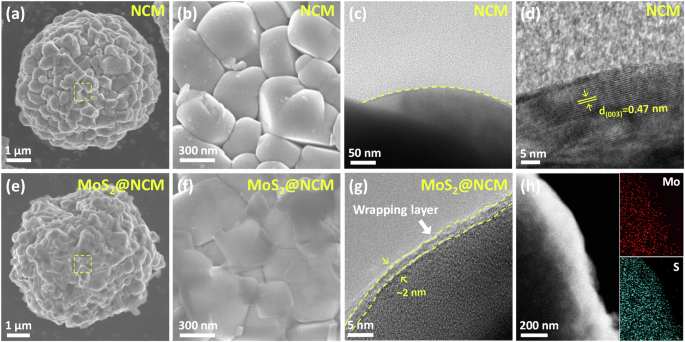
a, b SEM images of pristine NCM. c, d TEM images of pristine NCM. e, f SEM images of MoS2@NCM. g TEM images of MoS2@NCM. h Elemental mapping images of molybdenum, and sulfur in MoS2@NCM.
Improved electrochemical performance of MoS2-wrapped Ni-rich cathode
The electrochemical performances of pristine NCM and MoS2@NCM were evaluated to reveal the protective effect of the wrapping layer against cathode degradation (Fig. 4). The 1st and 50th charge/discharge profiles are shown in Fig. 4a. The 1st discharge capacity of pristine NCM was 185.8 mAh g−1, whereas the MoS2@NCM cathode exhibited a higher discharge capacity of 195.5 mAh g−1. The initial capacity loss in pristine NCM is attributed to irreversible structural transitions in the cathodes and the formation of surface impurities due to loss of active Li+ ions. The MoS2 wrapping layers on NCM cathodes play a crucial role in preventing undesirable surface degradation and interfacial side reaction during initial cycling. Supplementary Fig. S4 shows the capacity retention of pristine NCM and MoS2@NCM in the voltage range of 2.5–4.3 V at 0.1 C. After 50 cycles, the discharge capacity of pristine NCM declined to 151.8 mAh g−1, reaching a capacity retention of 81.7% compared to the first cycle. This can be attributed to the unwanted surface reactions caused by the high Ni content. However, the MoS2@NCM cathode exhibited a discharge capacity value of 167.2 mAh g−1 after 50 cycles, which indicated a lower capacity degradation (capacity retention of 85.5%) than pristine NCM. Figure 4b shows the long-term cycle performance of pristine NCM and MoS2@NCM. After 100 cycles, pristine NCM only maintained 128.0 mAh g−1 with a capacity retention of 68.9%. This capacity fading is largely attributed to the phase transition that causes cation mixing and irreversible oxygen loss, resulting in phase degradation of the surface into rock-salt structures. In addition, the occurrence of side reactions at the interface between NCM cathode materials and electrolytes and dissolution of the transition metal are also factors for capacity degradation. These are triggered by the products of electrolyte decomposition, such as HF from the reaction of PF5 with H2O16,42. In contrast, MoS2@NCM maintained a higher discharge capacity of 141.9 mAh g−1 after 100 cycles with a capacity retention of 72.6%. This enhanced stability can be ascribed to the presence of MoS2 wrapping layers, which prevent the undesirable surface degradation of the cathode. In addition, the MoS2 nanosheets, characterized by their small lateral size ( < 500 nm), did not hinder Li ion transport during charging/discharging, even after attachment to the NCM surface. The rate capability test was evaluated at high current densities of 0.5 C and 1.0 C (Supplementary Fig. 5). While MoS2@NCM exhibited a significant higher capacity retention and retained a higher discharge capacity than pristine NCM during cycling. These results also demonstrate that the MoS2 wrapping layers not only mitigated the degradation of NCM but also enabled rapid charge/discharge.
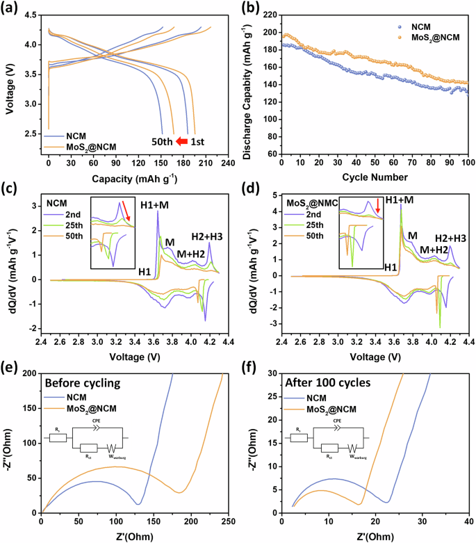
a Initial and 50th charge/discharge voltage curves of NCM and MoS2@NCM. b Cycle performance of NCM and MoS2@NCM. dQ/dV vs. voltage curves of (c) NCM and (d) MoS2@NCM. EIS spectra of NCM and MoS2@NCM for (e) before cycling and (f) after 100 cycles.
To evaluate the electrochemical mechanism and phase transition during charging/discharging, the differential capacity (dQ/dV) curves were obtained for different cycles (Fig. 4c, d). The four kinds of noticeable redox peaks are related to multiple phase transitions in the lithiation and delithiation of cathode materials43. The main redox peaks can be assigned to the phase transition from the hexagonal layered structure (H1) to a monoclinic phase (M), from M to the second hexagonal phase (H2), and then from H2 to the third hexagonal phase (H3)44. Irreversible phase transition of H2 + H3 in nickel-rich cathodes leads to severe polarization and causes an abrupt volume contraction of the unit cells along the c-axis and bulk structural collapse45,46. The H2 + H3 peak in the 2nd cycle curve of the NCM gradually decreased in intensity in subsequent cycles and shifted to a high voltage (Fig. 4c), indicating the increased polarization and severe capacity fading during cycling. In contrast, the H2 + H3 phase transition of MoS2@NCM was effectively suppressed, with a lower polarization after the introduction of the MoS2 wrapping layer (Fig. 4d). The dQ/dV curves of MoS2@NCM were successfully maintained during cycling, suggesting that improved structural stability and reversible transitions were achieved using an ultrathin MoS2 wrapping layer for surface protection.
Electrochemical impedance spectroscopy (EIS) analysis was performed to assess the charge transfer resistance of the cells by comparing pristine NCM with MoS2@NCM. The EIS results before and after the 100th cycle are shown in Fig. 4e, f. The charge transfer resistance of NCM and MoS₂@NCM was investigated using equivalent circuits based on the Nyquist plots before cycling and after the 100th cycle. The semicircle at high frequencies is mostly related to resistive effects owing to the presence of surface films and the formation of a double layer, and to the charge transfer process at electrolyte-electrode. The straight line at low frequencies is the Warburg impedance related to the diffusion of Li ions47,48,49. Before cycling, the charge transfer resistances of NCM and MoS2@NCM were 127.6 and 170.8 Ω, respectively. The MoS2@NCM exhibited a higher charge resistance than NCM because the charge transfer reaction was slightly impeded by the MoS2 wrapping layers on the cathode particles during the initial cycles (Fig. 4e). However, after 100 cycles, the semicircle of NCM@MoS2 (13.1 Ω) in the high-frequency region became smaller than that of NCM (18.6 Ω). This suggests that the MoS2 wrapping layer effectively suppressed the surface degradation of the layered NCM structure and consequently mitigated the increase in charge transfer resistance during cycling (Fig. 4f). Compared to previous studies utilizing surface coatings on Ni-rich NCM cathodes, MoS₂@NCM demonstrates enhanced battery performance, with significant improvements in cycling stability. This highlights the effectiveness of the MoS₂ wrapping layer in mitigating surface degradation, suppressing oxygen release, and maintaining structural stability during long-term cycling.
Mitigation of intergranular cracking in MoS2-wrapped Ni-rich cathode
To investigate the structural stability and degradation mechanism of NCM and MoS2@NCM, cross-sectional observations of the cycled electrodes were performed using focused ion beam scanning electron microscopy (FIB-SEM) (Fig. 5). Figure 5a, b shows the cross-sectional SEM images of the NCM and MoS2@NCM electrodes before cycling, respectively. Both NCM and MoS2@NCM exhibited dense secondary particles and well-structured features without visible microcracks. After 20 cycles at a high current density, intergranular cracking was observed in pristine NCM owing to a repeated irregular structural stress and unit cell volume changes (Fig. 5c)50,51,52. These microcracks, which are caused by interfacial mechanical stress, contribute to capacity fading and structural degradation53,54. Furthermore, the electrolyte can permeate into the secondary particles through the cracks, resulting in electrolyte decomposition, phase transition, oxygen evolution, and transition metal dissolution55,56,57,58. In contrast, MoS2@NCM exhibited negligible intergranular cracking compared to pristine NCM, indicating that the original structure did not notably change even after 20 cycles (Fig. 5d). These observations demonstrate the efficacy of the MoS2 wrapping layer in enhancing the electrochemical performance by ensuring structural stability.
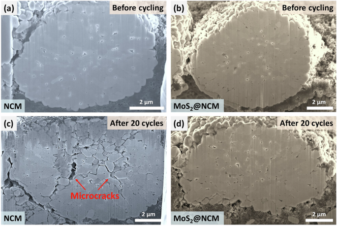
Cross-sectional SEM images of before cycling (a) NCM and (b) MoS2@NCM and after 20 cycles (c) NCM and (d) MoS2@NCM.
Surface and chemical stability of MoS2-wrapped Ni-rich cathodes
To further investigate the surface features and chemical structures after cycling, ex-situ XPS analyses of the NCM and MoS2@NCM cathodes were performed before and after 50 cycles (Fig. 6). Figure 6a–d shows the C 1 s, O 2 s, F 1 s, and Ni 2p spectra of NCM and MoS2@NCM cathodes before cycling. In the C 1 s spectrum, C C-C, C-H, C-O, C = O, and CF2 peaks were observed in both the NCM and MoS2@NCM samples (Fig. 6a). The C-C peak is associated with conductive carbon, and the C-H and CF2 peaks originate from polyvinylidene difluoride (PVDF). The peaks at 529.5, 531.6, and 533.1 eV in the O 1 s spectra are assigned to the lattice oxygen (M-O), impurity oxygen (Li2CO3/LiOH), and C-O, respectively (Fig. 6b)59,60. For F 1 s spectra, the peaks at 684.9 and 687.8 eV are attributed to LiF and C-F (PVDF), respectively (Fig. 6c). LiF can be generated by dehydrofluorination of the PVDF during the process of preparing the electrode slurry61. In the Ni 2p spectra, peaks observed at 854.3 and 856.60 eV correspond to Ni2+ and Ni3+, respectively, and satellite peaks are also observed around 861.6 eV owing to shake-up processes (Fig. 6d)62. The peaks in the spectra of NCM and MoS2@NCM samples are similar. Figure 6e–h show the C 1 s, O 1 s, F 1 s, and Ni 2p spectra of the NCM and MoS2@NCM cathodes after 50 cycles. In C 1 s, the C = O and C-O peaks of NCM were significantly higher than those of MoS2@NCM because of the formation of Li2CO3 impurities and organic products (R-OCO2-Li, and R-COOLi) as a result of side reactions with the electrolyte (Fig. 6e). The side products could be derived from carbonate and organic groups caused by electrolyte oxidation63. For O 1 s, the peak intensity of C-O and CO3/O-C = O species increased for the cycled NCM sample, corresponding to R-COOLi, R-OLi, or Li2CO3 species originating from the decomposition of the carbonate solvent (Fig. 6f)64. On the other hand, cycled MoS2@NCM exhibited smaller peaks for C-O and CO3/O-C = O species than the cycled NCM, which implies that the MoS2 wrapping layer effectively decreased the oxidation of electrolyte/surface Li residues and enhanced the surface stability. The formation of LixPOyFz and LiF was observed in the F 1 s spectra of both samples and is related to the decomposition of the LiPF6 salt and electrolyte degradation (Fig. 6g). However, the peak ratio between the [LixPOyFz+LiF] and [C-F] for the cycled MoS2@NCM electrodes was smaller than that of the cycled NCM. The Ni 2p3/2 peak is deconvoluted into Ni2+ (855.6 eV) and Ni3+ (856.6 eV) peaks (Fig. 6h). The high proportion of Ni2+ not only caused severe cation mixing, but also resulted in the formation of a rock-salt phase on the surface. Furthermore, the presence of NiO (858.5 eV) implied that the rock salt phase grew during cycling. The Ni2+/Ni3+ ratio was determined by calculating the peak areas. The Ni2+/Ni3+ peak ratios of NCM and MoS2@NCM are 0.69, and 0.25, respectively. In this regard, the amount of Ni2+ in MoS2@NCM was lower than that in NCM, confirming that relatively fewer Ni2+ species existed on the surface of MoS2@NCM because of reduced cation mixing between Li+ and Ni2+. These spectroscopic results demonstrate that the MoS2 wrapping layers play a significant role in reducing the surface-induced structural degradation of NCM, as well as decreasing side reactions with the electrolyte, gas evolution, and polarization during cycling.
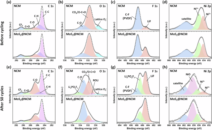
Ex-situ XPS spectra of NCM and MoS2@NCM before cycling (a) C 1 s, (b) O 1 s, (c) F 1 s, (d) Ni 2p and after cycling (e) C 1 s, (f) O 1 s, (g) F 1 s, (h) Ni 2p.
Mitigation of electrolyte decomposition and gas evolution in MoS2-wrapped Ni-rich cathodes
In-situ DEMS analysis was performed to investigate the gases generated from the NCM and MoS2@NCM cathodes during the initial charging/discharging (Fig. 7a, b). The oxidative decomposition of the electrolyte and the severe side reaction between the lattice oxygen that is released from the Ni-rich layered cathode and the electrolyte at high charge states can lead to gas generation65,66. This gas generation is caused by the overlapping area of the Ni3+/4+ eg band, with the top of the O2- 2p band being smaller than that of the Co3+/4+ t2g band67,68. Thus, during the delithiation process in the Ni-rich cathode, electron delocalization, which provides a high capacity, is observed with Ni3+/4+. However, the increased Ni content not only oxidizes the lattice oxygen but also weakens the oxygen binding strength through the oxidation of Ni3+. This weakening of the oxygen binding strength inevitably leads to the release of oxygen69. The gas evolution from the Ni-rich layered cathodes fatally influences safety issues, electrode degradation, cycle life, and cell impedance. Surface impurities involving parasitic reactions and gas evolution from highly Ni-rich layered cathodes also lead to unwanted cell degradation70. Therefore, we investigated whether the MoS2 wrapping layer can stabilize the electrode surface by preventing the formation of residual lithium and reducing gas evolution. The cells with NCM and MoS2@NCM cathodes were charged to 4.5 V, and the CO2 and O2 emissions from the cathode materials were identified and quantified. During the first charging process, the degree of O2 generation in the NCM and MoS2@NCM cathodes exhibited negligible differences. However, there was a noticeable difference in CO2 generation between NCM and MoS2@NCM. It is known that the generation of CO2 occurs by the decomposition of organic solvents and the direct electrochemical oxidation of carbonate molecules63,71,72,73,74. Compared with NCM, a small amount of CO2 was generated during charging in MoS2@NCM (Fig. 7a, b). The reduced gas evolution behavior of MoS2@NCM indicates that the MoS2 wrapping layers successfully stabilized the surface of the NCM cathode and reduced undesired interfacial side reactions between the electrode and electrolyte during high-voltage charge/discharge cycling, improving safety and electrochemical performance.
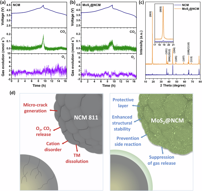
In-situ DEMS and voltage profile during 1st charging for (a) NCM and (b) MoS2@NCM. (c) Ex-situ XRD patterns of NCM and MoS2@NCM after 50 cycles. (d) Schematic illustration of functional effects of MoS2@NCM cathode.
To investigate the structural changes and electrochemical mechanism during cycling, ex-situ characterization of the NCM and MoS2@NCM electrodes was performed after 50 cycles. In the ex-situ XRD results for the pristine NCM and MoS2@NCM electrodes (Fig. 7c), NCM and MoS2@NCM maintain their original structures with no peak appearance or shift after 50 cycles. The 50-cycled NCM shows a low intensity (003) peak, whereas the (003) peak for the 50-cycled MoS2@NCM exhibits a relatively sharp and high intensity. It is worth noting the (003) and (104) peak intensity ratios42. It is generally known that the peak intensity ratio of I003/I004 indicates the degree of cation mixing and structural ordering in layered cathode materials. A peak intensity ratio less than 1.2 indicates a significant amount of cation mixing, whereas a peak ratio higher than 1.2 indicates a well-ordered structure or negligible cation mixing. The I003/I004 value of pristine NCM was 0.13, whereas the I003/I004 value of MoS2@NCM was 2.38, indicating that the layered structure of MoS2@NCM was stable even after 50 cycles. The peak splitting of the (110)/(108) and (006)/(102) planes also indicates a well-layered hexagonal structure. It is conceivable that the MoS2 layers wrapping the NCM cathodes effectively suppressed Li+/Ni2+ cation mixing and stabilized the electrode surface, thereby maintaining the original layered NCM structure during repeated charging/discharging. Figure 7d shows a schematic illustration of the functional effects of the MoS2 wrapping layers, which enhance the structural stability and electrochemical properties of the Ni-rich layered cathodes. The improved electrochemical properties of MoS2@NCM as a cathode material can be attributed to the following reasons. (i) The formation of thin and uniform MoS2 wrapping layers enhanced the structural stability by acting as a protective layer without negatively affecting the cathode material. (ii) Owing to the MoS2 layers, irreversible phase transition and TM dissolution were suppressed during cycling. (iii) The MoS2 layers effectively suppressed gas evolution (O2 and CO2) during charging ( > 4.5 V) by reducing the direct contact between the electrolyte and the cathode surface.
Discussion
In summary, we successfully demonstrated a simple and effective surface-wrapping method using 2D MoS2 nanosheets. The application of this method enhances the long-term stability and operational safety of Ni-rich layered cathode particles in advanced electrode designs for LIBs. By employing positively functionalized MoS2 nanosheets, we achieved conformal coverage of negatively charged NCM cathode surfaces via self-assembly. The ultrathin and uniform MoS2 wrapping layer provides multiple benefits. These include the mitigation of surface-induced structural degradation of the NCM cathode during cycling, improved interfacial kinetic properties, enhanced cell stability, and protection against mechanical failure-induced microcrack formation and subsequent electrolyte penetration inside the cathode. In addition, the MoS2 wrapping layer effectively mitigates gas evolution, thus contributing to enhanced structural stability. Furthermore, the introduction of the MoS2 wrapping layer reduces undesired interfacial side reactions between the electrode and electrolyte. This results in a reduction in the accumulation of side products, such as Li2CO3 impurities and organic compounds originating from electrolyte decomposition at high voltages, on the cathode surface. These findings not only highlight the potential of this effective wrapping strategy for various electrode materials, but also offer opportunities for their application in other areas requiring ultrathin and compact surface protection.
Methods
Dispersion preparation of positively charged MoS2 nanosheets
To perform liquid phase exfoliation, we utilized 0.2 g of MoS2 powder (purchased from Sigma-Aldrich), which was exfoliated in a 45 ml aqueous solution of 10 wt% CTAB (purchased from Sigma-Aldrich). The exfoliation process was carried out using a tip sonicator at 40 W for 2 h in an ice bath to maintain a low temperature. Subsequently, the resulting MoS2 dispersion was centrifuged at 5000 rpm for 10 min to remove any unexfoliated bulk powder.
Fabrication of the MoS2 wrapped NCM cathode
The MoS2@NCM cathode was prepared through a wet chemical coating process. The active material, Li0.98Ni0.83Co0.11Mn0.05O2 (obtained from MSE Supplies LLC), was mixed with a 10 wt% CTAB-MoS2 solution and stirred at room temperature for 1 h. Subsequently, the mixture was freeze-dried for 72 h to form the MoS2@NCM powder.
Material characterization
The crystalline phases of the sample were characterized using XRD (D8 Advance, Bruker) with Cu-Kα (λ = 1.54 Å) radiation. Surface morphologies and microstructures were characterized using SEM (JSM-7600F, JEOL). The crystalline structure and elemental distribution were analyzed by TEM (JEM-2100Plus, JEOL), and the elemental compositions were determined by EDS. After cycling, the cross-sectional images of the samples were obtained using FIB-SEM (Helios G4, Thermo Fischer Scientific). The surface atomic chemical compositions were analyzed using XPS (K-alpha, Thermo U.K.). Inductively coupled plasma- optical emission spectrometry (ICP-OES, 5110, Agilent) was conducted to quantify the Li, Ni, Co, and Mn contents of the active material. TGA (TGA4000, SINCO) was used to analyze the thermal decomposition of the samples. The UV-visible spectra were obtained by measuring MoS2 dispersion in quartz cuvettes (Agilent Technologies Cary 5000). The Raman spectra were acquired using a 532 nm laser source (Alpho300R spectrometer). Zeta potential measurements of the MoS2 and NCM were conducted using a Zetasizer analyzer (Malvern Instruments).
Electrochemical characterization
A slurry consisting of 85 wt% active material, 8 wt% conductive material (Super-P), and 7 wt% PVDF was prepared. The electrodes were prepared by coating the slurry onto an Al foil using a doctor blade with a thickness of 200 mm. After coating, the electrodes were dried in a vacuum oven at 110 °C for 12 h prior to cell assembly. The thickness and loading mass of the MoS2@NCM electrode are approximately 53 μm and 11.4 mg cm⁻², respectively. The half cells were assembled in an Ar-filled glove box (MBraun, Korea) with O2 and H2O concentrations below 0.1 ppm, using punched electrodes (14 mm in diameter) as the working electrodes. A Li metal foil served as the counter electrode. The electrolyte consisted of 1 M LiPF6 in a mixture of ethylene carbonate and diethyl carbonate (1:1 v/v) with 5 wt% fluoroethylene carbonate. Celgard 2500 polypropylene (19 mm diameter) was used as the separator. Electrochemical performance measurements were conducted using a potentio-galvanostat (WBCS3000, WonATech, Korea) at a constant current density of 25 mA g−1 within the voltage range of 2.5–4.3 V vs Li/Li+. EIS was conducted using a Bio-Logic VSP potentiostat, measuring frequencies from 100 kHz to 0.01 Hz with an amplitude of 5.0 mV.
Ex-situ Characterization
Cross-sectional images of the electrodes were acquired using FIB-SEM after 20 cycles. The electrodes were prepared after galvanostatic charge and discharge in the voltage range of 2.5–4.3 V at a current density of 125 mA g−1. The structural changes and surface characteristics of the electrodes were assessed using XRD and XPS. The electrodes were prepared after galvanostatic charge and discharge in the voltage range of 2.5–4.3 V at a current density of 25 mA g−1.
In-situ DEMS
In-situ DEMS analysis was conducted to measure the amount of O2 and CO2 gases generated during the first charge/discharge cycle. The DEMS cells (CA-4-IWOS, Wellcos Co.) were assembled in an Ar-filled glove box. To detect gas evolution from the coin cell system, a perforated plate was positioned on the top side of the cell, and a glass fiber membrane was used as the separator. The coin cells were sealed using the top and bottom SUS plates with leak-free Si rings. The DEMS analysis line consisted of an Ar carrier gas, flow controller, mass spectrometer, and inlet/outlet gas line for the cell connection. To minimize undesired components from the tube lines, the lines were evacuated for 30 min, and the cell was purged with Ar. Following the connection of the cells and lines, high-purity Ar (99.999%) was used as the carrier gas, flowing at a rate of 10 cm3 min−1. The cells underwent charging and discharging at a current density of 25 mA g−1 within the voltage range of 2.5–4.5 V vs Li/Li+. Data acquisition and calibration parameters of the mass spectrometer were performed using the QGA professional software (Hidden Analytical, UK).
Responses