CFD comparison of novel [emim][DCA] and [emim][MS] ionic liquids for the separation of CO2 greenhouse gas in the membrane contactor
![CFD comparison of novel [emim][DCA] and [emim][MS] ionic liquids for the separation of CO2 greenhouse gas in the membrane contactor](https://i2.wp.com/media.springernature.com/lw685/springer-static/image/art%3A10.1038%2Fs41598-025-90289-5/MediaObjects/41598_2025_90289_Fig1_HTML.png?w=1024&resize=1024,1024&ssl=1 "CFD comparison of novel [emim][DCA] and [emim][MS] ionic liquids for the separation of CO2 greenhouse gas in the membrane contactor")
Introduction
Substantial growth toward the industrialization process of modern countries has resulted in the abnormal release of detrimental greenhouse compounds as like as CO2 to the environment1,2,3,4. CO2 has recently been introduced as the prominent cause of global warming. It reported by the researchers that the emitted amount of CO2 increased considerably from 200 ppm in 1840 to about 425 ppm in 20245,6. In doing so, developing more efficacious CO2 separation techniques is a momentous challenge to mitigate its emission into the atmosphere.
In the current years, the utilization of HFMCs as a relatively new membrane-based process has gained indisputable interest compared to other commonly-employed techniques of CO2 capture7. The emergence of brilliant advantages like modularity, simple scale-up, high interfacial area and negligible unloading at low flow rates has made the application of HFMCs promising in the membrane-based CO2 separation technology. However, some drawbacks like high capital/operating cost, low chemical resistance and fragility during operation must be considered as the main challenges of industrial application of HFMCs8,9,10. In 1985, the employment of HFMC was first studied by Qi and Cussler for the absorption of CO2. They found this reality that the HFMC could provide higher area per volume compared to commonly-applied packed towers, which significantly enhanced the separation performance11. Then after, different researchers have used this novel gas-liquid contact technology for the sequestration of CO2. For instance, Bagi et al. mathematically evaluated the removal yield of CO2 inside the contactor utilizing piperazine as chemical absorbent. They concluded that the use of piperazine with concentration, liquid and gas flow rates of 1080 mol m− 1, 400 mL min− 1 and 180 mL min− 1 demonstrated an incredible separation performance (95%)12. In another investigation, Bozonc et al. employed HFMC for enhancing the removal of CO2 using monoethanolamine (MEA) solution. They perceived that the inner radius’ increment of membrane from 0.01 to 0.5 mm significantly improved the removal performance from 58 to about 99%13.
Disparate chemical absorbents such as alkanolamine solutions, amino acid absorbents and alkali solutions have illustrated different efficiencies in HFMCs for CO2 capture. Despite suitable efficiency, the emergence of some operational and environmental challenges including eco-toxicity, corrosion and high vaporization losses has significantly restricted their wide applications for CO2 capture14,15,16. Ionic liquids (ILs) belong to a novel category of chemical absorbents made of ions instead of molecules. Indisputable advantages of ILs such as low volatility, negligible vapor pressure, low clogging in the membrane pores, good stability in different temperature, inflammability and eco-friendliness has made them promising for CO2 capture through HFMCs17,18,19. In an investigation, Sumayli et al. compared the removal performance of [bmim][PF6], [bmim][BF4] and [emim][etSO4] ILs with pure H2O through HFMC. Based on their evaluation, [bmim][BF4] was considered as the best IL for removing CO2 (100% [bmim][BF4] vs. 99% [bmim][PF6] vs. 97.5% [emim][etSO4] vs. 55% H2O)14.
In the recent decades, application of CFD as a versatile and powerful tool to solve complex technical/physical problems in disparate industrial approaches such as membrane separation, drug delivery, reactor design and wastewater treatment20,21,22,23,24. The emergence of important advantages like acceptable accuracy, cost-saving nature, and suitable visualization has convinced the scientists to involve CFD technique for the analysis of results of CO2 capture through HFMCs25. As an example, Sayyah Alborzi et al. computationally studied the absorption performance of CO2 greenhouse contaminant inside the membrane contactor using a mixed solution of dimethylaminoethanol and 3-methylaminopropylamine. They perceived that 5% wettability of membrane micropores significantly deteriorated the CO2 sequestration efficiency through the contactor owing to increasing the mass transfer resistance26. In another research, Mousavian et al. numerically simulated a HFMC for the absorption of CO2 applying MEA amine absorbent. They found that the increase of liquid flow rate from 3 to 11 L h− 1 improved the separation of CO2 from 71 to 84%27.
In this paper, the authors have made their effort to develop a mathematical model following to a 2D CFD simulation for estimating the sequestration percentage of CO2 pollutant using [emim][MS] and [emim][DCA] ILs in the HFMC. To ensure the precision, model outcomes are compared with obtained experimental data. Additionally, the separation efficiency of CO2 via both ILs are presented and compared with each other to introduce better IL. At the end, the removal percentage of CO2 in wide ranges of different parameters (i.e., porosity, number of fibers, packing density and liquid flow rates) are presented and evaluated comprehensively.
Modeling and simulation
Figure 1 presents the chemical structure of [emim][MS] and [emim][DCA] ILs.
![CFD comparison of novel [emim][DCA] and [emim][MS] ionic liquids for the separation of CO2 greenhouse gas in the membrane contactor](https://media.springernature.com/lw685/springer-static/image/art%3A10.1038%2Fs41598-025-90289-5/MediaObjects/41598_2025_90289_Fig1_HTML.png "CFD comparison of novel [emim][DCA] and [emim][MS] ionic liquids for the separation of CO2 greenhouse gas in the membrane contactor")
Molecular structure of employed ILs [https://www.sigmaaldrich.com/GB/en/product/aldrich/18086; https://solvionic.com/en/ionic-liquids/5746-1-ethyl-3-methylimidazolium-dicyanamide.html].
The prominent aim of this research is the development of an axisymmetrical simulation for the theoretical analysis of CO2 removal from CO2/N2 gaseous flow employing [emim][MS] and [emim][DCA] ILs inside the HFMC. Each Type of HFMC has three main compartments including tube, shell and membrane. CO2 separation process inside the HFMC occurs by the mass transfer of existed CO2 molecules inside the tube to the membrane pores and their absorption via employed ILs in the shell. The molecular mass transfer of CO2 and the associated geometry of a HFMC is presented in Fig. 2.
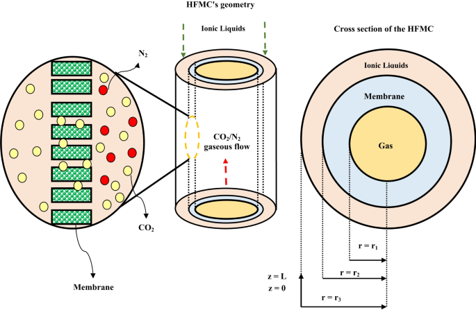
Mass transfer mechanism, geometry and module cross section. Adapted from28.
With the aim of facilitating the process of simulation, the following assumptions must be implemented:
-
1.
Isothermal mode;
-
2.
First-order manner of CO2 molecules.
-
3.
Non-selective essence of employed membrane;
-
4.
Axisymmetrical geometry of module;
-
5.
Non-wetted circumstance of fibers during operation;
-
6.
Employing Henry’s law for the expression of the CO2-ILs equilibrium;
-
7.
Laminar flow regime in the feed gas;
-
8.
counter-current movement of ILs and gaseous flow.
Specifications of module and essential operating conditions for developing the model is enlisted Table 1. In this manuscript COMSOL software version 6 has been employed as a versatile FE-based software for the analysis of PDEs through the prominent compartments of HFMC. To achieve this aim, PARDISO has been selected to solve the governing mass/momentum PDEs inside different sections of contactor owing to possessing brilliant positive points like simple application, high accuracy and ability of solving different boundary problems. It is also important to mention that the needed time for running the geometry and solving the equations is nearly 7 min.
Principal equation for interpreting the mass transport process of CO2 based on aforementioned assumptions through the tube is derived using the following Eqs6,30,31,32:
Based on the assumption of the Newtonian laminar flow regime through the tube, the axial velocity distribution can be rendered by the6,33,34:
Boundary conditions for the tube can be presented using the following equations:
Inside the microporous membrane, the governing equation for analyzing CO2 mass transfer process can be presented by the Eq. 13 ref6,33,35. Due to the consideration of non-wetted mode during the separation process, the micropores of membrane are just filled with gas. In doing so, the prominent mechanism for mass transfer in the membrane pores is only diffusion and is presented by the following Eqs6,18,33.
As can be seen in the Eq. 14, increase in (:{D}_{{CO}_{2},mem}) results in the increment of porosity ((:{upepsilon:})) (direct relationship) and deterioration of membrane tortuosity ((:{uptau:})) (reverse relationship)6,33,36:
Employed boundary conditions inside the membrane is as follows:
To analyze the mass transfer of components i (CO2, [emim][MS] and [emim][DCA]) in the shell, Eq. 19 can be well derived37,38:
Considering two important assumptions in the shell pathway (laminar flow pattern and Happel’s free surface approximation) resulted in the achievement of the velocity profile using Eq.20 ref38:
Additionally, the theoretical effective radius around each hollow fiber is presented by (:{r}_{3}) and derived as follows6:
In this equation, the packing density of fibers ((:(1-phi:))) is anticipated via Eq. 22 ref39,40:
Viscosity of ILs can be regarded as an important parameter, which significantly affects the diffusivity, molecular mass transfer and as the result, separation performance. for the imidazolium-based [emim][MS] and [emim][DCA] ILs, the following equation has been used for the estimation of CO2 diffusion coefficient41:
By the incorporation of Eqs. 21 and 22, the value of r3 is estimated 1.92 × 10− 4 m. Implemented boundary conditions in the shell are as follows:
Physicochemical properties of CO2, [emim][MS] and [emim][DCA] ILs are listed in Table 2.
Results and discussion
Validation
With the aim of insuring the precision of mathematical model, the simulation outcomes for the dimensionless CO2 concentration in the outlet of tube side (Cg, out/Cg, in) are compared with the achieved experimental data from the study of Sohaib et al.29 in an extensive range of N2 flow rate. There has been an acceptable agreement with average deviation of approximately 5%. Figure 3 compares the simulation outcomes for Cg, out/Cg, in with the achieved experimental data.
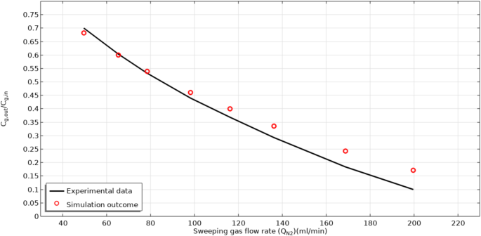
Model validation based on the evaluation of simulation results and experimental data for the.
CCO2,out/CCO2,in in different N2 flow rates. Experimental data was made by Sohaib et al.29. Porosity is fixed at 0.6.
To guarantee the validation of simulation results in both steady and un-steady operational modes, the modeling results were compared with achieved experimental data from the experiment of Sohaib et al.29 in different operational times. As presented in Fig. 4, a favorable accordance was illustrated between simulation outcomes and experimental findings with the average deviation of about 3.5%. These encouraging results imply the validation of developed numerical simulation.
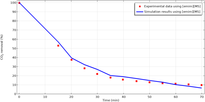
Model validation based on the evaluation of simulation results and experimental data for the CO2 removal percentage in different operational time. Experimental data was made by Sohaib et al.29. Qg=20 ml min− 1.
CO2 concentration profile and removal percentage
Diffusion and convection are known as prominent transport mechanisms in HFMC. Convection occurs in the axial direction (z) owing to the bulk flow of fluids. Also, diffusion transfer mechanism is performed in the radial direction (r) owing to the presence of concentration gradient. The removal process in the contactor occurs by the transfer of CO2 molecules from gas flow (flowing in the shell( to micropores and from micropores to tube and its absorption by the flowing ILs. The concentration distribution through the tube compartment and the dimensionless concentration of CO2 (CCO2,out/CCO2,in) in the tube-membrane interface of contactor are respectively illustrated in Figs. 5 and 6. Owing to the counter-current arrangement of CO2/N2 flow-ILs through the contactor, the CO2/N2 flow moves to the tube from the bottom to top and the flowing ILs move from the top of the HFMC to the bottom. The occurrence of the CO2 mass transfer (because of the concentration difference between both sides of membrane) from the tube to the membrane micropores and from the membrane pores to the shell causes their removal by ILs in the shell segment. By the evaluation of CO2 concentration in tube outlet using Fig. 6, it is perceived that both employed ILs possess excellent separation performance. Evaluation of the figure demonstrates that the employment of both [emim][MS] and [emim][DCA] eventually reduce the dimensionless concentration to zero at the shell outlet (z/L = 1) thank to their instant reaction with CO2 and great removal performance.
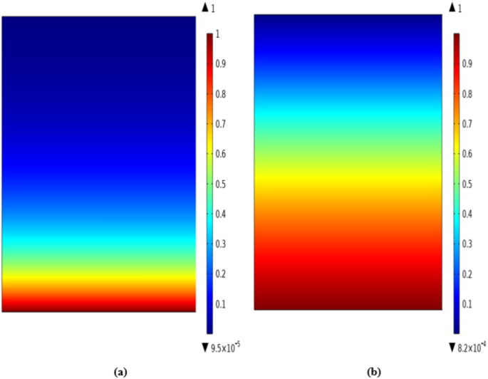
CO2 concentration profile in the tube side using (a) [emim][MS] and (b) [emim][DCA]. The figure has been created using COMSOL Multiphysics software version 6.
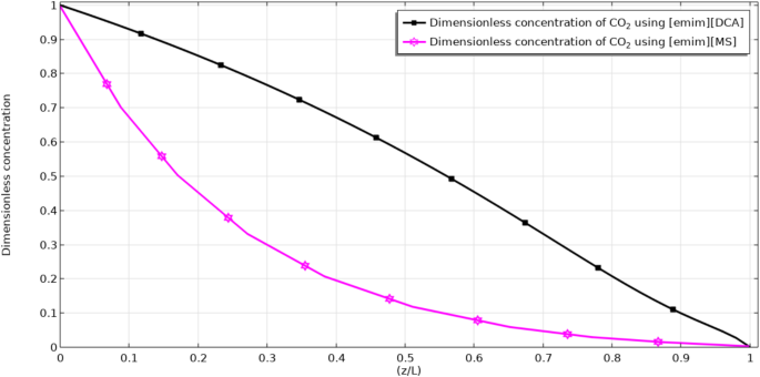
Dimensionless concentration of CO2 in the tube-membrane interface of contactor.
Effect of module/membrane parameters on the separation yield
Equation 27 is usually applied for the prediction of separation through the contactor10,33,48:
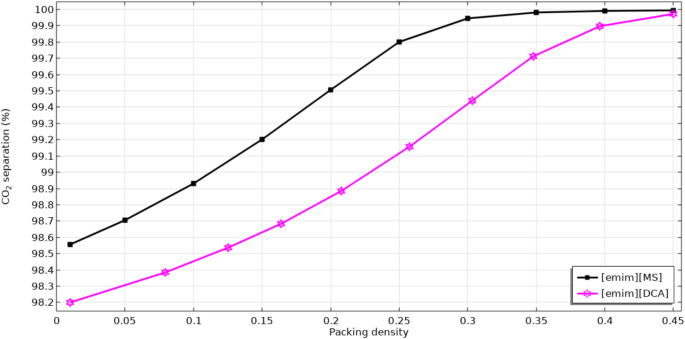
Figure 7 schematically compares the separation percentage of CO2 in an extensive range of packing density using [emim][MS] and [emim][DCA] ILs. Packing density can be described as the ratio between the surface area and the volume of membrane module. As would be expected, enhancement in the packing density factor of microporous membrane significantly increases the mass transfer interface through the module, which causes superior gas-liquid contact and therefor, better separation of CO2.
The role of module length increment on the removal efficacy of CO2.
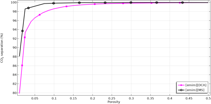
Figure 8 schematically evaluates the operational impact of porosity factor on the sequestration proficiency of CO2. Enhancement in the porosity causes an increment in the effective diffusion coefficient of CO2 through the membrane, which possesses favorable impact on the mass transfer and in doing so, separation rate of CO26,8,49. Significant improvement of CO2 capture performance by enhancing the value of membrane porosity is attributed to this reality that increase in the value of this important parameter improves the opportunity of the CO2 molecular mass transfer inside the micropores and also results in better CO2-ILs reaction Moreover, it is important to note that by the increment of porosity, the resistance against suitable mass transfer significantly declines, which is an encouraging effect toward better removal of CO2 inside the system. Increase in the porosity factor from 0.01 to 0.5 enhances the separation percentage of CO2 from 88 to 100% using [emim][MS] and from 80 to 100% using [emim][DCA].
Impact of porosity on the CO2 separation performance.
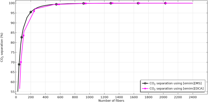
Figure 9 aims to compare the removal performance of CO2 via [emim][MS] and [emim][DCA] in a wide range of hollow fiber numbers. Increase in the fibers’ number results in enhancing the contact area between gas and ILs, which substantially enhances the mass transfer rate and therefore, separation efficiency. As seen, increase in the fibers’ count from 25 to 2400 improves the separation yield from 55 to 100% using [emim][MS] and from 57 to 100% using [emim][DCA].
Effect of hollow fibers’ number on the CO2 separation percentage.
Effect of ILs’ flow rate on the separation of CO2 contaminant through the membrane module is demonstrated in Fig. 10. As expected, increase in the value of liquid flow rate causes an improvement in the turbulency of ILs inside the contactor. It is clear that increase in the turbulency of ILs solutions results in increasing the CO2 mass transfer and therefore, its separation efficiency inside the membrane module. Moreover, increase in the liquid flow rate in the shell of membrane module considerably improves their availability at the liquid boundary layer and thus the absorption efficiency. Based on the figure, improvement in the flow rate of ILs from 20 to 70 lit min− 1 enhances the removal percentage from around 94.75 to 100% for [emim][MS] IL and from 93.9 to 100% using [emim][DCA] IL.
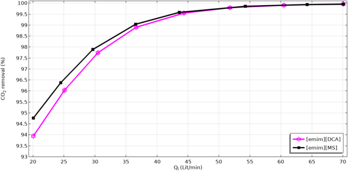
Effect of hollow liquid flow rate on the CO2 separation percentage.
Conclusions
Over the last decades, ILs have been introduced as a breakthrough, cutting-edge, green and efficacious alternative for benchmark alkanolamine solutions. In this research, the authors have made their effort to develop a CFD-based numerical simulation for studying the potential of novel [emim][MS] and [emim][DCA] ILs to separate CO2 greenhouse pollutant inside the HFMC. To solve the governing PDEs of momentum and mass in different compartments of contactor, finite element method was used. Comparison of the simulation results with experimental shows a favorable agreement with average deviation of approximately 5%. Analysis of the model outcomes have corroborated the efficiency of both mentioned ILs for the separation of CO2 with the ability of separating almost all inlet CO2 molecules. It is also recognized from the outcomes that increment in the amount of porosity, hollow fiber numbers and packing density substantially improves the removal efficacy of CO2 owing to enhancing diffusivity, mass transfer area and gas-liquid contact (residence time inside the HFMC.


Responses