Corrosion processes affecting copper-coated used fuel containers for the disposal of spent nuclear fuel: critical review of the state-of-knowledge

Introduction
Nuclear energy has been used as part of global power production for several decades1 and can aid in decreasing carbon emissions by reducing dependence on fossil fuels2. The waste generated, however, presents unique disposal challenges due to its radioactivity and the prolonged time periods over which the waste is hazardous3. The internationally agreed upon solution for spent nuclear fuel (SNF) disposal is the use of deep geological repositories (DGR) to contain and isolate SNF from the environment and biosphere4,5,6.
Many nations globally are pursuing DGRs for safe spent nuclear fuel disposal7,8,9. In general, DGRs rely on a multiple barrier system for the isolation and containment of radioactive material for extended periods of time3. Though designs differ between nations, DGR components usually include a metallic container, a low permeability buffer and a stable geological formation4,10. In Canada, a unique design that is optimized for the waste from the Canadian Deuterium Uranium (CANDU) reactors, and that utilizes available manufacturing capabilities, has been under investigation by Canada’s nuclear waste disposal implementor, the Nuclear Waste Management Organization (NWMO), since 201111. The Canadian design has several distinctive features including the shape of the container (cylindrical shell with hemispherical end caps) and the application of a relatively thin corrosion-resistant copper layer coated on the steel substructure rather than forged as a separate piece11.
Many container materials have been investigated, including carbon steel, stainless steel, titanium, various alloys12 and copper, with reviews published on many aspects of these materials3,12. Copper has been selected as part of several designs due to its thermodynamic stability in the anoxic environments that are expected to characterize the majority of the DGR lifecycle13. However, copper corrosion has been shown to occur in the absence of oxygen if sulfide is present14,15,16,17, requiring the development of a corrosion allowance that estimates the maximum depth of penetration over the lifetime of the DGR. Estimates and corrosion allowances differ between designs and national programs, meaning that a thorough understanding of corrosion processes in relation to the design specifics of the used fuel container (UFC) and DGR is necessary to predict the expected lifetimes of copper containers and ensure that safety requirements are maintained18. Additionally, design and corrosion allowance determinations must be based on, and complemented by, a detailed understanding of the site-specific hydraulic and groundwater characteristics relevant for each repository.
Copper corrosion research in the context of DGRs spans the last several decades; on-going work aims to determine potential corrosion processes and whether the safety and integrity of UFCs can be ensured in different layouts and geological settings3,19. Complete mechanistic understandings of each process involved and how each will impact the integrity of the copper is crucial for ensuring that estimates of container life and corrosion behaviour are accurate, so isolation of the SNF can be ensured18. Though multiple aspects of copper corrosion are well understood (e.g., oxic corrosion, uniform corrosion—corrosion that occurs evenly across the entire surface, or localized corrosion—uneven corrosion with deeper penetration in some areas) and multiple reviews have been published19,20,21, uncertainty still exists for some aspects, particularly with respect to the unique Canadian DGR environment. While extensive research has been conducted to show that the corrosion of the much thinner copper layer used in the Canadian UFC design will not lead to container penetration, reviewed by3,22, the uniqueness of the design merits more detailed research and characterization to confirm that this is the case. With this in mind, a thorough review of the literature was undertaken with the goal of identifying under-studied corrosion mechanisms.
This review examines recent case studies and technical reports from Canada’s NWMO, as well as the broader literature, to determine likely corrosion processes that will affect the copper coating under changing conditions in a DGR. The approach for this review was informed by the guidelines for systematic searches from the Collaboration for Environmental Evidence and included searches in Web of Science, Scopus, the NWMO report database, reference lists from relevant reviews and literature provided by author contacts. See Supplemental Materials 1 for detailed review methodology. Results of the searches and data extraction can be found in Supplemental Materials 2 (descriptive statistics), Supplemental Materials 3 (list of relevant articles included), and Supplemental Materials 4 (list of other articles considered).
This critical review, undertaken to identify knowledge gaps, summarizes the literature and confirms key processes that will impact the corrosion of copper UFCs, with a focus on thermal, hydraulic, chemical, and biological (but not mechanical) conditions that will impact the Canadian design. The combined focus is on both the redox and saturation conditions, and a narrative synthesis and descriptive statistics of the available literature will be presented to provide the evidence for each process discussed. The types of conceptual and mathematical models, as well as the components of these models will be summarized, as will the assumptions and uncertainties associated with both experimental and modeling studies.
Canadian deep geological repository—design and evolution
Corrosion processes of the UFCs in DGRs are controlled by the physical parameters of the container and repository, as shown by ref. 23,24, and the chemistry of the repository environment4. Design specifications of the Canadian reference container and repository have been detailed elsewhere25,26, and reviews of the likely evolution of the repository environment have been completed27. To give context for this review, the relevant design conditions and evolution expectations are briefly described.
Canadian DGR Design
The conceptual DGR depth in the Canadian design (Fig. 1), and most international ones, is approximately 500 m below ground surface or greater9,25,26,28. The Canadian repository and container design was originally based on the KBS-3 repository design that was developed in Sweden and Finland4. The KBS-3 design uses an inner steel vessel for mechanical support and an outer corrosion-resistant copper vessel with a thickness of 50 mm28,29.

Image used with permission from the NWMO.
Starting in 2011, the NWMO undertook research and development efforts to optimize the design for Canadian-used fuel (from the CANDU reactor systems)21,22. The NWMO reference design now uses a smaller container with an inner steel casing and integrally bonded 3 mm copper coating (either electrodeposited or cold-sprayed)25,26 (Fig. 1). Hemispherical heads are used in the Canadian design, rather than flat end caps to reduce the potential tensile stress for the entire container11. The potential for creep of the copper is prevented by integrally bonding the copper to the steel structural support, thereby removing the gap between the two pieces, which is present in the KBS-3 design11. The bodies and end caps of the UFC are fabricated and coated prior to loading of the SNF, and then the steel substrate is welded and cold-spray technology is used to apply copper over the final steel sealing weld, removing the need to apply a weld to the copper11.
In both the KBS-3 design and the Canadian design, highly compacted bentonite (HCB) clay surrounds the copper container3,25,26,28. This layer will both limit microbial growth near the container surface30 and reduce solute transport towards, and away from, the container31. Outside and around the buffer boxes, HCB spacers (which allow some control over the maximum temperature of the emplacement room) and dense backfill materials are used to fill areas between and around emplaced buffer boxes11.
All international designs are ultimately optimized for site-specific characteristics, including the groundwater composition and flow, which differs between nations and sites, even within the same geographic region. In Canada, site selection began in 2010, and two sites with different geological settings remain under consideration32; the crystalline Revell site in northwestern Ontario33 and the sedimentary South Bruce site in southern Ontario34. Site-specific information must be incorporated into the long-term safety assessments that also consider the role of the container and components, as part of the overall repository system35. Generic preliminary safety assessment reports illustrate and evaluate several future evolution scenarios for a hypothetical DGR facility hosted in Canadian crystalline25 and sedimentary26 rock formations.
While multiple repository and container designs have been developed (e.g., the Yucca Mountain project of the United States36, the multilayer steel and concrete supercontainer of the Belgium design37, and the French steel canister design38), the use of different buffer and corrosion barrier materials means that a review of the wealth of information available from these projects is largely outside the scope of the current review, which focuses exclusively on copper container materials.
Evolution of the DGR environment
The physical design parameters are likely to impact corrosion processes by controlling thermal and hydraulic properties of the repository. Over time, the environment of the DGR, including the thermal, hydraulic, chemical, and biological conditions will evolve, leading to a substantial impact on corrosion behaviour. As the DGR ages and moves through its lifecycle, it will move from an oxic period of undersaturation (with respect to water), through a dry, high-temperature period, to a cooler, long-term anoxic period that eventually reaches equilibrium with the chemical characteristics (both redox and ion compositions) of the groundwater in the surrounding bedrock, a process controlled by the geologic environment and the waste behaviour (Fig. 2)27. Based on the saturation, temperature, and oxygen content of the DGR, this review identified six phases in the DGR lifecycle, relevant to a Canadian repository. This is more than the four phases determined by King et al.27 because it includes the pre-emplacement/operational phase and further subdivides the container re-wetting and buffer saturation phases identified previously. Transitions between these phases are marked by identifiable shifts in conditions in the DGR with changes in oxygen concentrations (from oxic to anoxic), temperature (increasing and decreasing with changes in fuel temperature), and saturation (as temperature and groundwater interact with the clay).
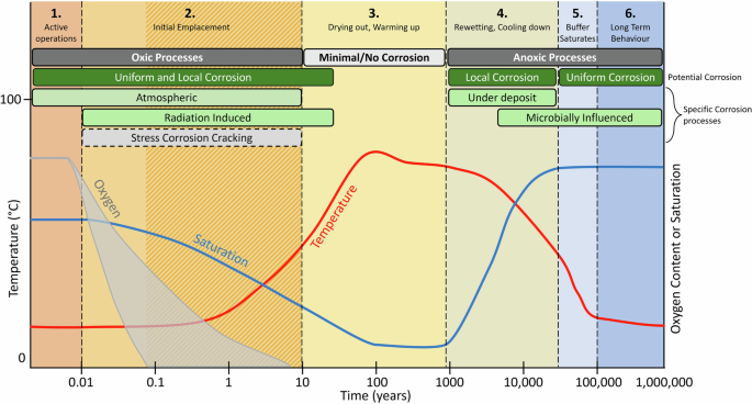
Includes illustrative examples of oxygen, temperature, and saturation variation expected in a DGR environment (temperature variation illustrative of a model crystalline rock, based on the results of Guo94; oxygen concentration variation based on Giroud et al.40, Grandia et al.42, De Windt et al.43 and Yang et al.41 reflecting the uncertainty of the exact time for complete oxygen consumption; saturation variation in the buffer based on King et al.27), and a conceptual model of the evolution of repository environment in a deep geological repository (DGR). Illustration applies to either a crystalline or sedimentary system, however the time to full saturation, and the chemical environment, is likely to be different in each geological setting (e.g., faster re-saturation in fractured, crystalline systems). Adapted from information in King et al.27. Corrosion processes that are likely to occur are marked in green, those that are less likely, but have some potential to occur are marked in light grey, with dashed borders (stress corrosion cracking was the only one of this category identified). The hashed section in Phase 2 indicates that the consumption of oxygen marks the end of the phase, but the exact timing is uncertain.
Oxygen concentrations will drop progressively through the early stages of the repository lifecycle (Fig. 2)39. During active operations, oxygen will be replenished through gas diffusion through the buffer until the UFC and buffer box are loaded into the emplacement room and the room is sealed. Once the emplacement room or repository is sealed, the oxygen concentration will decrease as reactions with the container and other portions of the repository (e.g., pyrite, ferrous inclusions, and microbes in the bentonite or wall rocks) consume the limited oxygen that was trapped in the pores of the buffer and backfill materials24,39,40,41,42. Once trapped oxygen is consumed, no additional oxygen will be available, assuming negligible oxygen transport into the repository, and anoxic conditions will prevail for the remainder of the repository lifecycle27.
Considerable research has been dedicated to determining the timing for the development of anoxic conditions, with estimates varying widely depending on the conditions used40,41,42,43,44,45,46. Modeling conducted with purely abiotic conditions has shown that pyrite oxidation in the bentonite is a main driver of dissolved oxygen consumption, with most models indicating complete consumption between several tens of days and a few years42,43,45. However, recent modeling that includes biotic reactions (i.e., microbial respiration) indicates that these reactions may increase oxygen consumption, with anoxic conditions reached in as few as 19 days40,41. Considerable uncertainty is present in these estimates with many authors indicating that the reactive surface area of pyrite, the activity of microbes, and the available organic carbon have a major impact on the timing at which anoxic conditions are reached40,41,42,43,45. Additionally, different portions of the emplacement room are likely to reach anoxic conditions at different times; Giroud et al.40 found that areas of the experimental tunnel that were closer to the plug had higher O2 influx than areas at the rear of the tunnel, a case that is likely to continue as long as the repository is in operation and access tunnels remain ventilated.
The temperature of the repository will largely be controlled by the heat produced by the decaying fuel inside the container (Fig. 2), however container spacing can be used to control the maximum temperature in the repository47,48,49. Once the used fuel is loaded into the container, the temperature at the surface of the container will begin to rise and will eventually reach a maximum temperature of approximately 100°C, between 10 and 30 years after emplacement, remaining at this temperature for approximately 100 years49. After this, the temperature will gradually decrease until it is equal to that of the bedrock geology47.
The saturation of the repository will be related to the temperature of the repository and flow of water in the bedrock (Fig. 2)47. Initially, the saturation level will be due to moisture trapped in the bentonite and repository3. This level of saturation will persist until the temperature increases, at which time, the water will begin to evaporate from areas immediately adjacent to the container and recondense farther away from the container surface, potentially forming a fully desiccated area around the container27. As the temperature of the container drops, the water will begin to redistribute and move back towards the container3. Saturation levels will also increase as groundwater begins to infiltrate the system47. The timeline under which this will occur is uncertain and will depend on the hydraulic properties of the site, with estimates of re-saturation from groundwater ranging from tens to thousands of years, with different estimates available for the crystalline and sedimentary sites under investigation in Canada27. Heterogeneous hydraulic conditions in crystalline formations may also create different re-saturation conditions in different deposition areas with areas connected to water-conducting features re-saturating much more quickly than those that are not, conditions that are not captured by the general phased descriptions and timing in Fig. 2.
Corrosion processes
Many reviews have been published on various aspects of copper corrosion. Reviews have focused on a single type of corrosion (e.g., localized corrosion50, microbially-influenced corrosion (MIC)51, and stress corrosion cracking (SCC)52), multiple types of corrosion19,20,21,22, corrosion from an oxidant-type perspective3, or corrosion based on changes in environmental conditions27. This review evaluates the corrosion processes based on the stages of DGR evolution, from initial construction of the UFC to steady state scenarios near the end of the safety case time period (106 years25) as defined in Fig. 2, with a focus on the chemical, thermal, hydraulic and biological controls on corrosion. Additional processes that have been previously evaluated but are not generally expected to occur will also be briefly discussed.
The first four phases of the repository (active operations, initial emplacement, drying out/warming up, and rewetting/cooling down) are expected to be completely or partially unsaturated, while the last two phases (buffer saturation and long-term behaviour) are expected to be completely saturated. The systematic searches conducted for this review showed that corrosion during the unsaturated periods of a DGR has not been as well researched as other corrosion topics (24 out of 306 studies using unsaturated conditions – Supplementary Fig. 6), despite potentially occurring for thousands of years. A large body of research exists for the corrosion of copper during the anoxic, saturated period that will be present later in the repository lifecycle (Supplementary Fig. 6).
Potential processes that could occur in the repository are discussed with no implication of relative importance to overall corrosion damage. Each of the phases described has the potential to lead to some level of damage to the copper coating. Some phases will be more damaging, and therefore more important to the extent of corrosion, with longer-duration phases having a greater impact. Damage occurring in the first several phases, may condition the surface of the UFC and alter the processes occurring in later phases53; however, the degree to which this will impact corrosion is uncertain.
Phase 1—active operations
The operational phase of the repository lifecycle includes the manufacturing, filling, sealing, short-term storage (if applicable), transport, and placement of the UFCs and buffer boxes. This phase is anticipated to be very short since the NWMO assumes that emplacement will occur immediately after the fuel is sealed inside the UFC and loaded in the bentonite buffer box3. This phase will end when all UFCs/buffer boxes are placed, all barriers are constructed and the tunnel is sealed54, for individual emplacement rooms. This phase is often not considered in evaluations of corrosion processes since damage in this short period of time is likely to be minimal3, however it could impact future processes, particularly if the assumption of immediate emplacement is not met. Twenty-four studies on unsaturated copper corrosion were identified in the searches for this review, the majority of which focused on copper corrosion on exposure to atmospheric pollutants. While these studies did not explicitly study the operational phase of a DGR, they can provide insight into the reactions that are likely to occur during this phase.
Prior to being placed in the bentonite buffer box, the coated UFC will be exposed directly to air, as a short time may pass following initial coating of the body and hemispherical end cap, and the loading, sealing, and eventual placement in the prefabricated buffer box. Depending on the relative humidity, oxic atmospheric corrosion of the copper coating could occur, forming a thin film of corrosion products on the surface of the copper. It has been shown that relative humidity controls the rate of copper corrosion with humidities of approximately 70% and above resulting in more rapid corrosion than humidities of 60% or less55,56.
Once the loaded UFC is placed in the bentonite buffer box (in preparation for transport to the DGR), the moisture on the surface of the UFC will likely increase due to the moisture content of the bentonite clay needed for homogeneous compaction3. In the current Canadian design, a moisture content of 20% (corresponding to a relative humidity of approximately 85%) is used to prevent cracking and ensure even compaction of the HCB (Kim, C.S., 2023 Bentonite Manufacturing [presentation at the NWMO 4th Annual Academic Tour, NWMO Proof Test Facility, Oakville, ON]). This moisture content will change the nature of the surface water film, increasing its thickness and may add additional constituents such as Na, K, Mg, Ca, Sr, Cl, and SO457. The atmospheric corrosion processes that are described here are anticipated to either initiate (if relative humidities were too low previously) or continue as gases are transported through the unsaturated bentonite. If the water-film thickness is the main factor influencing unsaturated corrosion, it is possible that the rate of reaction will increase once the UFC is in contact with the bentonite because of the increase in humidity, however, the small pore size in the bentonite, and the potential for some pores to be filled with water, will limit gas transport to diffusion only.
Generally, in atmospheric corrosion, the corrosion products form in layers with a cuprite (Cu2O) layer forming in direct contact with the copper through the reaction with oxygen58:
Because of continuous exposure to atmospheric oxygen and small solution volumes associated with corrosion in a thin water film, the transport of oxygen to the site of corrosion is unlikely to limit the rate of this reaction59. Instead, the rate-limiting factor is the relative humidity with the physically adsorbed water layer determining whether corrosion can occur60. Aastrup et al.60 determined that two factors, the thickness and distribution of the water layer, are likely to influence the behaviour of corrosion; increasing humidity causes increased water layer thickness allowing more bulk-like solution conditions, increased gas solubility and higher oxidation rates. An increase in the number of adsorbed water clusters on the metal surface increases reaction rates by providing more nucleation sites for cuprite growth. The degree to which this copper oxidation reaction occurs during the operational phase will depend on the relative humidity the UFC is exposed to. For example, Aastrup et al.60 found that the cuprite thickness (an indication of the amount of copper oxidation) almost doubled (from 5.5 to 9.6 nm) when the relative humidity was increased from 60% to 80% after 24 hours of exposure, while no copper oxide was observed at a humidity of 40%. If the UFC is exposed to lower relative humidities prior to loading or placement in the buffer box, oxidation of the surface would not be expected to occur.
The potential for an increase in chloride with the addition of the bentonite buffer is likely to influence copper corrosion in a similar way to copper exposed to areas near marine environments. High chloride concentrations (e.g., between 1.0 and 5.0 mol/L or above) are known to increase corrosion rates in bulk solution (i.e., saturated) conditions by creating soluble copper complexes16,61,62,63, but it has also been shown that chloride increases corrosion in unsaturated conditions64,65. In the presence of saline atmospheres (i.e., atmospheres with high concentrations of salt from marine aerosols), small volumes (e.g., nanolitres) of aqueous brines form on the surface of the metal leading to significant corrosion and the formation of aqueous copper(I)-chloride complexes65.
Throughout active operations, the UFC could also be exposed to atmospheric pollutants, however emplacement technology (e.g. forklifts) will not use combustion engines25 in order to limit the production of these species in the repository, most likely leading to a very minor role in corrosion of the container. If atmospheric pollutants are present, however, they could alter the corrosion of the UFC since species including SO2 and NO2 are known to be corrosive to copper and their effects on the atmospheric corrosion of copper have been well researched58,64,66,67,68. These substances are oxidized in the water film on the copper surface and form corrosive substances including sulfuric acid through reactions such as58:
The presence of NO2 can provide another source of oxidant that could aid in the formation of cuprite in the reaction66:
The presence of either SO2 or NO2 has been shown to substantially increase the corrosion of copper. Oesch and Faller67 studied copper corrosion in single pollutant atmospheres and found that both SO2 and NO2 resulted in considerably higher material losses compared to unpolluted air; however, corrosion rates decreased with time, indicating a passivating (i.e., film generating) influence of these species58,67,68. While the oxidation of copper metal may not take place after passivation, the oxidation of cuprite and the formation of additional corrosion products may occur58,67. Cuprite can be oxidized in the presence of hydrogen ions to produce Cu2+ in the reaction67:
The Cu2+ generated in this reaction can then interact with sulfate (SO4) leading to the precipitation of brochantite (CuSO43Cu(OH)2) and the accompanying dissolution of cuprite58:
This reaction may reduce the overall passivity of the copper by removing the cuprite film.
The greatest effect of SO2 and NO2 has been shown to occur when the contaminants are present together and reactions between the two species occur at high (i.e., 90%) relative humidities66. Eriksson et al.66 suggest that this is due to the reduction of NO2 by SO2 through the reaction:
This reaction could produce sulfuric acid on the surface of the copper which attacks the cuprite surface layer, decreasing the passivity of the copper66 and increasing corrosion.
At this time, it is unknown whether the reactions described here for Phase 1 of the repository will occur, to what degree they are likely to occur, and what concentration of atmospheric contaminants the UFC will be exposed to. The studies referenced here deal with the corrosion of copper used for purposes other than the isolation of nuclear fuel, so have different environmental and mass transport conditions. However, these studies all determined some corrosion damage with variable amounts of oxide layers formed with decreasing corrosion rates after initial oxide formation. Generally corrosion rates between 0.1 and 2 μm/year have been found under atmospheric conditions, with rates varying with conditions and exposure time58,64,66. For example, FitzGerald et al.58 found outdoor corrosion rates decreasing from approximately 2 μm/year to 0.5 μm/year as the oxide layer formed over three years of experimental exposure; however, the authors note that these rates were two orders of magnitude higher than ones that had been measured indoors58. The addition of SO2 has been found to lead to a four times higher corrosion rate than in pure air (i.e., 4 μm/year) and the addition of NO2 when SO2 is present leads to a corrosion rate that is five times higher than pure air66. Experiments conducted in underground laboratories have not seen an increase in S species on copper samples exposed to the operational atmosphere69, so it is possible that the atmosphere does not contain these contaminants. However, concentrations of atmospheric pollutants were not reported for the experiments conducted by Taxén et al.69, so it is not possible to determine if they are comparable to other experimental conditions. It has been assumed by previous reviews that the UFC will be immediately placed in the repository and that the impacts of atmospheric corrosion will be negligible due to the presence of the Cu2O film3. Given that low corrosion rates could be expected for the indoor environment the UFC will be exposed to, the short period of time for Phase 1 is likely to result in very little damage of the copper coating once the oxide film is produced3. However, care will need to be taken to ensure that atmospheric contaminants are not present in high concentration, particularly at the high relative humidity expected in the buffer box. While the assumption of limited corrosion damage is likely valid, it will be important to determine whether this assumption is accurate at all steps of Phase 1 or whether the reactions described here with atmospheric contaminants will cause significant damage to the copper coating on the UFC, and whether even limited damage will affect further corrosion in the following phases of the repository lifecycle. Additionally, during operations, UFCs may experience periods of non-sealed underground storage in which filled containers are temporarily stored prior to emplacement, given the possibility that loading equipment may fail periodically during operation, causing pauses in emplacement, which may impact the duration and conditions of atmospheric exposure.
Phase 2—initial emplacement
Phase 2 of the repository will begin after all UFCs/buffer boxes are placed in the DGR emplacement room and the emplacement room is sealed. It will last until the temperature begins to rise at the container surface, potentially as little as 5 to 10 years (Fig. 2). Different parts of the repository as a whole will reach this phase at different times as tunnels are progressively sealed and isolated from the rest of the repository. During this phase, oxic conditions will dominate for the early portion of the phase and the conditions will remain unsaturated27. Sufficient moisture is likely to remain on the container surface allowing oxic corrosion to occur through many of the reactions described for Phase 1, with rates decreasing as oxides are produced58. The amount of oxygen and other atmospheric oxidants will, however, be limited to what is trapped in the pores of the bentonite and backfill, so the potential for oxic corrosion will decrease over this period as the available oxidant is consumed by corrosion reactions and other processes (e.g., aerobic microbial respiration and corrosion of iron components in the DGR)70. Anoxic conditions will be reached during this phase70. During this phase, microbial processes are not anticipated in the near-field (buffer) because low water activity caused by a dry density of 1.6 g/cm3 (the design parameter for highly compacted bentonite buffers) should suppress microbe activity and induce or support dormancy30,71,72,73.
In addition to reactions between copper and oxygen described for Phase 1 (e.g., Eq. 1), other reactions may begin to occur in Phase 2 due to the radiation released from the decaying fuel. The gamma radiation may begin to interact with the moist air creating additional oxidants through the radiolysis of water and moist air, and radiation-induced corrosion (RIC) may begin to be prevalent74. Though the walls of the Canadian container design are thinner than in other designs, the amount of radiation that is available to interact with the moist air environment is expected to be quite low because of the low burn-up of CANDU fuel (approximately 220 MWh kgU−1) and because of the age of some of the fuel prior to placement in the UFC (youngest of approximately 30 years since removal from reactor)75.
Radiolysis can produce reactive species including H2O2 and hydroxyl radicals (Eq. 7)76:
Many of these species, specifically H2O2 and OH radicals have the potential to oxidize copper because their standard reduction potentials are higher than that of copper76,77. Their reactions have been extensively studied in the presence74,78 and absence76,77,79,80 of oxygen, in the presence of bentonite clay80, and when an oxide film is present from previous oxidation of the copper81. In experiments in which copper was exposed to irradiation in anoxic pure water, significantly increased copper corrosion was observed, as compared to copper exposed to 30% H2O2 solutions, with the authors indicating that additional radiation effects cause RIC, other than just the formation of radiolysis products74; however, it was later shown that this can be attributed to molecular oxygen production due to the decomposition of H2O282. Research has shown that the hydroxyl radical is very reactive and could be involved in causing increased corrosion, however it will only diffuse a short distance before being involved in some form of reaction. As the water layer thickens, the rate of RIC will increase up to a point, after which H2O2 will accumulate in the aqueous phase and may scavenge the hydroxyl radical, mediating the RIC74.
In addition to H2O2 and hydroxyl radicals, radiolysis of humid air can also lead to the formation of HNO3 through the radiolysis of N2 and H2O, even at low humidities75:
When unsaturated conditions prevail and HNO3 condenses on the surface, it has been shown in both modeling75 and experimental5,83 studies that the corrosion of copper will increase and there is the potential for general surface roughening. The modeling results of Morco et al.75 showed that if all radiolytically produced HNO3 becomes adsorbed in water droplets on the copper surface, a total corrosion depth of 9.4 μm could occur over the entire life cycle of the repository (i.e., 1 million years), however, this model used an arbitrary droplet size to determine the amount of HNO3 that could be dissolved in the droplet. The damage on the UFC for Phase 2 will be some fraction of this total, based on the total production of HNO3 during this phase. In experimental studies on small volumes of deaerated nitric acid, Turnbull et al.5 found that minor surface roughness developed with the formation of chemisorbed NO3– and NO2–; however, the rate was accelerated in the presence of oxygen, a condition that may be possible during Phase 2 of the repository. This was supported by additional research that showed that NO2– can induce rapid corrosion when adsorbed to the copper surface and that O2 may be a key oxidant that can activate NO3– as an additional oxidant83.
While radiolysis products can react with the pure metal surface, the oxide film formed in both Phases 1 and 2 has the potential to alter the behaviour of RIC reactions. It has been shown that the presence of an oxide film increases the amount of corrosion that occurs upon exposure to γ-radiation81. In experiments that exposed copper with air-formed oxide layers to either deoxygenated H2O2 or deionized water with irradiation, an increase in both the thickness of the oxide layer and the amount of copper released to the solution was observed indicating increased corrosion compared to polished samples treated the same way81. When the samples were irradiated, the thickness of the oxide layer was found to be twice what was found without irradiation81. A similar result was determined when oxidized copper was exposed to γ-radiation in air with 60% relative humidity, with significantly higher corrosion than in irradiated anoxic water, by as much as 4 times74. Because the UFC is expected to have an oxide coat formed prior to interactions with γ-radiation it is likely that the increase in corrosion observed in these experimental studies will occur on the UFC, particularly since the radiation impacts are likely to occur under humid air conditions. Additionally, the presence of an oxide film has been shown to allow localized RIC damage, which could cause the development surface features, including small craters and pits with depths greater than general corrosion81.
Based on the availability of O2, gamma irradiation, and the amount of moisture present in the repository during the initial emplacement phase (Phase 2), corrosion is likely to occur through both oxic corrosion and RIC. Since the research summarized here has shown that RIC can increase corrosion even when an oxide film is present, these processes are likely to cause increased damage to the copper coating on the UFC. While some research into RIC in repository-relevant conditions has suggested no additional damage from RIC78,84, most studies (16 out of the 19 identified by systematic searches) indicate more corrosion with the addition of radiation5,74,75,76,77,79,80,81,83,85. Because the fuel will already be aged prior to emplacement and CANDU has a relatively low burn-up, dose rates are expected to be moderate and decrease over time75 and are expected to be lower than those used in experiments74; however, based on the potential for accelerated corrosion and the production of additional oxidants, this form of corrosion should be considered throughout any period when humid air, water, and radiation exist simultaneously at the container surface, in particular during Phase 2 when radiation fields will be strongest.
Though the investigations of corrosion during the unsaturated phases of the repository lifecycle generally focus on gaseous corrosion with oxygen and water, concern has been raised that other trace gases, including H2S could be present in the repository, and thus lead to alterations in corrosion behaviour86. Measurements of dissolved gases taken at the Forsmark site (Sweden) showed that atmospheres could have H2S concentrations high enough to lead to corrosion, even at low relative humidities in the repository86. Experimental evidence from tests that exposed copper to three different H2S concentrations in controlled atmospheres and underground storage facilities indicate that, when copper is exposed to both H2S and O2 in relative humidities between 35% and 75%, both copper oxides and sulfides are formed in a complex film growth mechanism87. If the surface has already oxidized, corrosion can be enhanced as H2S interacts with pre-oxidized samples increasing the rate of reaction, since the sulfur adsorption reaction is faster when the surface is oxidized88. Limited research appears to be available on the exact impact of gaseous H2S in Canadian repositories, however it is possible that H2S will be present in these environments through equilibration with the host rock89 or reactions between high-sulfate content clays and sulfate-reducing bacteria87. Given that an extended unsaturated period will allow rapid diffusion of H2S89, these processes may be expected to occur in a Canadian repository.
Phase 3—drying out, warming up
Following Phase 2, and potentially relatively soon after emplacement, the temperature of the container surface is expected to increase due to radiation from the used fuel, enough to cause a significant reduction in moisture at the container surface. During this phase water in the bentonite closest to the UFC will evaporate, reducing the saturation immediately adjacent to the UFC surface27. The evaporation of water is expected to result in three major process changes at the UFC surface90,91:
-
1.
Corrosion that needs a moisture layer will cease91,
-
2.
Salt crystals will precipitate on the container surface and in the bentonite91, and
-
3.
Microbes will die, resulting in the sterility of the bentonite near the surface of the UFC90.
As discussed for Phase 1, atmospheric (i.e., unsaturated) corrosion only occurs above a critical relative humidity that allows a film of water to form on the surface (approximately 70%)56. It is expected that the evaporation of moisture at the UFC surface will drop the relative humidity to the point that aqueous corrosion will essentially cease during Phase 33,27. Water will evaporate from the surface of the container and move outwards to areas away from the surface, however, it is unlikely that water will completely leave the bentonite buffer, and water may re-condense, forming a layer of higher saturation around a desiccated halo59, potentially restricting the transport of species (e.g., any residual O2 that has not already been consumed) to the UFC surface. The temperature and radiation may impact the surface of the copper, but in the absence of moisture, it is unlikely that RIC could occur since radiolytic production of corrosive species would not be possible59. If oxygen has not been completely consumed in Phase 2, or if the surface of the UFC dries out sooner than anticipated, it is possible for dry oxidation processes to occur in this phase92.
While corrosion processes will not occur in Phase 3, the evaporation of water is likely to cause the precipitation of salts on the surface of the UFC27,59. The exact nature of these salts is uncertain and is dependent on the composition of the bentonite porewater. Different minerals (e.g., NaCl, MgCl2, CaCO3, CaSO4, etc.) will precipitate at different water saturations so a variety of salts have the potential to form91. The precipitation of salts will not directly impact the copper surface when water is not present because aqueous corrosion reactions cannot take place, but these salts are expected to impact the corrosion processes in Phase 4 of the DGR lifecycle (see below).
In addition to the cessation of corrosion during this phase, microbial activity is expected to decrease due to increased temperature, reduced moisture content, and the gamma radiation field90. This will prevent the production of corrosive metabolites at the container surface during Phase 390, and it will modify the conditions later in the repository life cycle by moving the potential for microbial activity away from the UFC surface93. Sterility of the bentonite is expected to develop adjacent to the container surface (for approximately some tens of centimeters)59,93 and may persist due to pore size exclusion that could prevent movement of microbes back to the surface93.
The evidence for the lack of corrosion during Phase 3 is based primarily on the general assumptions of environmental evolution, including indications of high temperatures94 and desiccation of the bentonite. Work has been published that indicates direct effects on microbial communities due to the high temperatures and low moisture content51,90, but the assumption of the cessation of corrosion appears to be based completely on work that has shown that a critical humidity is needed for corrosion to occur. High levels of uncertainty exist for the exact timing of when the container will be too dry for corrosion to occur with estimates ranging from 0.02 to 8 years for crystalline rock and 0.2 to 800 years for sedimentary rock27. If longer dry durations occur, the total copper corrosion in the 1-million-year lifespan could be expected to be lower due to a longer corrosion-free period. A shorter duration of Phase 3 would move the UFC back towards corrosive behaviour earlier in its lifecycle, potentially leading to higher total corrosion damage. Design- and site-specific information will be needed to determine/calculate the potential for dry conditions27. Once water begins to move toward the container, and interact with the exterior of the buffer box, the repository will begin to rewet, marking the end of Phase 3.
Phase 4—rewetting, cooling down
Due to the hydraulic parameters of the bedrock and potential groundwater flow in the far-field, a wetting front will develop on the outside of the backfill and buffer, causing an increase in moisture content and swelling of the clay95, if swelling did not reach its maximum earlier in the repository lifecycle. As the waste ages, the temperature of the container is expected to decrease48 allowing both the water that evaporated off the surface of the container in Phase 3 and the groundwater to begin to redistribute and approach the surface of the UFC91. The distribution of water and the ability of water to reach the surface will be a function of the groundwater flow in the surrounding bedrock, the temperature of the UFC surface, and the hydraulic properties of the clay, which can change as swelling occurs96.
As the moisture redistributes, the salts that were precipitated in Phase 3, are likely to absorb water and deliquesce27, in essentially the reverse process to the precipitation of the salts. The deliquescence behaviour will depend on the minerals present, because each salt has a different relative humidity and temperature condition at which it will deliquesce, creating small volumes of high concentration solutions that change as relative humidity increases91. For example, at temperatures below 100°C, NaCl is known to deliquesce at a relative humidity of approximately 75%, while NaNO3 will deliquesce at lower relative humidities (between approximately 60% and 70%)91.
There is the potential that the presence of salt crystals could lead to under-deposit corrosion (a form of localized corrosion that can separate the anodic and cathodic reactions due to the occluded metal surface), even before the humidity reaches the point at which the salts would deliquesce. Based on searches conducted for this review, it appears that limited investigations into this process for copper have been completed, but there is evidence that salts can cause corrosion of both copper97,98 and steel99 before the deliquescence point. In these cases, even without the full deliquescence of the salt crystals, it is possible for distinct chemistries to develop under and around the crystals as they adsorb some water and an electrolyte develops between the salt and the metal99. Occluded regions can also wet preferentially due to capillary and osmotic factors59. The experiments conducted by Yi et al.97 used a high relative humidity (70% at 25°C) that was below the deliquescence point of NaCl (75% at 25°C) and determined that an increased copper corrosion severity and the development of surface roughness occurred as a function of both time and the concentration of salt on the surface. Similarly, Sabeti et al.98 found that copper corrosion could occur below the deliquescence point with NaCl causing more corrosion than that caused by CaCl2 or MgCl2. However, both tests were conducted with pure copper coated on a quartz crystal for microbalance techniques, rather than with copper that had been exposed to oxidation prior to salt exposure. Therefore, in the experimental conditions of Yi et al.97 and Sabeti et al.98, the copper may have been free of the oxide film that is expected to have formed on a UFC prior to Phase 4. It is possible that in the DGR environment, the reactions between the UFC and salts would be different than those studied with pure metal surfaces since the interactions would occur between the salts and a copper oxide layer. Salts that are composed of Cl– and SO42- have the potential to promote the breakdown of an oxide film50, potentially leading to a heterogeneous oxide film with some level of porosity, in addition to the presence of heterogeneous solutions.
As moisture continues to infiltrate the bentonite, the point at which salts deliquesce (the deliquescence relative humidity – DRH) will eventually be reached, leading to the formation of small volumes of liquid100. In a DGR environment it is unlikely that pure salts would have formed on the surface, so the surface is likely to be exposed to mixed salts, which will deliquesce at humidities lower than the pure salts100. Once the relative humidity required for deliquescence of salts is reached a process of localized corrosion could occur due to the heterogeneous distribution of moisture and high-concentration brines on the copper surface27, if oxygen or other oxidants (e.g., Cu(II)101) and high chloride concentrations are present. It is possible that corrosion could occur in a similar way to corrosion in droplets of high chloride concentration brines such as those studied by Schindelholz et al.65. In these experiments, it was determined that rapid evolution of the conditions within the drop created preferential corrosion in NaOH-rich areas at droplet edges rather than in NaCl-rich areas in droplet centres65. The conditions of this experiment developed due to rapid oxygen reduction and copper oxidation65, an unlikely condition that would only occur if residual oxygen is present in the repository at this stage.
While moisture content and ion concentrations on the container surface may be high during Phase 4, the concentration of potential oxidants is expected to be low since the O2 trapped in pores of the bentonite is likely to have been consumed during Phase 2 and the early portion of Phase 3 (Fig. 2)3,24,27, unless the moisture content of the bentonite drops quickly enough that corrosion ceases before trapped O2 has been consumed in corrosion or other reactions. The radiolytic production of species such as H2O2 and OH radicals is still possible but will have decreased somewhat because of the age of the fuel3,75. Because of this, the specific unsaturated/oxic corrosion processes discussed for Phases 1 and 2 are unlikely to occur due to the lack of oxidants. It has been determined in the LOT experiments in Sweden that the repository can remain relatively oxidizing even after the consumption of oxygen due to residual Cu(II)101, which may allow corrosion reactions to occur in these small fluid volumes as deliquescence occurs, even without oxygen present.
Though under-deposit corrosion has been included in the corrosion allowance for copper UFCs102, the evidence identified through the systematic searches conducted for this review is limited, particularly for repository-relevant conditions and with low O2 concentrations (three studies of under-deposit corrosion in repository conditions were identified). It should also be noted that this review considers under-deposit corrosion to potentially occur due to salt deposits on the UFC surface after moisture returns to the container surface; however, salt crystals could form prior to full desiccation, potentially leading to this type of corrosion late in Phase 2 and early in Phase 3. There is also the potential for under-deposit corrosion to develop under any deposit that occludes the surface and causes separation of anodic and cathodic sites (e.g. bentonite that is in contact with the surface)103. For this reason, it is important that experiments evaluating this type of copper corrosion be conducted in the presence of both salt precipitates and bentonite that can occlude the surface, simulating Phase 4 or any other phase where these materials will be in contact with the copper surface.
Phase 5—buffer saturation
Phase 5 will be characterized by complete buffer saturation, but non-equilibrium between the bentonite porewater and the surrounding groundwater. Since groundwater is expected to have infiltrated the emplacement room, the buffer will become completely saturated27 and upon initial saturation, the porewater is likely to reflect a combination of the initial bentonite moisture and the groundwater47,104. In this phase, concentrations of species such as Cl– and HS– are anticipated to be lower than the groundwater in the majority of the porewater57, but could be higher in localized areas at the container surface due to the deliquescence of salt deposits that occurred in Phase 4. Additionally, any trapped O2 will have been completely consumed, and groundwater is not expected to contain O2, limiting the potential oxidants and leading to primarily anoxic corrosion reactions3.
Canadian groundwaters are anticipated to have high Na+, K+, Ca2+, Mg2+, Cl–, and SO42- concentrations but are not anticipated to have measurable abiotic sulfide (HS–) levels3,26. This is in contrast to groundwaters of Sweden and Finland that may have sulfide concentrations between 0.01 and 0.1 mg/L, but as high as several mg/L depending on localized conditions105. Any sulfide present in a Canadian repository is likely to result from the activity of sulfate-reducing bacteria (SRB) that are present in the far-field bedrock3,27. The HS– produced as a metabolic by-product of these organisms may begin to influence copper corrosion in Phase 5 as HS– is transported towards the container surface, leading to microbially influenced corrosion (MIC)3. This will, however, be dependent on the rate of HS– transport and the timing at which HS– reaches the container surface. Transport of the species through the bentonite is expected to be limited to diffusion106, with transport affected by the saturation and temperature of the repository107, as well as heterogeneities in the bentonite structure itself108. Modeling of the current design has shown that the shape and size of the repository and container is anticipated to lead to higher sulfide fluxes at the ends of the containers and lower fluxes at the main body of the container23 potentially leading to differential corrosion damage across the container surface. During Phase 5, sulfide concentrations across the container surface are likely to increase progressively as sulfide diffuses through the bentonite layer from sources in the areas at the interface between the bentonite backfill and bedrock, or areas farther away in the geosphere. Once sulfide has reached the container surface, interactions between the copper layer and HS– will occur, with reaction rates limited by the supply of reactants diffusing through the buffer106, and by the potential for sequestration of HS– in the near-field through reactions with accessory minerals that release iron (e.g., goethite)109, and precipitation of e.g., mackinawite110.
The interactions between HS– and the container will not initially cause new damage to the container because the HS– can be expected to interact with the oxide film formed in the first phases of the repository lifecycle, rather than the metallic copper layer itself. The oxide film will essentially act as a sacrificial layer with the interaction with sulfide causing the transformation of the oxide film (primarily Cu2O) to a sulfide film (primarily CuS). This conversion is expected to occur through reactions such as chemical conversion111:
or the galvanic coupling of cathodic Cu2O reduction (Eq. 11) and anodic formation of Cu2S (equation 12)111:
If, instead of Cu2O, the surface species formed earlier in the repository lifecycle is CuO, the first step of sulfidation would be the reduction the Cu(II) to Cu(I) through a comproportionating reaction with the underlying copper metal (Eq. 13)112:
It has been determined that the nature and product of these reactions will be dependent on the type of oxide initially present with cuprite (Cu2O) found to convert to Cu2S and oxides such as tenorite (CuO) or paratacamite (Cu3(OH)6Cl2) found to convert to CuS53,112. Experimental investigations under repository relevant conditions (anoxic) into this process reveal that sulfidation reactions involve mass transport away from the oxide layers112 and that neither oxides containing Cu2+ nor Cu+ can prevent the conversion to Cu2S113. The morphology of the sulfidized layer has been reported by Hollmark et al.114, who showed that a polyhedral crystal formed after exposure to sulfide, and Salehi Alaei et al.53, who showed highly irregular morphologies dependent on the nature of the original oxide film. Therefore, it is unclear whether the Cu2S formed will be compact or have significant porosity. It has been found that copper sulfide grown on polished copper under low sulfide conditions leads to a porous, poorly crystalized film, which could lead to the potential for a degradation of the oxide film following sulfidation, unless sulfide concentrations are high and chloride concentrations are low16,115, a condition not expected in Phase 5 since equilibration with the groundwater will not have occurred at this phase. Additionally, the film growth kinetics may be dependent on the transport of Cu ions through the sulfide layer since growth is likely to occur at the film-solution interface115. Copper has been found to be mobile through copper sulfides116, but this mobility will also be impacted by the morphology of the film; a non-compact film will allow easier movement of ions into and out of the film, while a compact film will limit Cu diffusion to crystal boundaries115.
It was determined by Smith et al.111 that the conversion rate of oxide to sulfide is determined by the thickness of the oxide layer and the concentration of sulfide in solution, with faster conversion occurring with higher total sulfur concentrations. Slightly conflicting results have been reported on whether the full thickness of the oxide film will be converted to copper sulfide; Kristiansen et al.112 reported that only approximately 100 nm of the oxide layer was converted to sulfide while the deeper areas remained as an oxide, and Hollmark et al.113 reported that conversion extended deep into an electrochemically formed oxide layer, the thickness of which was not reported. These different findings could result from the longer exposure times in the Hollmark et al.113 study (8 hours versus 5 hours) since both studies used the same sulfide concentration (1 mM Na2S) potentially indicating continued conversion with increasing time. The experiments conducted by Hollmark et al.113 also show that heterogeneity of the surface layer occurs with some areas of Cu2O remaining after 8 hours of sulfide exposure, potentially indicating initial oxide film heterogeneity.
The conversion of the copper oxide is not expected to cause damage to the underlying copper surface since it will prevent reaction between the metallic copper layer and the sulfide solution3, but based on the extended periods that the container will be exposed to groundwater, full conversion of the oxide film may be possible. The timing of this conversion is uncertain based on the amount of sulfide that will reach the container surface and the type and thickness of oxides that could be present during and after Phase 5 (which is marked by equilibration between the groundwater and bentonite porewater composition because of continued diffusion). In their analysis, Hall et al3. have used the conservative assumption that copper oxide conversion does not need to be considered in corrosion analysis, because the small amount of oxide will not sequester large amounts of sulfide, allowing calculations of corrosion damage from direct interactions between sulfide and copper metal to be higher than if conversion was included. While this allows for a conservative, over-estimate of total corrosion damage, it may neglect any heterogeneities in the surface which could lead to areas of higher or lower corrosion damage. As noted by Hall et al3., additional research should be conducted to ensure confidence in corrosion estimates that include any relevant processes.
Phase 6—long-term behaviour
Once the buffer porewater has equilibrated with the groundwater, cooler, anoxic conditions will persist for the remainder of the repository lifecycle27. The long-term conditions will consist of equilibrium between the emplacement rooms and the surrounding geology, where the sulfide from microbial activity will be the primary corrosive species27. In this phase, a porous copper sulfide film may be present after conversion of the initial copper oxide film, allowing continuous corrosion to occur17. Continued corrosion is anticipated to occur through reactions with sulfide, however these reactions are anticipated to be limited by the diffusion through the buffer material117. Extensive research has been conducted and is being conducted, to provide accurate information on diffusion coefficients and sorption to allow for precise estimates of the potential corrosion damage23,106,107,118,119,120. Equilibrium conditions could be reached as early as 100,000 years into the repository lifecycle so the majority of the container lifecycle will be under these conditions (Fig. 2).
The reaction between copper and sulfide generally proceeds as117:
This process commonly includes an intermediate step of sulfide adsorption onto the surface of the metal, followed by the formation of the solid product film115,117. It has been determined that the film formation is generally a slow step115 and it can be rate limiting if sulfide transport is high117. It has also been found that the morphology of the film indicates a growth process with continued copper sulfide growth at the interface between the copper sulfide and the solution115. Because of this, corrosion rates will generally be higher in less crystalline films where transport of Cu through the film is anticipated to be higher than if a dense, fully crystalline film forms115,121.
The morphology of the corrosion product has been found to be significantly altered by the concentration of sulfide and the presence of other ions. For example, Chen et al.16 determined that a crystalline sulfide layer formed at high aqueous sulfide concentrations when chloride concentrations were low, but that a high porosity sulfide film with platy crystals formed when chloride concentrations were increased to 5.0 mol/L. This concentration is in line with expected Cl– concentrations in at least one proposed Canadian repository location62. Experimental results show that Cl– competes with sulfide for surface adsorption sites, inhibiting film growth and creating slower growing, more porous films16,121. Due to this morphology, the film that forms under high chloride or low sulfide concentrations could allow sulfide to easily reach the copper surface and Cu could easily transport through the film to participate in film growth16,17,115. Canadian repositories are expected to have low sulfide concentrations and high chloride concentrations, though site-specific groundwater data are not yet confirmed3, so based on experimental evidence, it is unlikely that a dense copper sulfide film will form on the copper UFC in a Canadian DGR. It is, however, important to note that many of the experimental studies that investigate the reactions between copper and sulfide use polished copper immersed in sulfide solutions14,16,17,115,121, rather than investigating the continued corrosion after an oxide film has formed or been converted to a copper sulfide film, a condition that has the potential to alter the corrosion behaviour or change the interactions between the solution and copper. Additionally, the impact of chloride is particularly concentration dependent62, and as evidenced by thermodynamics, chloride will not promote corrosion at lower concentrations, such as those found in Swedish and Finnish groundwaters122, or in the proposed Canadian site in crystalline rock27.
The rate of the copper corrosion resulting from reactions with microbially produced sulfide is expected to depend on the rate of sulfide diffusion through the bentonite buffer, so reaction rates may be slow or limited117, with the potential for different diffusion rates in different areas of the bentonite due to heterogeneities in the compaction, density and microstructure of the bentonite buffer introduced during the manufacturing processes108. However, because of the long duration of Phase 6, even with a slow reaction rate, this reaction is likely to cause the greatest degree of damage to the container3. Estimates of corrosion rate for reactions between Cu and sulfide are calculated based on expected sulfide concentrations in the groundwater and range from 0.008 nm/year to 0.8 nm/year, with sulfide concentrations between 0.01 ppm and 1 ppm, respectively. Given 1 million years of reaction, this could result in between 8 μm and 800 μm of total corrosion damage, with the upper range reported as being extremely conservative due to the relatively high sulfide concentrations used to develop these estimates3,20. The corrosion allowance for the Canadian design includes an estimate of 80 μm of potential corrosion from MIC3,20. While this allows for an estimate of corrosion damage, it will be necessary to consider processes that could remotely sequester sulfide outside of the emplacement room109,110,123 and to re-evaluate this allowance once site-specific sulfide concentration data is available.
Other corrosion processes
While this review has focused on the most likely corrosion processes, other corrosion mechanisms have been previously identified as potentially relevant or of concern to the DGR. Three that could be of particular concern are Stress Corrosion Cracking (SCC), classical pitting corrosion and the corrosion of copper by pure water.
Stress corrosion cracking
Under conditions where a corrosive environment and an applied tensile stress are present, SCC of copper has been shown to occur124. In this failure mechanism a crack in the copper is initiated and its growth and propagation are sustained by combined mechanical and chemical degradation modes52. Multiple models for the mechanism of SCC have been proposed, including tarnish-rupture mechanism, film-rupture/anodic dissolution, and film-induced cleavage all of which have slightly different crack propagation behaviour52.
If SCC occurs in a DGR, it can lead to localized damage features that extend far into the copper corrosion-resistant layer, creating the potential for through-coating damage and the potential for corrosion of the steel container125. For this reason, a complete understanding of the conditions that will allow SCC to occur, and whether it is likely, is necessary to ensure the engineered barriers perform as anticipated52. It has been determined that the early emplacement period would have the highest probability of SCC occurrence because radiolysis may produce ammonia which has been shown to promote SCC in low chloride environments126; however, concern has been raised that hydrogen embrittlement and sulfide reactions could lead to SCC in later anaerobic phases of the repository127,128,129.
Extensive research has been conducted on SCC and, though SCC of copper has been observed124,125,130 it has generally been found that the conditions necessary for SCC to occur, such as a specific chemical environment (e.g., with high concentrations of ammonia) concurrent with an applied stress and relatively low temperature that allows brittle rather than ductile deformation, are not expected in the repository environment54 in a Canadian DGR. Additionally, the most recent Canadian container design is anticipated to reduce stress across the container surface3,11. Because the copper will not be welded and there will not be a gap between the inner and outer vessels, the residual stress associated with this portion of the container (that is expected to be present in the KBS-3 design) will not be present3,11. Several repository-relevant conditions have also been found to limit the conditions necessary for SCC to occur. In constant extension rate tests (CERTs), it has been shown that both high chloride concentrations125 and high temperatures130, similar to what is anticipated in a DGR environment, can limit SCC by promoting uniform corrosion and ductile behaviour. The sulfide concentrations anticipated in the Canadian DGR are not anticipated to be high enough to lead to SCC during later anaerobic phases, with recent research indicating that the SCC susceptibility in sulfide solutions increases with increasing concentration127.
Because neither the chemical environment nor stress required to allow SCC to initiate are anticipated to be present in a DGR system, Canadian corrosion allowances do not consider SCC as a potential failure mechanism3, an assumption that seems reasonable, if the expected environmental conditions are accurate.
Classical pitting
Classical pitting develops when the attack on the metal surface is confined to a fixed area, generally due to the formation and subsequent breakdown of a passivating film50. Several types of pitting have been identified with each type resulting from a different combination of solution parameters (temperature and ion composition)54.
In a DGR environment, if pitting occurs, this form of localized corrosion could result in areas of greatly increased corrosion damage. Because oxidation generally happens at the base of the pit and nowhere else on the metal surface, if pitting were to occur, there is the potential for through-coating damage to develop, allowing corrosion of the underlying steel container.
In original corrosion estimates, the pit depth was incorporated in the corrosion allowance by including a pitting factor, a ratio between the maximum pit depth and average corrosion penetration131. In the most recent Canadian corrosion allowances, pitting corrosion is assumed not to occur, so the pitting factor has been dropped3. The expectation is that pit initiation, growth, and death, with temporary separation of anodic and cathodic sites, will lead to some degree of surface roughening64, rather than full pit formation.
The research that has indicated that classical pitting will not occur in a DGR, generally points to the lack of passivation as the main factor preventing pitting50. It should, however, be noted that local forms of corrosion could occur due to the spatial separation of anode and cathode sites because of non-uniform wetting of the container surface (as discussed for atmospheric corrosion). While this may not fit the classical pitting definition, it could lead to areas of more intense corrosion damage than if the surface was uniformly wetted. Therefore, a determination of wetting uniformity may be needed if localized attack is to be completely ruled out.
Corrosion by pure water
Copper is normally considered to be thermodynamically stable in anoxic conditions3, and the corrosion of copper is generally assumed to occur through the oxidation of copper with O2 and the reactions with sulfide, as has been discussed. It has, however, been proposed that water molecules alone could act to cause copper oxidation in the absence of dissolved O2 or sulfide. Experiments conducted by several researchers132,133,134,135,136 on the behaviour of pure copper in pure, deoxygenated water found unexpected levels of corrosion that were attributed to the oxidation of copper by the water molecules through reactions such as:
This reaction is accompanied by an evolution of hydrogen, which has been used as a measurement of the occurrence of corrosion via this reaction132. It has been argued that this reaction would cause a significant increase in the total corrosion damage because it could occur throughout the repository lifecycle136, even after oxygen and radiolytic oxidants have been consumed or are no longer being produced. In long-term experiments that exposed copper to pure water in a sealed vessel and one that was sealed with a hydrogen permeable membrane, Hultquist et al.135 observed no corrosion damage on copper that was exposed to pure water in a completely sealed vessel, but found a localized corrosion rate as high as 5 μm/year when a hydrogen permeable membrane was used. If this corrosion rate is accurate, it could result in corrosion through the 3 mm copper layer in 600 years.
The findings of copper corrosion by pure water have been refuted. For example, Werme and Korzhavyi137 published a comment on Hultquist et al.136 in which they argue that the proposed mechanism in the original paper in which OH radicals are involved in copper corrosion was not valid because the OH radical would be rare in anoxic, pure water. Most other papers that appear to provide evidence that water corrodes copper have been rebutted with various other hypotheses of the observed corrosion and hydrogen evolution presented, including hydrogen evolution from any stainless steel components138 (in response to Szakálos et al134.). Additionally, a corrosion product that was not previously identified (HxCuOy) was hypothesized by Szakálos et al.134, however, there is no evidence of this species138,139 even though Szakálos et al.134 claim that it would be very stable.
Because of the potential for this mechanism to significantly degrade the copper container, the Swedish Radiation Safety Authority (SSM) conducted a review of the evidence and concluded that the evidence is not convincing for corrosion of copper by pure water, but that at the time of the report, it was not possible to completely rule it out139. Based on the research available, published comments on this research, and reviews/evaluations that have been conducted, it is difficult to definitively conclude whether corrosion of copper by pure water will occur. Based on the literature identified by this review, it appears that a definitive, reproducible experiment has yet to be conducted, and that questions remain on this mechanism. For this reason, it cannot be completely ruled out. However, because other processes will occur in a DGR environment, this mechanism appears to be less likely since pure water without any other ions will not be present and, as noted by Hultquist et al.135, other ions will overshadow the impact that the OH– from reactions with pure water will have on corrosion.
Applicable methods for corrosion damage investigations
Due to the very long DGR lifecycles, corrosion allowance determinations are usually based on experimental and modeling results rather than real-world experience. Experiments are generally run for short time periods (weeks or months, but potentially several years), and typically investigate fundamental reaction phenomena or very specific DGR relevant conditions. Modeling can be used to extend estimates and combine multiple processes, including both chemical reactions and transport mechanisms that impact corrosion, but models must be based on a sound understanding of fundamental reaction mechanisms for results to be applicable and valid. This section will briefly summarize several common experimental and modeling approaches that are used in corrosion studies and discuss their potential limitations.
Relevant experimental methods
Experimental methods have been used to study corrosion mechanisms in a variety of different conditions and for various purposes. Copper corrosion has been extensively studied in a range of circumstances due to copper’s wide range of uses in construction58,140, electronics141, and various other purposes throughout history142. Investigations into copper behaviour in DGR-relevant conditions have been ongoing since 1978 when copper was first proposed as part of engineered barrier systems143. Tests using multiple experimental designs and methods have aimed at replicating the conditions in the DGR environment as well as elucidating the mechanisms behind corrosion under variable/diverse conditions.
Electrochemical methods have been extensively applied to study corrosion processes in various saturated scenarios. Of the 169 experimental studies identified in the systematic searches, 67 (40%) used electrochemical techniques (Supplementary Fig. 4). In these methods, a potential is applied to an electrode made of the metal of interest144, forcing reactions to occur and accelerating corrosion. Multiple electrochemical experimental designs have been used to study copper corrosion in conditions similar to the DGR, including potentiostatic designs, in which a constant potential is applied and maintained throughout the duration of the experiment145,146, and potentiodynamic designs, in which a variable potential is applied through the experiment141,147. Cyclic voltammetry is often used to study both anodic (oxidation) and cathodic (reduction) reactions of an electrode in a specific electrolyte62,121,148. These methods allow for relatively short-duration experiments and the ability to adjust multiple experimental conditions, including electrode preparation (i.e., the type of copper or surface preparation) and electrolyte composition. As saline groundwater compositions are expected at repository depths, researchers have often used simple NaCl solutions as the electrolyte4,149,150, but more complex solutions that replicate groundwater conditions expected in the DGR have been investigated103,151,152,153, with research continuing. Electrochemical methods have also been used to study the differences in corrosion behavior between copper in direct contact with the bulk solution or when the copper electrode is covered in bentonite154.
While electrochemical methods have provided a large amount of detailed information on copper corrosion, there are limitations to all electrochemical methods155. For example, because corrosion reactions are slow, the need for low-frequency data in electrochemical impedance spectroscopy (EIS – a method of determining kinetic and mechanistic information from electrochemical systems using an alternating current156) limits the measurement capabilities155,156. All electrochemical methods are limited by the dependence of corrosion rates on initial surface condition which are rarely allowed to equilibrate (with time) and the possible production of reactive species in single-cell electrochemical set-ups155. Additionally, electrochemical methods require a saturated system where the electrode is submerged in the electrolyte155, making it impossible to study the unsaturated conditions that will be present early in the repository lifecycle.
In addition to electrochemical methods, experimental methods have included natural exposure conditions that allow corrosion to occur without applied intervention or forcing. These experimental designs allow for tightly controlled conditions, but a major limitation can often be the time required to produce results, with some experiments running for a year or longer157,158. The advantage of this type of experiment, however, is that both saturated and unsaturated conditions can be tested. Because of the flexibility of natural exposure experiments, they have been used for investigations of atmospheric corrosion58,64,68, corrosion in contact with bentonite157, and RIC74,79,80,159, among many others. They have also been used in determination of the interactions between oxide films and sulfide solutions114. Additionally, natural exposure tests have been performed in hard rock laboratories (e.g., Äspö HRL in Sweden) that expose copper to conditions that are present at depth, both in unsaturated69 and saturated conditions158,160.
In addition to controlled laboratory experiments, natural and archeological analogue studies can be considered a special case of natural exposure experiments where a sample of copper is exposed to changing conditions in the environment, usually buried in saturated sediment. While it can be difficult to confirm the nature of the processes that have occurred throughout the lifetime of the deposit, investigations into natural analogues have been used successfully to provide additional corrosion evidence and increase confidence that copper containers are unlikely to corrode in the million-year service life. For example, Werme et al.161 studied thin (approximately 3 mm), native copper plates from the UK that were completely encased in low permeability mudstone and determined that after 176 million years, corrosion had occurred and released copper to the surrounding matrix, but the majority of the original thickness remained (up to 80%). In this case, corrosion products indicated that both oxidizing and reducing conditions occurred, making it a relatively accurate representation of the DGR environment and evolution. However, metallurgical properties, such as alloy type (e.g., bronze which contains tin rather than pure copper) and forging conditions, particularly for archeological analogues, may reduce the applicability of some analogues to the UFC corrosion behaviour. The surface treatment of archeological artifacts may also reduce their applicability as UFC analogues; if surfaces are cleaned and corrosion products removed prior to characterization, the ability to obtain corrosion data from these artifacts will be reduced, however specific studies on the surface features of artifacts have been completed162,163.
Because of the limitations inherent in any single methodology, a combination of multiple methods, under multiple conditions, may provide the best understanding of reactions, mechanisms, and potential outcomes. Findings from experimental studies are also used to provide input data for modeling of dominant processes and corrosion damage.
Relevant models and modeling methods
While experimental methods provide an understanding of corrosion processes and can provide quantitative information on potential corrosion damage, they are not representative of long-term processes because of the short duration generally used. Extrapolating directly from corrosion rates determined experimentally out to the total damage on the UFC may not be accurate if reactant behaviour and changing rates with cumulative damage are not considered. The aim of modeling is to determine long-term corrosion damage more accurately by incorporating changes over time and multiple processes operating concurrently. Multiple models have been developed to describe individual processes in the DGR environment and corrosion processes.
Though not specifically used to predict copper corrosion, models have been created to describe processes such as temperature and sulfide transport in the near-field and far-field that are related to, and have direct influence on, corrosion behaviour. These models have considered processes through time based on the geometry of the repository and age of the fuel (for temperature modeling)94, bentonite density and porosity, and geometry of the UFC and repository (for sulfide transport modeling)106, and repository spacing and bentonite compaction (for oxygen availability modeling)24. The results of these types of models have been extensively used to inform corrosion research based on the near and far-field behaviour on corrosion processes. For example, results of near-field modeling (e.g., temperature profiles) are often used to inform experimental designs that will accurately account for DGR conditions.
Finite element modeling (FEM) is often used to determine the transport and flux of various corrosive agents, including sulfide23,106,107. Corrosion models use these results to determine interactions with the copper, using mass-balance approaches that are often solved with finite-difference methods (FDM)104,164,165; some have been designed to consider a single corrosion process, while others have considered a combination of processes. For example, variations of the Copper Corrosion Model (CCM) that was created in 1995, have been developed to look at uniform corrosion, MIC, and SCC, providing estimates of corrosion damage from these individual processes166. Reactive transport modeling has been used to predict the behaviour of the copper and corrosion related to various components of the bentonite, including accessory minerals70,167. Many of the modeling studies identified through the systematic searches conducted for this review used 1-dimensional descriptions of the repository70,104,165,168,169,170; however, the accuracy of 1-dimensional representations has not been explored. In addition to mass-balance and reactive transport modeling, statistical models that use Monte Carlo simulations have been used to estimate the time-to-failure (life expectancy) of Canadian UFCs171,172. These models utilized the results of other models that determined the sulfide transport (i.e., the sulfide flux model developed by Briggs et al.106), and studied the influence of sulfide flux on copper corrosion, the impact of temperature, and the impact of defects in the copper coating, to demonstrate how each of these parameters may influence the UFC time-to-failure and determine what percentage of UFCs will fail in a given period of time. By providing a range of failure times for the majority of the containers (e.g., 80%), the statistical methods give a clearer understanding that any estimate has inherent uncertainty.
Neither experimental studies nor simplified models will be able to fully capture all the complexities of transport, environmental evolution, or corrosion progression. However, a combination of experimental methods, that generally target single processes, and modeling methods, that allow for a combination of multiple processes, can be used to gain the best understanding of total corrosion behaviour.
Assumptions and uncertainties
While extensive research has been applied to the determination of potential corrosion damage to the UFC, the accuracy of these estimates may be limited by any uncertainties associated with how the estimates of each type of corrosion damage are obtained and our understanding of the DGR environment. As discussed previously, models and predictions of both corrosion and environmental evolution have been produced, but by utilizing calculations that have their own assumptions and uncertainties in additional research, there is a risk of compounding the impacts of multiple assumptions and sources of uncertainty.
Uncertainties
Perhaps the largest source of uncertainty in the DGR is the exact nature of the environmental evolution, particularly the timing of re-wetting. Much of this uncertainty remains because a final location for the DGR has not been selected in Canada so site-specific data is not yet available25,26; however, generic information and information from reference designs has been used to develop our understanding of the repository environment. Uncertainties are inherent in all experimental and modeling designs and, while a complete evaluation of all individual uncertainties is outside the scope of this review, several overarching uncertainties are common and will impact our understanding of the DGR environment and estimates of corrosion. These include:
-
The timing and duration of repository phases 1 through 6 (Fig. 2),
-
The evolution of the repository through time (including changes in groundwater and the potential for glaciation),
-
The time it will take for the repository to re-wet and how re-wetting will progress,
-
The nature of the chemical environment on the UFC surface and the evolution of the porewater composition,
-
Whether a water film will form on the UFC surface during the unsaturated phase,
-
The temperature profiles in the repository since fuel of different ages will be present, and
-
What site-specific variables, such as groundwater composition and hydraulic properties, will be present.
The exact impacts of these uncertainties on the total corrosion damage are difficult to quantify, but some general effects can be considered. A faster wetting time may increase potential corrosion damage since corrosive constituents in the groundwater will be present in the emplacement room sooner and may interact with the surface for longer periods, as was shown by model results of King et al.173. This could increase corrosion damage particularly if the porewater evolves quickly to match that of a groundwater composition with high chloride and sulfide concentrations, leading to higher potential damage, particularly in “wet” sites where groundwater will infiltrate the bentonite more quickly. It is likely that experimental studies will not be able to fully address all uncertainties, so analogue and modeling work must be used to fill those gaps.
Because the exact site of the Canadian DGR is not known, there is the potential for considerable variability in hydraulic parameters at each site that may alter the behaviour of groundwater and re-wetting of the repository3,27. If groundwater flux is extremely low, such as that expected in sedimentary features, re-wetting of the repository would be delayed considerably27. If, however, groundwater flux is comparatively high, such as that expected for crystalline sites, re-wetting could occur quickly27. As discussed previously, after initial emplacement, the bentonite immediately adjacent to the UFC surface is likely to desiccate, causing the cessation of corrosion reactions, and on subsequent re-wetting of the repository, the corrosion reactions will resume when moisture content increases59. Without detailed knowledge of possible, site-specific hydraulic parameters, the accuracy of total corrosion estimated may be reduced. For example, the current estimate of re-saturation of crystalline rock in Canada is within 50 years of repository closure (as compared to the current estimate for sedimentary rock is 5000 years) providing a longer time for corrosion to occur and allowing earlier interactions with sulfides in the groundwater3,27. Though corrosion rates have been determined to be quite low in some cases (e.g., Kremer174 determined corrosion rates as low as 0.026 nm/year), this additional duration of corrosion may lead to considerable corrosion damage. It is expected that oxygen will be consumed43 prior to either of these re-saturation estimates, but if re-wetting were to occur before oxygen has been consumed and both salt deposits and oxygen are present, high rates of corrosion could occur, similar to those seen in oxic brines. To ensure the uncertainties surrounding time of re-wetting do not significantly impact the ability to confirm a lack of localized corrosion and predict corrosion behaviour, detailed site information is necessary, and re-evaluations of corrosion estimates will be warranted once these data are available.
Groundwater constituents have been shown to significantly impact corrosion behaviour (e.g., sulfide and chloride both promote corrosion62,115), but the exact nature of porewater evolution is uncertain175, especially since the composition of the groundwater in the Canadian DGR is still unknown (though generic examples are available for each rock type under consideration). Experimental research and modeling have been conducted to determine how various groundwater constituents are transported through the bentonite layer118, but without information on the composition of the groundwater, it may be difficult to predict the exact composition of the bentonite porewater and how it will evolve as groundwater continues to interact with the bentonite.
Though the uncertainties already discussed have the potential to impact behaviour throughout the lifecycle, there is the potential for considerable uncertainty about short- and long-term environmental evolution in the repository and broader region. On the short term, the temperature in the repository may be highly variable since the fuel will have aged for different periods prior to emplacement with the oldest waste having aged for over 60 years. This leads to uncertainty regarding the exact moisture profiles and evolution of corrosion reactions. On the long-term, much broader, more regional evolutionary processes could occur. For example, it is uncertain if groundwater composition will change through time131 or if glaciation will occur. Safety cases generally include glaciation at some point in a Canadian repository’s lifecycle25,26; however, the exact result and timing of these events is not certain, nor can they be predicted with significant confidence. Because of this, the only treatment for this source of uncertainty is to assume glaciation for some duration during the lifecycle and implement designs that should be able to withstand expected pressures, such as UFC geometries that can withstand larger loads than will be initially present25,26.
While it is possible to reduce the uncertainty associated with corrosion damage estimates, it will not be possible to create estimates completely free of uncertainty, simply because of the nature of the DGR environment and extended repository lifecycle. It is, however, important to recognize and discuss these uncertainties, and to quantify the effects of uncertainties as much as possible (through e.g., ranges of best/worst case and most likely scenarios) to ensure confidence in DGR designs.
Assumptions
In both experimental and modeling studies, assumptions are made to make it possible to conduct the experiments or calculations, particularly when the research is investigating topics that have higher uncertainties. Generally, when corrosion allowances are generated, any assumptions are designed to be “conservative” or provide an over-estimation of the amount of likely damage25,26. While this reduces the accuracy of the amount of corrosion expected, conservative assumptions allow some confidence that the expected corrosion damage will not be higher than anticipated. An example of such a conservative assumption is the assumption that trapped oxygen reacts only with the copper and not with other components of the DGR24,176. While this is unlikely to occur in the final repository since aerobic microbes will be active and other oxidation reactions are likely to occur24, the assumption of all O2 consumed for copper corrosion provides an upper boundary that ensures potential damage to the UFC is not underestimated.
Most studies include assumptions, whether explicitly stated or not, and a complete summary of all assumptions identified in the literature is outside the scope of this review. It is, however, possible to generalize the type of assumptions that are common to many studies, whether in modeling or experimental studies. Though individual studies implement assumptions based on specific objectives and available information, common assumptions that were identified for the UFC and DGR include:
-
Advective transport is negligible, and all transport occurs through diffusion,
-
Oxygen immediately dissolves in porewater,
-
Bentonite porewater and groundwater composition are the same,
-
Waste is stored for a minimum of 30 years prior to emplacement,
-
Only gamma radiation needs to be considered since alpha and beta radiation will be stopped by the Zircaloy fuel cladding3, and
-
No microbial activity occurs at the container surface and all microbial activity is in the far-field.
Other assumptions that are common in the literature include:
-
Saturated conditions prevail throughout the DGR life cycle or occur spontaneously,
-
The bentonite is free from impurities such as pyrite and other sulfide minerals,
-
Uniform corrosion occurs and corrosion products are deposited uniformly on the surface,
-
Copper coatings have the same corrosion behaviour as wrought copper, and
-
The copper used in analogue studies is comparable with UFC copper.
The effect that these assumptions have on the estimates of corrosion vary depending on their application to the individual studies, but generally they have the impact of increasing the estimated corrosion damage. For example, the assumption that groundwater and bentonite porewater have the same composition implies more corrosive conditions at the UFC surface, since concentrations of species such as Cl- and HS- would be higher in groundwater than in initial bentonite porewater. Similarly, the assumption of a completely saturated repository would allow greater corrosion damage over time than an unsaturated or partially desiccated system.
Assumptions are often most apparent in modeling studies. Corrosion models, as with any mathematical model, make simplifying assumptions that allow the calculations to be completed. Model assumptions are invariably based on a sound understanding of corrosion and transport mechanisms that are developed from experimental programs143; however, it has been shown that assumptions can lead to either underestimations or overestimations of the potential corrosion damage, making it important to recognize, discuss and potentially quantify the limitations that model assumptions introduce into the corrosion estimates. An example of this has been demonstrated by Briggs et al.23 for the transport of sulfide through the buffer system. This modeling showed, through 3-dimensional simulations, that 1-dimensional models that have been used for corrosion and transport studies cannot accurately account for or represent the differential flux across the surface of the UFC that is created by the geometry of the hemispherical end caps.
Major assumptions are also present when applying experimental results to the UFC system. Experimental designs often use idealized conditions (e.g., mirror-finished polished copper or single-component solutions) to study corrosion behaviour and, while these experiments provide crucial knowledge on fundamental mechanisms, their direct application to the UFC may produce inaccuracies in the estimates. On-going research has shown this to be the case, with research groups finding different corrosion behaviours between copper polished to a mirror finish and copper with some slight roughness that replicates that final milled UFC surface (Shoefiee, et al. 2023. Investigation of the Effect of Air-Formed Surface Films on Copper Corrosion Properties [poster presentation at the NWMO 4th Annual Academic Tour, NWMO Proof Test Facility, Oakville, ON]), as well as different corrosion behaviour in synthetic groundwater and NaCl solutions (Albrechtas et al. 2023. The Corrosion Behaviour of Copper Exposed to Simulated Groundwater [poster presentation at the NWMO 4th Annual Academic Tour, NWMO Proof Test Facility, Oakville, ON]). Though these results are preliminary, they point to the need to fully understand the nature of the UFC surface and environmental conditions to adjust our models and assumptions and use appropriate parameters, constants, and rates.
Limitations
The methods used to conduct the literature searches were thorough and believed to capture the majority of the relevant information (Supplemental Materials 1). However, certain decisions were made to maintain the review within a reasonable scope; these decisions are discussed in further detail in the supplemental materials.
While the studies included in this review show that the understanding of copper corrosion is broad and includes many aspects of copper corrosion, there are some limitations in the literature that affect the ability to make comparisons between studies. The reporting of corrosion information (e.g., rate or degree of damage) was variable, with some studies reporting a specific corrosion rate (i.e., depth per time in units such as μm/year) and others giving total weight loss or a thickness of corrosion products, which cannot be directly equated to a rate of corrosion without specific information on the copper samples. Others determined qualitative corrosion by determining the type of damage (e.g., uniform damage across the surface or localized corrosion features) without quantifying the amount of damage. While the information reported in each study was related to the individual question, this inconsistent reporting makes studies relatively non-comparable. This limits the usefulness of previous studies to determine a range of corrosion rates when experimental conditions were similar. Ensuring as much information as possible is included in studies (sample sizes, pre-exposure and post-exposure quantitative data and detailed information about the experimental conditions such as temperature, duration etc.) will increase the comparability of studies, potentially allowing for the determination of an overall corrosion rate using meta-analytical methods.
A major limitation of the research base, particularly for the direct applicability to DGR environments and late-phase corrosion, is the surface preparation of the copper samples. Many studies of copper corrosion in sulfide-containing environments use polished copper in which any corrosion product is removed prior to exposure to solution, either through polishing or cathodic cleaning. This gives fundamental reaction information but does not consider the possibility of compounding effects of different corrosion processes. Particularly for corrosion caused by sulfide interactions which will only occur after groundwater constituents have diffused through the bentonite, corrosion products will be present, and the surface profile will have already been altered. It is possible that estimates of corrosion damage will be inaccurate if the impacts of previous damage are not considered. Though recent research has targeted these processes53, confidence that compounding effects won’t change corrosion rates and estimates is still being developed.
Addressing the limitations in the research base will increase the understanding of copper corrosion in repository environments and strengthen arguments for long-term safety.
Conclusion
The deep geological repository environment will evolve over time progressively altering dominant corrosion behaviour of the copper-used fuel container. Early phases that are moist and contain sufficient oxygen and late phases that are wet, anoxic, and sulfide-containing will likely be the most damaging to the copper coating. This review has shown that research, both experimental and modeling based, has provided a robust understanding of corrosion processes likely to occur on the used fuel container surface. Nonetheless research is on-going to bolster that understanding and the confidence in corrosion estimates. Treatment of uncertainty, particularly the uncertainty of environmental evolution and site-specific characteristics will be crucial for ensuring long-term safety of a Canadian-used nuclear fuel deep geological repository.


Responses