Current-driven dynamics of antiferromagnetic skyrmions: from skyrmion Hall effects to hybrid inter-skyrmion scattering

Introduction
Topologically protected magnetic textures, such as magnetic skyrmions1,2,3,4,5,6,7,8,9,10, have emerged as a subject of immense interest due to their potential to become non-volatile information carriers in future spintronic devices11,12,13,14. The discovery of magnetic skyrmions in numerous materials, hosting bulk or interfacial Dzyaloshinskii–Moriya interaction (DMI), has spurred extensive research to explore their unique properties and applications3,4,5,6. Particularly, the concept of skyrmion-based racetrack memory2,3,15,16 has garnered considerable attention, where skyrmions are dynamically driven by numerous means. These skyrmions possess several advantages, including nanoscale size, significant stability enhanced by their topological nature1,3,17, the ability to overcome pinning sites18,19,20,21,22,23, and a low depinning current (compared to domain walls24,25,26,27).
Various methods have been proposed to drive magnetic skyrmions, encompassing electric currents2,15,16,28, spin waves29, magnetic field gradients 30, temperature gradients31, voltage-controlled magnetic anisotropy32,33,34,35, and surface acoustic waves36. However, one significant challenge that arises during their manipulation, via electrical means or magnetic field gradient37, is the skyrmion Hall effect (SkHE), wherein skyrmion trajectories deviate from the driving current direction due to the Magnus force38,39,40, which is proportional to the topological charge3. This undesired effect hampers the precise control and movement of skyrmions in spintronic devices.
In contrast, antiferromagnetic (AFM) skyrmions are expected to be unaffected to the SkHE since the building-block skyrmions carry opposite topological charge, which enforces the motion along the direction imposed by the applied current, due to the cancellation of the Magnus forces predicted theoretically41,42,43 and observed for significant distances experimentally44. Moreover, AFM skyrmions are in general insensitive to external magnetic fields45,46,47,48,49,50, which overall aids their discovery and control for promising implementation in devices. Following extensive phenomenology-based predictions41,43,47,51,52,53,54, FM skyrmions coupled antiferromagnetically through a spacer, so-called synthetic AFM skyrmions, were realized in multilayers44,55,56,57,58,59, while complex AFM topological objects were identified in bulk materials60,61,62. Ab initio simulations predicted the emergence of intrinsic AFM skyrmions in Cr films and frustrated multimeronic states in Mn films interfaced with Ir(111) surface49,63. In this context, intrinsic means that the AFM solitons are hosted within the same AFM material.
Here, we explore the dynamical response of intrinsic AFM skyrmions to an applied current. We consider the scenario of a magnetic tunnel junction (MTJ), where a magnetic electrode injects a perpendicular-to-plane spin-polarized current (SP-CPP) with in-plane polarization on Cr/Pd/Fe thin films deposited on Ir(111) surface predicted from first principles to host intrinsic AFM skyrmions49 (Fig. 1). Counter-intuitively, we demonstrate that these skyrmions exhibit a significant SkHE, which is strongly anisotropic, i.e., that is dependent on the polarization direction of the applied spin current. We identify the origin of the SkHE and its vanishing conditions, which permits the design of a track either with, or without, the SkHE. We unveil complex interactions between intrinsic AFM skyrmions, hosted in Cr, and various spin textures, including individual FM skyrmions, found in Fe. This unique hybrid scenario enables the exploration of AFM–FM inter-skyrmion dynamics. The mutual inter-skyrmion interactions lead to a non-trivial two-dimensional energetical map, with pinning and repulsive centers. These impact both the trajectory and velocity of AFM skyrmions and provide pinning and deflection processes. Our findings pave the way for further exploration and control of skyrmion-based devices and applications in antiferromagnetic storage systems.

a, b Schematic representations of CPP-induced motion of an elliptical AFM skyrmion showing the SkHE (a) or not (b) depending on the alignment of the polarization of the applied current SP with respect to the skyrmion. c, d Top view of (a, b), respectively. e Schematic representation of the material hosting intrinsic AFM skyrmions at the triangular lattice of a Cr layer grown on Pd/Fe film deposited on an fcc(111) surface of Ir. f The ground state in the Cr layer is the row-wise AFM configuration illustrated in the top view of the surface as red and blue spheres for different orientation of the spins. Snapshots of single (g) and double (h) overlapping AFM skyrmions emerging in the Cr film with the spins distribution among four sublattices L1–L4. See also ref. 49.
Results
Trajectories of AFM skyrmions driven by perpendicular-to-plane currents
We investigate current-induced dynamics of single and interchained AFM skyrmions (Fig. 1f, g), emerging at the Cr layer when deposited on Pd/Fe/Ir(111) with fcc stacking (Fig. 1e). Pd/Fe/Ir(111) is a well established thin film material that hosts spin spirals, which can be deformed into FM skyrmions upon application of a magnetic field18,21,64,65,66,67,68,69,70. Once covered with a Cr layer, a row-wise AFM (RW-AFM) state emerges, which hosts individual or catenated AFM skyrmions49 even without applying an external magnetic field. RW-AFM states, in a triangular lattice, are not common in nature71,72 and arise due to the interplay of the neighboring Heisenberg exchange interactions (J)50,73. The presence of both the DMI and an out-of-plane magnetic anisotropy (K) stabilizes the highly sought intrinsic AFM skyrmions. Due to the magnetic interactions among Cr atoms, calculated from ab initio (see “Methods”) and depicted in Supplementary Fig. 1, the spins in the Cr layer are distributed among four sublattices (L1–L4). Ferromagnetically aligned spins on one sublattice host a single FM skyrmion, which is coupled to FM skyrmions, emerging in other sublattices, to form AFM skyrmions. Single and interchained AFM skyrmions can form by populating the distinct sublattices in different fashions (Fig. 1f, g). Here we employ atomistic spin dynamics simulations, applying the Landau–Lifshitz–Gilbert (LLG) equation, augmented with spin-transfer torque (STT) terms41,42,74,75,76. As described in the Methods section, we explore the current-driven motion of the AFM skyrmions, by injecting perpendicular-to-plane currents with in-plane polarization (Fig. 1a–d). In this scenario, one expects a straight motion of an AFM skyrmion along the direction perpendicular to the polarization Sp of the applied spin current js41,42, as illustrated in Fig. 1b–d.
We initiate our study by investigating the case of single AFM skyrmions (Fig. 1a–d) and consider two possibilities: either (i) by neglecting the Cr–Fe magnetic exchange interactions, which corresponds to a freestanding Cr film (Fig. 2a), or (ii) not by scrutinizing various magnetic states in Pd/Fe, which can be tuned by applying a magnetic field (Fig. 2b–d). For the latter, we consider the case of a saturated FM state in the Fe film (Fig. 2b), which is obtained upon application of a large magnetic field, while a moderate field can transition the spin-spiraling state shown in Fig. 2d to a skyrmion lattice (SkX) illustrated in Fig. 2c18,66. The effective impact of the spin current can be monitored via the current parameter η, which is directly proportional to js (see “Methods”).
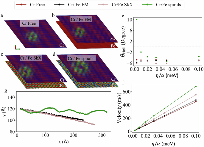
a–d Snapshots of the AFM skyrmion at Cr layer in four different cases: a Cr freestanding case, where the magnetic interactions with Fe layer are not included (AFM skyrmion radius is 2 nm); b Fe interactions are included with a finite magnetic field saturating Fe into a FM state (AFM skyrmion radius is 2.1 nm), while c a weaker magnetic field leads to a skyrmion lattice (SkX) which slightly enlarges the AFM skyrmion (radius of 2.5 nm); d in the absence of a magnetic field spirals emerge at Fe layer (AFM skyrmion reaches a radius of 3.2 nm). e Impact of the current parameter ratio η/α on the skyrmion Hall angle, and f on velocity. g The trajectories of the AFM skyrmion for cases in (a–d) with η/α = 0.01 meV.
As mentioned before, AFM skyrmions exposed to spin-polarized currents via STT, typically do not experience a SkHE41,42,43,44,77 while their velocity is expected to be proportional to η/α in the case of CPP injection77. Surprisingly, our AFM skyrmions exhibit an unexpected dynamical behavior, deviating from conventional expectations. Independently from the Cr–Fe interaction and the nature of the magnetic state pertaining to the Pd/Fe film, the Hall angle is, generally, found to be around −5° (negative sign means the deviation is clockwise), which remains consistent across various η/α values (Fig. 2e). Deviations occur, however, for weak driving forces (small η/α) when Cr is placed atop Fe spin spirals. Indeed, the AFM skyrmions display irregular scattered trajectories as depicted in Fig. 2g, due to uncontrolled scattering at various spin textures emerging in Fe. In this particular case, the extraction of the Hall angle is not trivial, since the skyrmion trajectories are not straight. Interestingly, the Fe spirals can deflect the AFM skyrmions strongly, which can lead to effective Hall angles larger than 10°, as calculated up to average distances of about 90 nm.
The velocity of the skyrmions is linear with η/α, with the largest speed found when Fe hosts a spirals state (Fig. 2f). Intriguingly, the Cr–Fe interaction, in general, favors large skyrmion velocities, which can be traced back to the size of the skyrmions. Indeed, the Cr–Fe interaction enlarges the diameter of the AFM skyrmion, which is known to increase its velocity52,78, as unveiled in the following analysis. Examples of skyrmion trajectories are shown in Supplementary Movies 1–3.
Figure 2e, f is just the tip of the iceberg. By analyzing the skyrmion dynamics as a function of the direction of the applied current, we unveil a rich anisotropic response: both the skyrmion Hall angles and velocities are modified and we identify directions along which the SkHE cancels out. Before discussing the anisotropic current-driven dynamical response, we briefly address the origin of this behavior, which is induced by the ellipticity of the AFM skyrmions emerging in Cr/Pd/Fe/Ir(111) surface. By carefully scrutinizing the AFM skyrmions, one can identify an elliptical shape. For instance, the single AFM skyrmion shown in Fig. 3c has a major and minor axis of 2.2, and 1.8 nm, respectively. Upon formation of a double AFM skyrmion, the shape of the skyrmions remains elliptical. The size of the skyrmions forming the solitonic dimer, increases significantly, enlarging both the major and minor axes of the skyrmion building blocks to 3 nm and 2.4 nm, respectively. The origin of the observed ellipticity can be traced back to the anisotropic magnetic environment experienced by the spins residing in the AFM skyrmion due to the interplay between the neighboring exchange interactions in the triangular lattice. The lattice can be decomposed into four sublattices carrying distinct magnetic states (a more detailed analysis is provided in Supplementary Notes 1 and 2 and Supplementary Fig. 2). Phenomenologically, one can demonstrate that by tuning the underlying interactions, the skyrmions can be reshaped into an isotropic form50. We note that this is clearly a material dependent property.
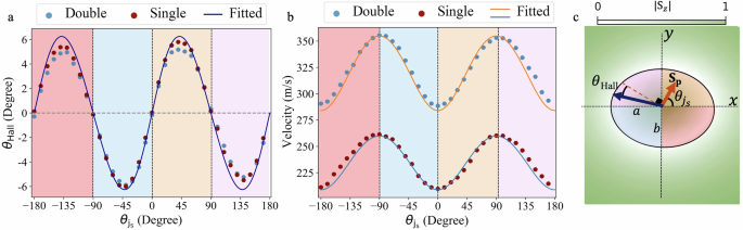
For conciseness, we consider here as an example the Cr freestanding layer case. a The skyrmion Hall angle and b the absolute value of the velocity of AFM skyrmions as a function of the angle ({theta }_{{j}_{s}}) between the current polarization direction and the major ellipse axis, for single (brown) and double (blue) AFM skyrmions, with η/α = 0.05 meV. c Schematic representation of the AFM skyrmion showing an elliptical shape, with a long (short) axis defining the x axis (y) axis. The angles associated with the spin polarization of the current SP and the SkHE are displayed. The colored regions within the ellipse correspond to those shown in (a, b).
Directionality of the current-driven elliptical AFM skyrmions
To explore the anisotropic current-driven response of the AFM skyrmions, we focus on the case of the freestanding Cr layer, i.e., with the Cr–Fe interaction switched-off. This is also representative of the behavior found when the interaction is switched on, while the Fe film hosts either the skyrmion lattice or the saturated FM state. As an example, we inject a current with η/α = 0.05 meV, but varying systematically the angle between the in-plane current and the major axis of the ellipse, ({theta }_{{j}_{s}}), which is represented by the dashed orange line in Fig. 3c.
The skyrmion Hall angle, as a function of ({theta }_{{j}_{s}}), is illustrated in Fig. 3a, which clearly shows an oscillating behavior, for both the single (brown) and double (blue) AFM skyrmions, with color-coded regions corresponding to colored areas depicted in Fig. 3c. Figure 3a shows that θHall is suppressed when the current is polarized along the two ellipse axes. It reaches the maximum value of about 6° when ({theta }_{{j}_{s}}) = 42°. Notably, it is not only the Hall angle that changes with ({theta }_{{j}_{s}}); the absolute value of the velocity of AFM skyrmions also varies as shown in Fig. 3b, exhibiting the maximum (minimum) velocity when the skyrmions move along the ellipse major (minor) axis. Interestingly as depicted in Fig. 3a, double and single AFM skyrmions show the same Hall angle when subjected to the same polarized currents. However, the double AFM skyrmion moves faster than the single one (Fig. 3b).
Thiele equation for elliptical AFM skyrmions
To investigate these intriguing findings further, we analyze the Thiele equation79 governing AFM skyrmions43,51,80,81 driven by CPP42,77,82, simplified to the particular system that we are investigating (see more details in Supplementary Note 3):
The gyrovector cancels out and thus does not contribute to the Thiele equation of AFM skyrmions. Moreover, the effective mass emerging for AFM skyrmions is neglected due to the large AFM exchange interaction51,81 (see Supplementary Note 3). v denotes the absolute value of the skyrmion velocity while ({{bf{S}}}_{p}=(cos {theta }_{{j}_{s}},sin {theta }_{{j}_{s}})) stands for the unit vector defining the spin polarization direction of the injected current. Note that the x and y axes are defined by the semi-major and semi-minor axes of the elliptical skyrmion, respectively (see Fig. 3c). ({mathcal{B}}) is the driving force tensor, and ({mathcal{D}}) is the dissipative tensor for the whole AFM skyrmion. If the skyrmions were isotropic in shape, the velocity would be perpendicular to the polarization of the current, and there would not be a SkHE.
For each building-block FM skyrmion i forming the AFM skyrmion, the associated components of the dissipative tensor83, (assuming skyrmions of identical size and shape, are given by: (({{mathcal{D}}}_{xx}^{i},{{mathcal{D}}}_{yy}^{i})=frac{{pi }^{2}}{8}left(frac{b}{a},frac{a}{b}right)), where a, and b are the semi-major and semi-minor ellipse axes, while ({{mathcal{D}}}_{yx}^{i}={{mathcal{D}}}_{xy}^{i}=0). The components of the driving force tensor are (({{mathcal{B}}}_{xy}^{i},{{mathcal{B}}}_{yx}^{i})=frac{gamma pi }{8}eta (-b,a)) and ({{mathcal{B}}}_{xx}^{i}={{mathcal{B}}}_{yy}^{i}=0). The skyrmion velocity is then given by:
where one immediately notices that, if the skyrmions were circular isotropic, the polarization of the spin current would be perpendicular to the velocity since v ⋅ Sp = 0. The propagation direction, associated with the isotropic case, defines the reference angle from which the skyrmion Hall angle is measured ({theta }_{{rm{ref}}}=arctan frac{{v}_{y}}{{v}_{x}}={theta }_{{j}_{s}}+frac{pi }{2}). Therefore, the Hall angle is evaluated from
With these findings at hand, we can explain the behavior of the AFM skyrmions. If the current is polarized along the major or minor axes of the spins (i.e., ({theta }_{{j}_{s}}) is a multiple of (frac{pi }{2})), the Hall angle cancels out, which gives rise to the extrema of the velocity given by (frac{gamma eta b}{pi alpha }) for ({theta }_{{j}_{s}}=0,pi) (minimum) and (frac{gamma eta a}{pi alpha }) for ({theta }_{{j}_{s}}=frac{pi }{2},frac{3pi }{2}) (maximum). The ratio (frac{b}{a}), which is about 0.8 for both the single and double AFM skyrmions, influences the magnitude of the Hall angle as well as the range of oscillations in the velocity. This means, with elliptical AFM skyrmions, we have two more degrees of freedom to manipulate the CPP-induced motion of the AFM skyrmions, where the skyrmion exhibits its maximum velocity when injecting currents polarized along its minor axis, resulting in a Hall free motion along the major axis. This analysis goes along with our findings, depicted in Fig. 3b, where the double AFM skyrmion with dimensions of (a, b) = (3, 2.4) nm moves with maximum velocity of 355 m/s while the single AFM skyrmion with smaller size (dimensions of (2.2, 1.8) nm), and hence slower motion according to Eq. (2), where its maximum velocity reaches 260 m/s. The maximum Hall angle is expected for ({theta }_{{j}_{s}}+pi /2=arccos sqrt{frac{b}{a+b}}), which leads to ({theta }_{{j}_{s}}=4{2}^{circ }) and θHall = 6. 2° in agreement with the numerical findings of the previous section. Notably, the impact of ellipticity on the motion of FM skyrmions subjected to spin currents was discussed in refs. 83,84,85.
Current-driven dynamics of AFM skyrmions interacting with FM skyrmions
In Fig. 2g, we unveiled that, when the Fe substrate hosts spirals with an inhomogeneous distribution of FM skyrmions, the intrinsic AFM skyrmions, driven in the Cr overlayer, exhibit typical dynamics pertaining to interactions with defects. In this section, we explore the synthetic configuration of an AFM skyrmion, interacting with a FM skyrmion through a Pd film. This scenario is trivially realized in a Cr/Pd/Fe/Ir(111) surface by applying an out-of-plane magnetic field, which reduces the size of the FM skyrmions in Fe and transforms the lattice configuration into individual topological objects. By applying a spin-polarized current, as done previously, we drive an AFM skyrmion, in the Cr film, toward a pinned FM skyrmion, hosted by the Fe layer. We consider two cases, where either the planned skyrmion trajectory passes trough the FM skyrmion, or it is shifted (see Fig. 4a, b).
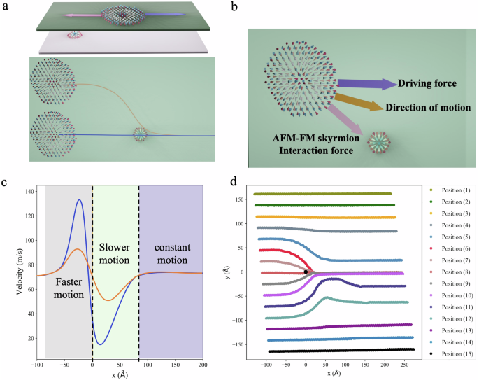
a, b Schematic representation of the forces acting on the AFM skyrmion: The driving force due to the applied spin current and the AFM–FM skyrmionic interacting induced by the FM skyrmion in the Fe layer through the Pd spacer. a Two trajectories with different starting points are illustrated. c Schematic representation of the effect of the Fe–FM skyrmion on the velocity of the AFM skyrmion with the blue and orange lines corresponding to the paths shown in (a). d The trajectory of the AFM skyrmion shown in (a) when current-driven toward a pinned FM skyrmion considering different initial positions (motion from left to right). Deflection in the motion direction occurs depending on the relative position between the AFM and FM skyrmions.
We notice that with a weak applied current, the AFM skyrmion gets pinned at the FM skyrmion (see example η/α = 0.001 meV in Supplementary Movie 4), which clearly indicates the attractive nature of the FM-AFM skyrmion interaction. A stronger current, e.g., η/α = 0.017 meV, enables the AFM skyrmion to escape the trapping FM soliton, following a roller-coaster-like motion, with an absolute value of the velocity increasing from the initial 75 to 130 m/s, which is attained when getting close to the FM skyrmion, leading to a “speeding up zone”, as shown in Fig. 4c. Once the AFM skyrmion overtakes the FM skyrmion, the velocity reduces by about 88% down to around 15 m/s, due to the FM-AFM skyrmion interaction that opposes the driving force and leads to a “slowing-down zone”. As the AFM skyrmion moves away from the FM skyrmion, only the driving force dictates its motion, resulting in a “constant motion regime”, depicted in Fig. 4c and Supplementary Fig. 3, where the velocity stabilizes at ~75 m/s.
If the AFM skyrmion is off-centered, with respect to the FM skyrmion, their mutual attractive interaction is capable of deviating the underlying trajectory, bringing the AFM skyrmion into the vicinity of the FM skyrmion, as depicted schematically in Fig. 4b and demonstrated systematically for different paths illustrated in Fig. 4d and Supplementary Figs. 3–5. Due to the AFM–FM skyrmion attraction, the AFM skyrmion deflects at the vicinity of the FM skyrmion and then continues its motion along a straight line with a velocity of 75 m/s. Intriguingly, a second deflection manifests after passing the FM skyrmion, when the AFM skyrmion starts an approach from positions (11) and (12). This signals a non-trivial energy profile of the hybrid AFM–FM skyrmionic interaction.
AFM–FM skyrmion interaction profile
To elucidate the underlying reason for the unanticipated second deflection mentioned in the previous section, we analyze the AFM–FM skyrmion interaction profile. Since the AFM skyrmion, in the Cr film, is made of two FM skyrmions oppositely oriented with respect to each other, we expect two competing interactions with the FM skyrmion in the Fe layer, as shown in the inset of Fig. 5d. The FM skyrmions, having their cores pointing in the same direction, and residing in the same ferromagnetic background, would repel each other. Conversely, the FM skyrmions having an opposite magnetic alignment would attract each other. This is clearly illustrated in Fig. 5b, and c, respectively, which shows the energy contribution of both types of coupling to the energy profile, that is obtained by rigidly shifting the AFM skyrmion all over the Cr lattice atop the FM skyrmion pinned in the center of the Fe film. The total interaction heatmap, depicted in Fig. 5a, exhibits a minimum when the AFM skyrmion overlaps with the FM skyrmion, signifying their mutual attraction. In addition, another minimum is observed when the AFM skyrmion is positioned in the lower right part of the FM skyrmion, which represents the global minimum in the rigid shift approximation. This second minimum explains the aforementioned second deflection experienced by the AFM skyrmion, as noted in the previous section.
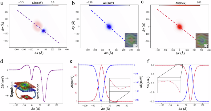
a Two-dimensional heatmap of the total energy difference resulting when rigid-shifting the AFM skyrmion all over the lattice with the presence of Fe–FM skyrmion at the center of the Fe layer. The energy difference is taken with respect to the case when the two skyrmions are not interacting. This energy difference is further decomposed into the interaction with the AFM skyrmions building blocks: the red-cored FM skyrmion residing at sublattice L2 (b), which is of an attractive nature, and the interaction with the blue-cored skyrmion residing at sublattice L1 (c), which is of repulsive nature. d Energy profile along the purple line indicated in (a), decomposed in (e) into the L2 blue and L1 red contributions. f The z component of the spin in the two sublattices L1 (blue) and L2 (red) along the purple line when the AFM skyrmion positioned at the second minimum shown in (a). Inset in (d) is a schematic representation of the nature of the interaction between the building blocks of the AFM skyrmion and the FM Fe skyrmion.
The surprising second minimum has its origin in the intrinsic asymmetric shape of the AFM skyrmion, with respect to the skyrmion core residing in one of the sublattices, as illustrated in Supplementary Fig. 6. When interfaced with the Fe–FM spins, the Cr spins, residing in the background of sublattice L1, tilt away from their initial direction, while those residing in sublattice L2 get more collinear and antiferromagnetically aligned with respect to the Fe-magnetization, see the red and blue plots respectively in Fig. 5f, obtained along the purple line in Fig. 5a, when positioning the Cr skyrmion at the second minimum. At the vicinity of the Fe–FM skyrmion, the interaction picture gets reversed, which leads to the sublattice-dependent interaction profile shown in Fig. 5e. In particular, the asymmetric profile of the AFM skyrmions, together with the magnetic interaction across the sublattices, enable an energy gain in an area of sublattice L1, where the Cr spins benefit from the AFM coupling with the core of the Fe skyrmion (see the kink in the spin profile highlighted in the inset of Fig. 5f). Unveiling the interaction profile between AFM and FM skyrmions holds significant importance, as it offers an opportunity for manipulating and regulating the trajectories and dynamics of AFM skyrmions by strategically positioning pinned FM skyrmions at the Fe layer.
Discussion
In this study, we uncovered the intricate dynamics of intrinsic AFM skyrmions subjected to perpendicular-to-plane spin-polarized currents, with a particular attention to the impact of FM skyrmions emerging in a hybrid heterostructure (Cr/Pd/Fe/Ir(111) surface) made of an AFM layer (Cr) separated from a FM layer (Fe) by a Pd spacer layer. In contrast to expectations, even for AFM skyrmions, we demonstrate the emergence of the SkHE stemming from the elliptical shape of the topological states. Both the SkHE and skyrmion velocity are anisotropic and follow well-defined dependencies with respect to the polarization direction of the applied currents. The ability to manipulate the polarization direction of spin currents provides a clear avenue for designing tracks where the SkHE either diminishes or persists. However, we would like to emphasize that while we demonstrate the SkHE for elliptical AFM skyrmions in our specific system, our findings extend beyond this particular case. As explained in Supplementary Note 2 and in our previous findings50, AFM skyrmions formed on triangular lattices hosting a RW-AFM state, tend to exhibit elliptical shapes. Moreover, achieving isotropic shape in these skyrmions requires meeting specific conditions, such as a defined ratio between exchange interaction parameters, the 1st and the 2nd nearest neighbor Heisenberg exchange interactions (J1 and J2). Therefore, our results are not confined to a singular system but rather offer insights applicable to a broader class of AFM skyrmions emerging on triangular lattices. Moreover, the presence of non-trivial magnetic states in the FM film can impact the dynamics of the AFM skyrmions by tuning both their velocity and trajectory. For instance, FM skyrmions act as pinning centers, which, depending on the applied current, can deflect AFM skyrmions. The seeding of FM skyrmions modifies the emergent hybrid AFM–FM skyrmionic interaction profile non-trivially. This profile can host several minima, offering the potential of customizing pathways for the motion of AFM skyrmions (see examples illustrated in Supplementary Fig. 7).
In summary, our study advances the understanding of AFM skyrmion dynamics and their interplay with FM skyrmions. These insights hold great promise for the development of innovative spintronic devices that harness the unique properties of AFM and FM spin textures. As the field of AFM spintronics continues to evolve, this research contributes to the foundation for efficient information processing and storage schemes, potentially revolutionizing the realm of next-generation spintronic technologies.
Methods
To simulate the trilayer of Cr/Pd/Fe, deposited on Ir(111) with fcc stacking, we employ Density functional theory (DFT). To relax the magnetic layers, we use the Quantum-Espresso computational package86. The projector augmented wave pseudopotentials from the PS Library87 and a 28 × 28 × 1 k-point grid were used for the calculations. Then, the electronic structure and magnetic properties were simulated using the all-electron full-potential relativistic Koringa–Kohn–Rostoker (KKR) Green function method88,89,90 in the local spin density approximation. The Heisenberg exchange interactions and DMI vectors were extracted using the infinitesimal rotation method91,92 with a k-mesh of a 200 × 200. More details on the simulation procedure can be found in ref. 49.
Atomistic spin dynamics
To explore the intricate dynamics of the AFM skyrmions, we conducted atomistic spin simulations. In our study, we consider a two-dimensional Heisenberg model on a triangular lattice, equipped with Heisenberg exchange coupling, DMI, the magnetic anisotropy energy, and the Zeeman term. All parameters were obtained from ab initio. The energy functional reads as follows:
with:
where i and j are site indices carrying each magnetic moments. Si is the unit vector of the magnetic moment residing at site i. ({J}_{ij}^{{rm{X-Y}}}) is the Heisenberg exchange coupling strength, being <0 for AFM interaction, between an X atom on site i and a Y atom on site j. A similar notation is adopted for the DMI vector D and the magnetic anisotropy energy K. The latter favors the out-of-plane orientation of the magnetization. In order to promote the formation of a single AFM skyrmion, independent of the Fe magnetic state’s influence; we reduced the Cr atom magnetic anisotropy from 0.5 to 0.4 meV per magnetic atom in this study. The Zeeman coupling, of the atomic spin moment μi at site i to an magnetic out-of-plane field, is described by hi = μiB.
Landau–Lifshitz–Gilbert (LLG) equation for CPP
We apply the spin-polarized CPP injection to induce the transitional motion of AFM skyrmions. In the CPP case, the current is perpendicular to the film plane, but polarized in an in-plane direction. The dynamics of the magnetization Si at the lattice site i is then governed by the extended LLG equation, which takes the STT terms into account41,42,74,75,76,
where γ is the gyromagnetic ratio, α is the Gilbert damping parameter, ({{bf{B}}}_{{rm{eff}}}^{i}propto -frac{partial {mathcal{H}}}{partial {{bf{S}}}_{i}}) is the effective field, Sp is the direction of the polarized current and
gives the amplitude of the polarized current. The quantities that determine the amplitude are the current density js, the polarization P, the saturation magnetization Ms, the Landé factor g, the magnitude of the electron charge e, the Bohr magneton μB, the film thickness d, and the gyromagnetic ratio γ. In our study, we utilize the LLG equation as implemented in the Spirit code93. We assumed periodic boundary conditions to model the extended two-dimensional system with cells containing 2002 spins. In our simulations, we used several values of η/α, ranging from 0.001 reaching 0.1 meV, with the in-plane spin polarization direction, Sp, is set at different angles as clarified earlier. All simulations were carried out at zero Kelvin.


Responses