Discriminating ferrotoroidic from antiferrotoroidic ground states using a 3d quantum spin sensor

Introduction
Since their discovery1,2,3,4,5, single-molecule toroics (SMTs) have garnered significant attention from the molecular magnetism community owing to their rich physics6,7,8,9,10,11, novel geometries12,13,14 and potential applicability to future quantum information technologies15,16. In addition, the preparation and control of molecular toroidal moments in molecules grafted to spintronics circuits17,18,19 or in STM set-ups20 has been suggested theoretically.
Presently, probing molecular toroidal states through standard experimental means is difficult since their vanishingly small net magnetic moment interacts extremely weakly with external uniform magnetic fields. Alternatively, these moments ought to interact strongly with the curl of a magnetic field ∇ × B21,22, though generating field inhomogeneities on the molecular scale is particularly challenging. Consequently, the existence of ground state toroidal moments in molecular ring systems must be inferred from experiment through computational and theoretical modelling.
Quantum spin sensors may instead offer a way to detect the miniscule magnetic fields23,24,25 associated with the imperfect cancellation (i.e. broken symmetry) of dysprosium magnetic moments in a toroidal configuration. Nitrogen-vacancy (NV) centres in diamond are typically employed in this vein26,27 though, to the best of our knowledge, a successful coupling between the remnant magnetisation of a molecular toroidal moment and a single NV centre, i.e. deposition of a Dy3 moiety on a diamond surface, has yet to be demonstrated. Trapped ions, neutral alkali atoms and Rydberg atoms mounted in vapour cells have also been suggested as room temperature, electromagnetic field sensors28,29. Accurate field sensing in these set-ups is again dependent upon close proximity of the sensor and analyte30 so how to establish an effective coupling through proper spatial localisation of the sensor and the SMT remains an open question. The development of molecular qubits that are grafted or placed in proximity to an analyte is another particularly exciting and promising approach to innocently probe weak intermolecular fields via optical or electrical readout of the perturbed energy gaps in the sensor31,32. What makes them particularly attractive for sensing is a customised, bottom-up synthetic approach that targets specific analytes individually33. While certainly the most promising candidates for next-generation quantum sensing of molecular properties, the synthesis of a molecular qubit sensor for toroidal ground state configurations has, to the best of our knowledge, not been realised to date.
Chemically grafting a transition metal ion to a molecule containing Dy3 triangular moieties may offer an experimentally feasible handle to probe for molecular toroidal moments and for the nature of intramolecular toroidal coupling between Dy3 subunits. Various coupling schemes between transition metal ions and Ln3 molecular triangles have already been realised in the literature, often in a bid to implement ferrotoroidic (FT) (con-rotating) or antiferrotoroidic (AFT) (counter-rotating) coupling of two distinct toroidal triangles, both to fine tune the extent of ground state toroidicity and to develop materials that display toroidically ordered phases in the quest for novel ferroic or multiferroic properties34,35,36,37,38,39,40,41,42. Recently, particularly strong experimental evidence was presented for a ferrotoroidically ordered phase in the quasi-1D ternary compound Ba6Cr2S1043 at around 10 K. Detailed X-ray diffraction and scanning transmission electron microscopy experiments demonstrated unequivocally that the material was composed of 1D chains of dimerised CrIII ions. Magnetic susceptibility and powder neutron scattering experiments revealed an antiferromagnetic coupling between Cr-Cr dimers resulting in a toroidal moment perpendicular to the axis of the spins. While non-collinear magnetic patterns are well known to exist in extended solid state compounds, typically arising as broken symmetry thermodynamic phases below some critical temperature, in molecules, toroidal spin textures are achieved as quantum states of collections of magnetically anisotropic atoms, typically lanthanide ions. In MLn6 compounds37,38,39, FT coupling between toroidal quantum states in each Dy3 triangular moiety has been observed, which may manifest as a ferrotoroidically ordered phase in the crystal, of course below a much smaller temperature T ~ 0.5 K. Notably, the sub-Kelvin single-crystal dynamical magnetisation experiments carried out on these molecules always employed magnetic field sweeping domains that were large enough to activate spin-flipped states on single Ln ions, leading to large variations in the molecule’s magnetic moment and hence to large steps in the magnetic profile, thus obscuring the detailed magnetic response originating from the central transition metal ion exchange coupled to the toroidal moment.
Here, we describe the synthesis and magnetic characterisation of a novel [({{rm{Cr}}}^{{rm{III}}}{{rm{Dy}}}_{3}^{,text{III},})(OH)4(iso)6(H2O)6]Cl2 ⋅ 5H2O (iso = isonicotinate) complex (1) (denoted CrDy3 in the following text); a building block towards the previously reported CrDy6 double triangle37. In addition to the prediction of a CrDy3 ground state toroidal configuration, we explain the atypical sickle-shaped magnetisation curve stemming from our μ-SQUID measurements using a dynamical master equation model that accounts for the coupled spin dynamics of the Dy3 triangle and the CrIII magnetic moment. Consequently, we demonstrate that a transition metal ion grafted to a Ln3 triangle can act as an intramolecular quantum spin sensor, sensitive to the symmetry-breaking properties of the surrounding environment by virtue of weak intramolecular interactions and propose a mechanism for the experimental discrimination between FT and AFT ground states in 3d-4f heterometallic MDy6 double triangle complexes.
Results
Synthesis and magnetic properties of CrDy3
Complex 1 is formed from the reaction of CrCl3 ⋅ 6H2O, Dy(NO3)3 ⋅ 6H2O, with isonicotinic acid in the presence of triethylamine. X-ray single crystals are grown from MeOH/Et2O to yield purple crystals, which were analysed using single crystal X-ray diffraction techniques to allow for structural elucidation. Complex 1 crystalizes in the orthorhombic space group, Pnma. Complex 1 is a tetranuclear complex consisting of three DyIII ions and a CrIII ion (Fig. 1a). The metallic core can be described as a {Dy3Cr(OH)4} distorted cubane structure with the metal ions and four OH− ions at the vertices of the cube. Alternatively, it can be viewed as a ({{{rm{Dy}}}_{3}^{,text{III},}}) triangle lying above a ‘central’ metal ion site i.e. the building block towards the previously reported CrDy6 double triangle complex37. The metallic core is stabilised by four hydroxide ions, six isonicotinate and six water ligands. Each hydroxide ion displays a μ3 bonding mode. Three of the hydroxide ligands connect the CrIII ion to two DyIII ions within a triangle, while the fourth connects the three DyIII ions within the triangle. Three of the isonicotinate ligands bridge (μ2) between two DyIII ions, while three bridge (μ2) between a DyIII and CrIII ion. Two water molecules are terminally bound to each DyIII ion. The CrIII ion is six coordinate with an octahedral geometry and a CrIIIO6 environment. The average CrIIIO6 bond length is 1.977 Å. Each DyIII ion is eight-coordinate with a triangular dodecahedron geometry. The average Dy-O bond length is found to be 2.38 Å.

a Crystal structure of 1 where Dy ions are shown in cyan, Cr in purple, O in red, N in blue, C in grey and H in white. b Stylised depiction of paramagnetic centres in CrDy3 with solid orange arrows showing the ab initio computed DyIII magnetic moments in one of the ground state vortex configurations. The translucent orange arrow indicates the direction of a remnant magnetic moment from the imperfect cancellation of the DyIII moments which couples antiferromagnetically to the (S=frac{3}{2}) CrIII spin shown in red. A schematic of the complex is shown on the right highlighting the circumscribed radius r, and the height of the complex h as well as the exchange coupling J1 between the transition metal ion and DyIII cations in the triangle, and the intratriangle dysprosium exchange coupling J2.
The dynamical magnetisation measurements reported in Fig. 2 show qualitatively different magnetisation profiles for single-crystals of CrDy3 and of the previously reported37 CrDy6 complex at a broad range of sweeping field rates using the μ-SQUID technique44. In contrast to the stepped hysteresis with a central plateau reported below for CrDy6 (as well as for the prototypical Dy3 SMT1 and several other MDy6 complexes39), the dynamical magnetisation of CrDy3 appears as an upright, sickle-shaped magnetisation curve with hysteresis loops emerging only sparingly at B ~±50 mT suggesting a molecular spin relaxation time much faster than the timescale of the sweeping field. In addition, the very tight hysteresis loops either side of B = 0 T are completely quenched at zero magnetic field despite the broad range of sweeping speeds explored.
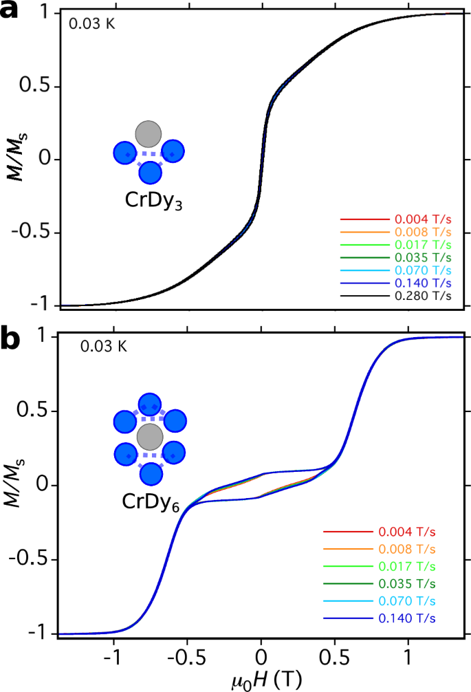
a Single-crystal magnetisation vs. field plot of complex 1 CrDy3 at T = 0.03 K for a variety of field tracing rates. b Single-crystal magnetisation of a related complex CrDy6 previously reported37. Note the lack of magnetic hysteresis in the former complex despite a faster field sweep rate than in the latter.
The origin of the stepped magnetisation profiles for CrDy6 and Dy3 have recently been discussed2,4,37 and attributed to transitions between toroidal and strongly magnetic states associated with multiple flips of dysprosium magnetic moments within the triangular subunits. The slow-relaxation, and hence emergence of magnetic hysteresis in CrDy6, was then attributed to lagging of population transfer between Dy-flipped states which occurred at a rate slower than the time evolution of the tracing magnetic field. If the same mechanism exists for CrDy3, a lack of both hysteresis loops and discrete steps in the dynamical magnetisation is suggestive of a rather different low energy Hilbert space, a stronger interaction with the dissipative environment of the crystal or a mixture of both. Alternatively, the magnetic response measured by the μ-SQUID could originate from the fast-fluctuating CrIII ion which is perturbed by the DyIII ions in the triangular subunit. We will disentangle these two possible mechanisms in the following section.
Theoretical modelling of the sickle-shaped magnetisation
To understand the striking qualitative difference between the single-crystal magnetisation profile of CrDy6 and its symmetry reduced analogue CrDy3, we first performed scalar-relativistic multi-configurational ab initio calculations to determine the electronic structure of the isolated paramagnetic ions within the CrDy3 molecule using the MOLCAS 8.0 suite45. For each of the DyIII centres, CASSCF+RASSI-SO calculations followed by an MJ decomposition of the resultant wavefunctions revealed energetically well-isolated (by ~130 cm−1), almost pure (leftvert {M}_{J}=pm 15/2rightrangle) Kramer’s ground doublets with axial g-tensors arranged around the vertices of the triangle. In particular, the g-tensor main values for each of the dysprosium ions were (Dy1: gx = 0.012, gy = 0.025, gz = 19.56), (Dy2: gx = 0.014, gy = 0.021, gz = 19.47), (Dy3: gx = 0.045, gy = 0.058, gz = 19.38). The ab initio computed magnetic anisotropy axes of the dysprosium ions are shown in Fig. 1b where an alternating out-of-plane canting angle underscores the departure from a perfect tangential arrangement of the DyIII magnetic moments. As a consequence of their strongly axial g-tensors, to a good approximation the pth DyIII ion may be considered as a semi-classical Ising spin oriented along its ab initio principal magnetic axis with its orientation labelled by the quantum number mp = ±1. The configuration of the Dy3 moiety is thus labelled by the vector ({bf{m}}doteq left({m}_{1},{m}_{2},{m}_{3}right)).
Ab initio computed Loprop and Mulliken charges for 1 are shown in Fig. 3. Considering both cases, the largest computed charges are observed on the four μ3-O atoms of the hydroxide ligands which constitute the CrDy3 core motif. As the ground state of the DyIII ion has oblate electron density, the β electron density usually lies perpendicular to the direction where large electrostatic repulsion is found. Thus in each of the DyIII ions, the main magnetic anisotropy axes (gzz) lie parallel to atoms possessing the largest charges, causing the gzz axes to adopt the approximately tangential configuration about the vertices of the triangle. In addition, the ‘larger’ charges found on the μ3-O of the hydroxide ligand, in comparison to the O atoms of isonicotinic acid and H2O ligands, influence the crystal field splitting, contributing to the rather large separation of ground and first excited state (~130 cm−1) in each DyIII ion. To ascertain whether the orientation of the H2O ligands affected the magnetic anisotropy of DyIII, we performed additional CASSCF calculations on CrDy3 with the coordinating water molecules in different orientations (see Supplementary Fig. 1 and Supplementary Tables 4–7). All orientations lead to strongly axial g-tensors and similar ground to first excited state gaps ≳120 cm−1 other than when the symmetry plane containing both O-H bonds of the water molecule was parallel to the isonicotinate ring. In that case, sizeable magnetic anisotropy was still observed however with a reduced first excited state gap ~ 80 cm−1 on one of the DyIII ions. The presence of the CrIII ion and its partial polarisation on the attached charges, relatively smaller than on μ3-O, leads to the alignment of the gzz axis of DyIII roughly in the plane of the Dy3 motif.
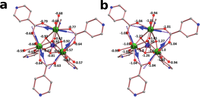
Ab initio computed a Loprop and b Muliken charges on the donor atoms of complex 1.
Similar CASSCF+RASSI-SO calculations were performed for the central CrIII ion yielding a ground state spin quartet S = 3/2 with an isotropic g tensor (Cr: gx = gy = gz = 1.96). Remarkably, our ab initio calculations predict a zero-field splitting of the CrIII ground spin manifold ~0.5 cm−1, along a magnetic axis approximately perpendicular to the triangular plane. This splitting is three orders of magnitude larger than what was previously predicted for the central CrIII ion in the higher symmetry CrDy6(NO3) complex37 and an order of magnitude larger than predicted for CrDy6(Cl)39.
To arrive at an effective model for the low-lying electronic structure for CrDy3 and its magnetic response, we appropriately adapt the established theoretical framework used to study CrDy6 and other MDy6 clusters37,39 to account for a single Dy3 triangle only. We thus account for intramolecular exchange interactions as well as magnetic dipole-dipole coupling between all paramagnetic centres in the CrDy3 molecule with the Hamiltonian Hmol = Hex + Hdip + Hzfs (details reported in the ‘Methods’ section) projected onto the basis of the lowest lying Kramer’s doublets of each of the DyIII ions and the (leftvert {M}_{{rm{Cr}}}rightrangle) spin states of the CrIII ground quartet. Using the average interatomic Dy-Dy and Cr-Dy distances, r = 2.19 Å and h = 2.57 Å as well as the ab initio computed magnetic axes, our effective model predicts a ground state toroidal configuration (pm tau doteq left(pm 1,pm 1,pm 1right)) of the DyIII magnetic moments. Owing to the imperfect cancellation of the DyIII magnetic moments (see Fig. 1b), a remnant magnetisation almost perpendicular to the plane of the Dy3 triangle results from the ground state toroidal configuration. The magnitude of the remnant magnetisation Mrem, is equivalent to that which would arise from a perfectly tangential arrangement of the DyIII magnetic moments about the vertices of the triangle with an average out-of-plane canting angle η ≈ 1°.
In Fig. 4a and b we show the experimental isothermal magnetisation at T = 2, 3, 4 and 5 K and the magnetic susceptibility (dots) and compare the resultant curves to simulations of the same quantities from our theoretical model (solid lines) with J1 = −0.4 cm−1 and J2 = −0.01 cm−1 as the only fitting parameters of our model. The theoretical curves agree particularly well with the experiments despite underestimating the experimental magnetisation at high fields (a symptom of magnetic torquing in the experiment). Despite the absence of a characteristic S-shaped powder magnetisation curve (which typically indicates a non-magnetic ground state in SMTs), the tendency of our magnetic susceptibility measurements towards χmT → 0 as T → 0 provides evidence of a weakly magnetic CrDy3 ground state in agreement with our theoretical predictions (see the low energy Zeeman diagram of CrDy3 in Fig. 4c). Notably, the exchange coupling constants predicted by density functional theory (DFT) calculations on CrDy3 did not lead to a good reproduction of the experimental magnetic measurements. The failure of DFT to extract meaningful exchange coupling constants in this case may point towards a subtlety in the electronic structure of CrDy3 that warrants further investigation. Lastly, in Fig. 4d we compare the experimental single-crystal magnetisation with our simulated magnetisation obtained from numerical integration of an adiabatic master equation. In our master equation we account for a modified spin dynamics of the CrDy3 in the presence of an oscillating applied magnetic field owing to dissipative interactions with the crystal environment e.g. spin-phonon mediated magnetic relaxation and stray-field induced quantum tunnelling mechanisms37,39. We find rather good agreement between the sickle-shaped experimental magnetisation and our theoretical prediction when the dynamically sweeping magnetic field is oriented approximately along the magnetic anisotropy axis of the CrIII spin.
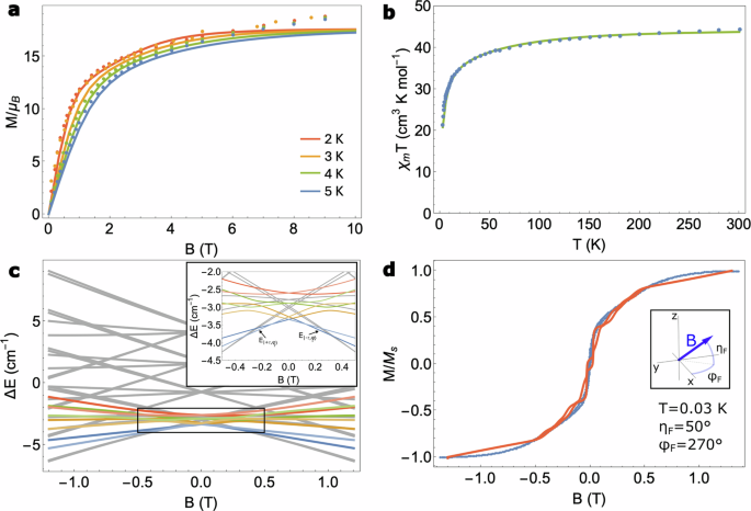
a Comparison of the experimental isothermal powder magnetisation (dots) with the simulated powder magnetisation (solid lines) at T = 2, 3, 4 and 5 K. b Comparison of the experimental zero-field powder magnetic susceptibility versus temperature (blue dots) with the simulated χmT (green solid line). c Zeeman energy levels of the thirty-two dimensional Hilbert space of CrDy3 using J1 = −0.4 cm−1 and J2 = −0.01 cm−1 obtained from fitting to (a, b). The coloured lines correspond to Zeeman energies of states with a vortex configuration of the DyIII magnetic moments (the lighter (darker) colour represents a clockwise (anticlockwise) vortex configuration). The applied field is chosen almost exactly along the intrinsic magnetic anisotropy axis of the CrIII ion which was obtained from ab initio calculations. The inset shows a zoomed-in picture of the boxed region where, at zero-field the system exhibits a doubly degenerate ground state toroidal moment in the wheel. d Comparison between the experimental single-crystal magnetisation at T = 0.03 K (blue dots) and our theoretical simulations of the single-crystal magnetisation from a master equation model (red solid line). For the simulations we found the best agreement with experiment when the field was oriented roughly along the magnetic anisotropy axis of the CrIII ion. We employed a spin-phonon coupling constant Γ = 5 × 104 cm3 s−1, a quantum tunnelling matrix element γ/ℏ = 106 s−1, a Lorentzian broadening factor λ = 1010 s−1 and a field sweep rate ω = 0.28 T s−1.
To understand the sickle-shaped magnetisation curve, we plot the time-evolution of the relevant state populations for a forward sweep of the field in Supplementary Fig. 2. At large, negative values of the applied field, magnetic states of the Dy3 wheel are activated with dominant contributions to the single-crystal magnetisation. It is worth noting that, since these states have a large magnetic moment only in the plane of the Dy3 triangle and the field is applied almost perpendicularly (along the CrIII magnetic anisotropy axis), the resultant cosine contributing to the magnetisation is comparable to the spin of the CrIII ion. Interestingly, even at B = 1 T the antiferromagnetic interaction between the CrIII spin and the magnetic states in the Dy3 wheel overcomes the energy for realignment of the CrIII spin to the applied field. As the field is swept forward, a level crossing with one of the toroidal states is reached and a fast quantum tunnelling of the magnetisation transitions the system into a pure toroidal configuration where, for weak fields, the magnetic response is dominated by the CrIII spin only. The time reversed situation occurs once the system passes through zero field and a further quantum tunnelling event transitions the Dy3 wheel back to a magnetic configuration.
Close inspection of the CrIII wavefunction amplitudes in the restricted sweeping domain where only the toroidal configurations are populated, reveal somewhat mixed CrIII wavefunctions as a result of competing interactions between alignment against the intrinsic magnetic anisotropy axis of CrIII, the weak remnant magnetisation of the Dy3 wheel and the weak applied field. This mixing is a signature of the Cr3+ spin sensing mechanism and results in a deviation of the single-crystal magnetisation from what might be expected of a free-fluctuating CrIII spin that instantaneously responds to an applied field (see the red and green curves in Fig. 5a). This deviation is even more prominent when the intrinsic magnetic anisotropy of the CrIII ion is quenched (orange curve in Fig. 5a) leading to a much stronger mixing of the CrIII spin states in this restricted field sweeping region (Fig. 5b, c) and thus represents a definitive experimental-only measure of the toroidal states in Dy3. In fact, in Supplementary Note 1, we also explore the situation wherein the sickle-shaped magnetisation of CrDy3 can be entirely explained by the response of the CrIII alone, influenced only by its intrinsic magnetic anisotropy and coupling to the remnant magnetic field of the toroidal states. The powder magnetisation measurements made on CrDy3 (Fig. 4a) did not support this hypothesis, however. In either case, the zero-field splitting in CrIII cannot be easily disentangled from the exchange anisotropy introduced by the remnant magnetic moment of the toroidal states. In the next section we will illustrate how the combination of (i) quenching transition metal sensor zero-field splitting and (ii) restricting the sweeping domain of the ac field, leads to a clear FT/AFT discrimination in MDy6 compounds.
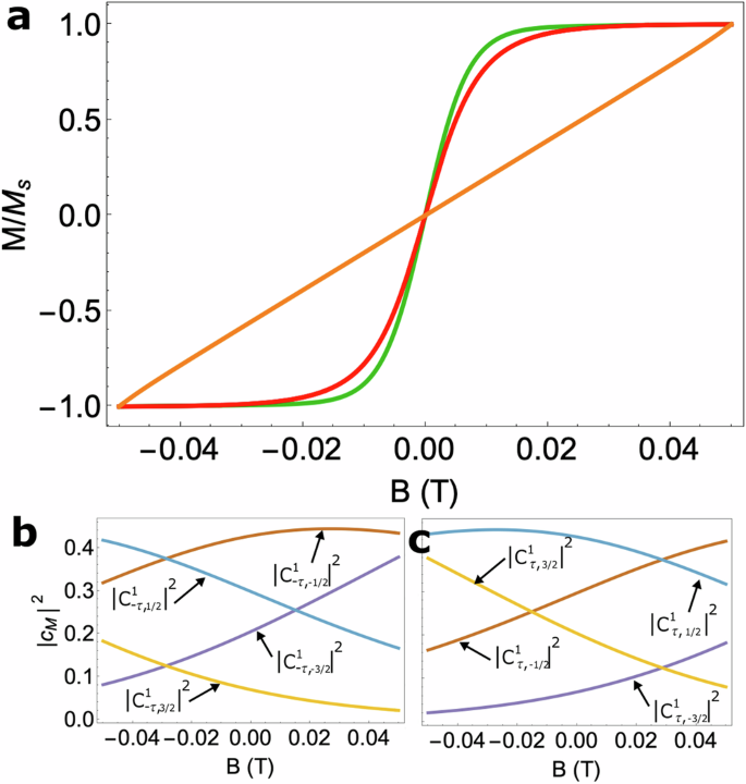
a Simulated quasi-static magnetisation in the case of a free-fluctuating spin (frac{3}{2}) i.e. a Brillouin function (red curve), the CrDy3 molecule explored in the main text (green curve) and CrDy3 without CrIII zero-field splitting (orange curve). The squared amplitudes of the ground state CrIII wavefunctions with a b clockwise and c anticlockwise toroidal configuration in the Dy3 moiety, when CrIII zero-field splitting is quenched in the restricted field sweeping regime −50 mT ≤ B ≤ 50 mT.
Sensing ferrotoroidic or antiferrotoroidic ground states in MDy6 complexes
Taking inspiration from the CrDy3 model system, we turn our attention to the detection of FT or AFT ground states in the MDy6 parent complexes37,39. Recently, the intimate correlation between the structure and ground state magnetic properties of MDy6 complexes was exposed systematically by varying the central 3d transition metal ion MIII and the counter anion (Cl− or ({{rm{NO}}}_{3}^{-})) across each complex39. Importantly, the assignment of a FT or AFT ground state Dy configuration for each complex was made possible only via theoretical models which were used to simulate magnetisation and susceptibility experiments. In the case of MIII = CrIII, a FT ground state was predicted37 that was characterised by con-rotating vortex arrangements of the DyIII magnetic moments in each triangular subunit. These magnetic moments cancel exactly owing to the inversion symmetry of the molecule resulting in a net zero remnant magnetic moment from the Dy3-Dy3 motifs. On the other hand, for MIII = FeIII, the ground state was predicted to be AFT39 thus leading to a remnant out-of-plane magnetic moment as a result of the counter-rotating vortex arrangements of DyIII moments in each triangle.
While single-crystal magnetisation measurements of these complexes were made in the aforementioned study, the sweeping domain was chosen so that dynamical transitions to strongly magnetic, Dy-flipped configurations of the DyIII moments dominated the magnetic hysteresis measurements thus obscuring the fine details of the central 3d metal ion spin dynamics. If the same measurements were made but with the sweeping range restricted only to activate states from either the ground FT or AFT configurations, then the observation of a free fluctuating central metal ion spin (Brillioun magnetisation curve) or one coupled to a remnant magnetisation (sickle-shaped magnetisation curve) would be diagnostic of a FT or AFT ground state configuration, respectively. This would of course assume no intrinsic magnetic anisotropy (i.e. zero-field splitting) of the central metal ion spin levels. Such a situation may be realised by the substitution of (S=frac{1}{2}) CuII for the central metal ion of MDy6; automatically quenching zero-field splitting effects.
Using an effective theoretical model akin to that presented above, we set-out to prove this effect for a CuDy6 complex. We describe the magnetic axes of the pth dysprosium ion in each complex as ({{boldsymbol{mu }}}_{p}=(-sin ({theta }_{p}-phi )cos (eta ),cos ({theta }_{p}-phi )cos (eta ),pm sin (eta ))) where ({theta }_{p}in left{0,frac{2pi }{3},frac{4pi }{3},frac{-pi }{3},pi ,frac{pi }{3}right},eta) and ϕ are the average angles of distortion away from a perfect tangential arrangement of the Dy moments around each triangular unit and ± corresponds to a DyIII ion in the upper and lower triangular plane of each molecule. For the purposes of illustration, we utilise in our calculation the average geometric quantities r, h, η, ϕ and the DFT computed exchange coupling J2 obtained for CrDy6(NO3) now with CrIII replaced with CuII. Accounting for the intramolecular exchange coupling and dipolar interactions, we compute the single-crystal magnetisation for J1 = −0.1 cm−1 (resulting in a FT ground state) and J1 = −1 cm−1 (resulting in an AFT ground state) in a field domain restricted to only thermally populate the FT and AFT ground manifolds of each complex.
In Fig. 6b we present simulations of single-crystal magnetisation for CuDy6 with FT and AFT Dy3-Dy3 ground configurations. At T = 0.01 K (a temperature accessible to μ-SQUID magnetometers) there is only enough thermal energy to populate the ground FT or AFT manifolds of each molecule; the two manifolds being separated in energy from a combination of intertriangle dipolar interactions and exchange coupling to the central metal ion. When a field is applied ηF = 10° out of the plane of the triangular subunits, the FT complex gives the magnetic response typical of a free-fluctuating CuII ion (i.e. a S = 1/2 Brillouin function) which remains completely insensitive to the field sweeping orientation (see Supplementary Fig. 7). In contrast, the magnetic response of the AFT complex departs from the behaviour of a free-fluctuating spin and a sickle-shaped magnetisation curve is recovered similarly to CrDy3. Notably, the magnetisation profile of this molecule is particularly sensitive to field orientation (Supplementary Fig. 7). Owing to a summation rather than a cancellation of the out-of-plane Dy3 magnetic moments in the AFT ground state, a competition emerges between the alignment of the central CuII spin moment to the remnant magnetic moment of Dy3-Dy3 and to the applied field.
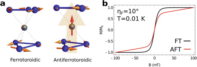
a Schematic depiction of the CuDy6 complex displaying ferrotoroidic (left) and antiferrotoroidic (right) ground state configurations in the absence of a magnetic field. The perfect cancellation of inversion related DyIII magnetic moments in the ferrotoroidic ground state leaves the central CuII spin free-fluctuating whereas in the antiferrotoroidic case the central metal ion couples to the remnant out-of-plane magnetic moment of the Dy3 subunits (transparent orange arrow). b Simulations of single crystal magnetisation at T = 0.01 K for CuDy6 with a ferrotoroidic (black) and antiferrotoroidic (red) ground state, when a field is applied ηF = 10° out of the Dy3 plane and swept in a domain restricted to probe only the ferrotoroidic/antiferrotoroidic manifolds. While the response of CuDy6 with a ferrotoroidic ground state to the magnetic field is archetypal of a free-fluctuating S = 1/2, the alignment of the CuII ion to the field in the antiferrotoroidic ground state is impeded by coupling to the remnant magnetisation of the DyIII moments.
Figure 6 b shows that the magnetisation profile of a free-fluctuating spin (associated with a FT ground state) differs significantly from a spin coupled to a remnant magnetisation (associated with an AFT ground state). Observation of these quantitatively different single-crystal magnetisation curves provides a diagnostic test for a FT or an AFT ground state in MDy6 complexes, without the need for theoretical modelling.
We also predict, in the proposed CuDy6 complex, that a FT or an AFT ground state can be sensed via spectroscopic methods such as electron paramagnetic resonance (EPR). Here we present powder EPR simulations demonstrating the distinctive lineshapes which occur from each ground state configuration and thus facilitate EPR FT/AFT discrimination. For low enough temperatures and restricted field-sweeping domains, only the FT or AFT ground configurations are thermally populated in the complex. Since EPR transitions between FT and AFT states involve the simultaneous inversion of three DyIII magnetic moments, they can be safely neglected. Thus only transitions between the spin states of the central CuII S = 1/2, which are Dy3-Dy3 configuration preserving, are allowed. The relevant Zeeman energies (and hence Zeeman gaps to be interrogated in the EPR experiment) can be expressed analytically
where ({{{Delta }}}_{,text{AFT-FT}}^{{rm{dip,inter}}}={E}_{{rm{AFT}}}^{{rm{dip,inter}}}-{E}_{{rm{FT}}}^{text{dip,inter},}) is the intertriangle magnetic dipole-dipole coupling energy difference between FT and AFT semi-classical DyIII magnetic moment configurations (see Eq. (4)). This contribution depends only on the geometry of the molecule (i.e. the values of r, h, η and ϕ) and can stabilise an AFT ground state when the out-of-plane canting angle η is non-negligible (e.g. an AFT configuration is stabilised in the CrDy6 molecule if η ≳ 10°). The exchange coupling of the CuII spin to the remnant magnetic moment in the AFT configuration leads to a term (scriptstyle{{Lambda }}=left[3{mu }_{0}{mu }_{B}^{2}gbar{mu }/left(2pi sqrt{{r}^{2}+{h}^{2}}right)-15{J}_{1}right]sin eta) in the second and third Zeeman energies reported in Eq. (1). These are sensitive both to the exchange coupling strength J1 and to the molecular geometry. Note that the ‘±’ on the right hand sides of Eq. (1) refer to the CuII spin eigenstates for each Dy3-Dy3 configuration.
On varying the parameters J1 and η in Eq. (1), three distinct low energy Zeeman spectra can be generated; these are depicted in Supplementary Fig. 8. For small canting angle η and small Cu-Dy exchange coupling J1, a FT ground state is observed with AFT doublets as first and second excited states, we refer to this situation as case 1. For larger canting angles the previous situation is reversed and the AFT doublets are both energetically stabilised, this is case 2. Alternatively, if the coupling J1 between the remnant Dy3-Dy3 magnetic moment and the quantum spin is sizeable, then a third scenario is realised where only one of the AFT doublets is stabilised at zero field. For this third case, the FT quartet is the first excited state of the system, and the second excited state is another AFT doublet.
In Fig. 7 we illustrate that each of these cases may be inferred from zero temperature, field-swept powder EPR measurements. For a FT ground configuration where the remnant magnetic moment of Dy3-Dy3 is zero, a signal appears in the EPR spectrum when the radiation frequency ν = gμB∣B∣/ℏ. Clearly this signal is isotropic with respect to field orientation and thus gives rise to a single, tight Lorentzian lineshape in the powder EPR spectrum (case 1: black curve). On the other hand, for an AFT ground configuration, a signal is observed when (nu =scriptstylesqrt{{left(g{mu }_{B}{B}_{z}-{{Lambda }}right)}^{2}+{left(g{mu }_{B}{B}_{perp }right)}^{2}}/hslash). This resonance condition is patently field orientation dependent and thus, as a consequence of powder averaging, results in a spectrum of many overlapping resonances which convolute into a greatly broadened EPR lineshape (case 2: blue curve). If the 3d − 4f exchange coupling J1 is so large that the previous resonance condition can not be met in the restricted field sweeping domain, then no signal is observed in the EPR experiment (case 3: red curve). We note finally that these three cases can be further interrogated with variable temperature and variable frequency powder EPR experiments as simulated in Supplementary Fig. 9.
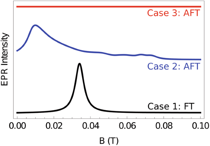
Simulated zero temperature, field-swept, powder electron paramagnetic resonance spectra of CuDy6 for the three possible ground state configurations described in the main text. Each spectrum is offset for clarity. For a ferrotoroidic ground state (black curve), a strong, narrow signal is observed archetypal of an isotropic S = 1/2. For a molecule with an antiferrotoroidic ground state and only modest 3d − 4f exchange splitting (blue curve), a much broader signal is observed. In case 3 (red curve), the exchange splitting is larger than the available photon energy and as such, no transitions at zero temperature can occur.
Discussion
We have demonstrated that the weak field region of the sickle-shaped magnetisation profile of CrDy3 results from a linear superposition of CrIII spin states which, in the absence of intrinsic magnetic anisotropy, offer a mechanism to probe the toroidal ground states of the Dy3 triangle. Owing to the sizeable zero-field splitting of the ground CrIII spin manifold, theoretical modelling is still necessary to untangle the microscopic mechanisms leading to the sickle-shaped magnetisation curve of CrDy3. Measuring the altered magnetic response of an isotropic spin system grafted to a Dy3 triangle however, offers an experimental-only method to probe the tiny intramolecular magnetic fields associated with imperfect cancellation of DyIII magnetic moments in a toroidal configuration without interfering directly with their stabilisation.
The extent to which zero-field splitting of the central transition metal ion in MDy6 contributes to the deviation of single-crystal magnetisation measurements from the case of a free-fluctuating isotropic spin, can be addressed experimentally by preparing MDy6 complexes with a central spin (S=frac{1}{2}). In the case of a 3d9 CuII ion, a configuration realised in CuDy3 polymers35, the mechanism exposed above tells us that if the single-crystal magnetisation profile behaves like a (S=frac{1}{2}) Brillouin function independent of field orientation, then this signals a FT ground state. If the single-crystal magnetisation appears sickle-shaped and strongly field-orientation dependent, this signals an AFT ground state. In general though, provided that the intramolecular exchange and magnetic dipole-dipole interactions between the central transition metal ion and the remnant magnetic moment of the Dy3 subunits are larger than zero-field splitting effects in the central transition metal ion, as is the case for CrDy6(NO3), the magnetic response of the central metal ion alone can be indicative of the FT/AFT ground state character of the molecule. Spectroscopic methods such as electron paramagnetic resonance which probe the magnetic response of the central quantum spin, also offers a qualitative measurement of the ground state Dy3-Dy3 configuration.
In summary, we have presented the synthesis, structural and magnetic characterisation of a novel CrDy3 molecule exhibiting a ground state toroidal Dy3 configuration. Theoretical modelling supported by scalar relativistic multi-configurational ab initio calculations demonstrated that the complex’s anomalous sickle-shaped magnetisation curve arises from the coupled spin dynamics of the central CrIII ion and the activation of magnetic levels in the Dy3 wheel at larger fields. The sickle-shape in particular was indicative of a fast dissipative dynamics and the compression of the Zeeman levels caused by sizeable zero-field splitting of the CrIII ground spin quartet and antiferromagnetic coupling of the CrIII spin to a small remnant magnetisation in the Dy3 triangle. After the quenching of intrinsic zero-field splitting, we suggested that the central transition metal ion of heterometallic MDy6 complexes may be employed as a quantum spin sensor for ground state FT/AFT discrimination in complementary magnetic and spectroscopic experiments.
Methods
Synthesis of CrDy3
CrCl3 ⋅ 6H2O (0.016 g, 0.1 mmol) was gently heated in acetonitrile to give a purple solution. Dy(NO3)3 ⋅ 6H2O (0.22 g, 0.5 mmol) and isonicotinic acid (0.12 g, 1 mmol) were then added. Triethylamine (0.4 mL, 0.3 mmol) was subsequently added dropwise to reveal a blue/green solution and the reaction was left to stir for 2–3 h at 70 °C. After this time the solvent was removed, and the resulting oil was redissolved in methanol. After layering the methanol with diethyl ether, pale purple/pink single crystals grew within 3–4 days. Anal. Calculated (found) for 1: CrDy3C36H50O27N6Cl2: C, 26.87 (26.67); H, 3.13 (3.19); N 5.22 (5.11).
X-ray crystallography
X-ray single-crystal structural data for 1 were collected on an Agilent Xcalibur diffractometer equipped with a fine-focus sealed tube X-ray source with graphite monochromated Mo-Kα radiation. The programme CrysAlis PRO46 was used for the data collection, cell refinement and data reduction. Complex 1 was solved by direct methods (SHELXS-97)47, and refined (SHELXL-97)48 by full least matrix least-squares on all F2 data. Crystallographic data and refinement parameters for 1 are summarised in Supplementary Table 1.
Magnetic measurements
The temperature-dependent direct current magnetic susceptibility of a polycrystalline sample of CrDy3 was measured from 1.8 to 300 K using an external magnetic field of 5 kOe with a Quantum Design PPMS SQUID magnetometer. At room temperature, χmT = 44.04 cm3 K mol−1, in good agreement with the theoretical value of 44.38 cm3 K mol−1 expected for one CrIII (S = 3/2, g = 2, C = 1.875 cm3 K mol−1) and three uncoupled DyIII ions (J = 15/2, 6H15/2, g = 4/3, C = 14.17 cm3 K mol−1). Field-dependent magnetisation measurements were performed at 2 K within a magnetic field range of 0–9 T.
Magnetisation measurements on a single crystal were performed with an array of μ-SQUIDs for 1. This magnetometer works in the temperature range of 0.02 to ~7 K and in fields of up to 1.4 T with sweeping rates as high as 10 T s−1, along with a field stability of 1 T. The time resolution is ~1 ms. The field can be applied in any direction of the μ-SQUID plane with precision much better than 0. 1° by separately driving three orthogonal coils. In order to ensure good thermalisation, the single crystals were fixed with Apiezon grease.
Computational details
Using MOLCAS 8.045, ab initio calculations were performed on the DyIII ions using the crystal structure of CrDy3 in order to find the anisotropic nature of all Dy centres. While performing the single-ion calculation on each Dy centre, we substituted neighbouring Dy ions with a diamagnetic LuIII ion and a paramagnetic Cr ion with diamagnetic ScIII ion. Relativistic effects are taken into account by employing the Douglas-Kroll-Hess Hamiltonian49. The spin-free eigenstates are achieved by the Complete Active Space Self-Consistent Field (CASSCF) method50. The basis sets were taken from the ANO-RCC library for the calculations. We have employed the [ANO-RCC…8s7p5d3f2g1h.] basis set for Dy atoms, the [ANO-RCC…6s5p3d2f1g.] basis set for the Cr atom, the [ANO-RCC…3s2p.] basis set for C atoms, the [ANO-RCC…2s.] basis set for H atoms, the [ANO-RCC…3s2p1d.] basis set for N and O atoms, the [ANO-RCC…4s3p2d.] basis set for the Sc atom and the [ANO-RCC…7s6p4d2f.] basis set for Lu51. In the first step, we run a guessorb calculation using Seward module to create the starting guess orbitals. Here, we included nine electrons across seven 4f orbitals of the DyIII ion. Then using these guess orbitals, we have chosen the active space based on the number of active electrons in the number of active orbitals and carried out the SA-CASSCF calculations. Here, the Configuration Interaction (CI) procedure were computed for DyIII ion and considered twenty-one sextet excited states in the calculations to compute the magnetic anisotropy. All the excited states corresponding to the sextet state have been computed in the CASSCF module to calculate the spin-orbit coupled states. Moreover, these computed SO states have been considered in the SINGLE_ANISO52 programme to compute the g-tensors. The g-tensors for the Kramers doublets of DyIII were computed based on the pseudospin (S=frac{1}{2}) formalism52.
Additionally, the ab initio CASSCF calculations were performed to calculate the g-tensor for CrIII in complex 1. Here, the active space for CASSCF calculations comprises five CrIII-based orbitals with three electrons in them (d3 system; CAS(3,5) setup). We considered 10 quartet excited states and 40 doublet excited states for CrIII ion52.
Along with Mulliken charges, we also used the Loprop charges to analyse and understand the direction of magnetic anisotropy, which can be computed like a charge, a component of the dipole moment or an exchange-hole dipole moment, is localised by transforming the property of two centres53.
DFT calculations were performed using the B3LYP functional54 implemented in the Gaussian 09 quantum chemistry suite55. The dysprosium ions in CrDy3 were replaced with spin-only GdIII ions. We used the double zeta quality Cundari-Stevens effective core potentials for the Gd atoms and the TZV basis set for all others. We performed a series of single point energy calculations, first converging to the high spin state of CrGd3 and then to broken symmetry states associated with the complete inversion of α to β spin density in valence orbitals localised on the paramagnetic centres. With reference to the Heisenberg-Dirac-van Vleck Hamiltonian, we generate a system of linear equations for the exchange couplings in terms of the high spin and broken symmetry single point energies which, upon rescaling the solutions by SDy/SGd and (scriptstyle{left({S}_{{rm{Dy}}}/{S}_{{rm{Gd}}}right)}^{2}) respectively, yields the values J1 = 0.3 cm−1 and J2 = −0.1 cm−1.
Theoretical model
To model the interactions between the paramagnetic ions in CrDy3 and thus simulate its magnetic properties, we account for intramolecular exchange interactions as well as magnetic dipole-dipole coupling between the paramagnetic centres in the molecule, the zero-field splitting of the CrIII ion and a coupling to an external magnetic field with the Hamiltonian
This Hamiltonian is projected onto the basis of the lowest lying Kramer’s doublets of each of the DyIII ions and the (leftvert {M}_{{rm{Cr}}}rightrangle) spin states of the CrIII ground quartet leading to a 32-dimensional Hilbert space of states (leftvert {bf{m}},{M}_{{rm{Cr}}}rightrangle doteq leftvert {m}_{1},{m}_{2},{m}_{3},{M}_{{rm{Cr}}}rightrangle). We choose a quantisation axis for the CrIII ion collinear to the applied magnetic field.
The exchange coupling Hamiltonian reads
where Sp and SCr are the spin angular momentum operators for the pth dysprosium ion and the chromium ion, respectively, with J1 and J2 denoting the appropriate exchange coupling constants for Dy-Cr and Dy-Dy interactions. To account for intramolecular magnetic dipole interactions, we implement the well known magnetic dipole-dipole interaction Hamiltonian
where μ0 is the vacuum permeability, Mp is the magnetic moment of the pth ion, Rpq is a vector connecting the ions p and q and the sum ranges over all DyIII and CrIII ions.
The zero-field splitting of CrIII is well described by the Hamiltonian
where ({{bf{e}}}_{i},iin left{x,y,zright}) are unit vectors specifying the ab initio determined magnetic anisotropy axes of the ion and D = 0.25 cm−1 and E = 8 × 10⁻³ cm−1 are the axial and rhombic zero-field splitting parameters, respectively, also taken from the ab initio calculations. Finally, the Zeeman Hamiltonian reads
where ({bf{B}}=left(cos ({phi }_{F})cos ({eta }_{F}),sin ({phi }_{F})cos ({eta }_{F}),sin ({eta }_{F})right)) and ηF, ϕF define the orientation of the applied magnetic field.
We account for a coupling between the magnetic subsystem, lattice vibrations and stray fields causing DyIII spin flips via the Redfield master equation for the reduced density matrix populations37,39
expressed on the instantaneous energy eigenbasis of Eq. (2). The time-evolution of ρm is determined both by Wk→m(t) and Ωk↔m(t) which account for spin-lattice mediated magnetic relaxation and stray-field assisted quantum tunnelling of the magnetisation from state k to state m owing to spin flips of the DyIII magnetic moments. A detailed explanation of these rates and their derivations can be found in ref. 37. Upon numerical integration of Eq. (7), we calculate the single-crystal magnetisation as
where (hat{{bf{n}}}) is a normal vector along the direction of the applied magnetic field.
To simulate the powder EPR spectrum of MDy6 we employ the Fermi golden rule to calculate radiation-induced transitions between magnetic states (leftvert irightrangle) and (leftvert frightrangle) according to
where (leftvert irightrangle) and (leftvert frightrangle), like the energy spacing ({omega }_{fi}=left({E}_{f}-{E}_{i}right)/hslash), implicitly depend upon ∣B∣ as well as on the relative orientation of the molecule to the applied magnetic field. Pf and Pi are the Boltzmann populations of states i and f, M is the total magnetic moment of the polynuclear cluster and e⊥ is a normal vector specifying the direction of radiation propagation, taken here to be perpendicular to the applied field in the lab frame. For a given direction and magnitude of the applied field, Eq. (9) is summed over for all initial and final states (leftvert irightrangle) and (leftvert frightrangle). For the powder averaging, the total signal I = ∑fiIi→f is averaged over the unit sphere using Lebedev quadrature.


Responses