Dynamic bendable display with sound integration using asymmetric strain control of actuators with flexible OLED

Introduction
Flexible electronics overcome the limitations of traditional rigid electronics, which are primarily used in flat-surface applications, by offering high adaptability to various flexible environments such as randomly shaped curved or deformed surfaces. As user demands for organic user interface (OUI) continues to grow in human-electronics interactions1, flexible displays play a crucial role in conveying information between device and user, driving the advancement of flexible electronic technologies. Therefore, shape-deformable displays such as foldable, bendable, rollable, and stretchable are emerging as the next generation of display technology, garnering significant research attention2,3,4,5, and some have already achieved commercial success. Exploiting the merits of flexible form factors, deformable displays are maximizing user convenience and form factor, and emphasizing thin, compact, and lightweight designs6. For enhancing the user-interaction experience and effective information delivery, various elements such as sensors, speakers, and actuators are being integrated into these displays7,8,9,10,11. Briefly, a flexible multifunctional form factor that maintains intrinsic thinness and flexibility is essential.
However, to fully implement deformable displays, technical challenges (such as mechanical embodiments or hinges) must be overcome. Bendable displays provide a wider field-of-view and enhance user immersion by allowing on-demand changes in the curved screen, but current methods typically involve direct-force application to the display panel to induce bending, such as wire attachments to the display panel or physically folding the display panel to transform a flat screen into a bendable display12,13. Additional mechanical embodiments are often required to wind the wires or push the panels. These devices are rigid and bulky and reduce display flexibility, increase its thickness, and limit deformation into various shapes. Here, the form-factor changes involve shape changes between the flat and simple ‘U’-shaped curved states—diminishing the freedom of the flexible-display form factor and constraining the original intent of the OUI. These are significant technical limitations that must be overcome to realize future displays that pursue more various shape changes with flexibility, portability, and compact design14. Therefore, research must aim to enhance the display-panel flexibility and deform the shape without compromising the overall display flexibility.
Electroactive polymer (EAPs) actuators can be considered to address the above challenges in bendable display techniques and to circumvent mechanical-hinge systems. EAPs are lightweight and flexible and can deform in response to electrical signals. Dielectric elastomers (DEs) are notable for their excellent in-plane stretching and stability, making them suitable for various applications. DE actuators (DEAs)—formed by placing compliant electrodes on the top and bottom of a DE—strain and produce sound under application of varying input frequencies15,16. Recently, electrically induced structural color changes have been controlled through strain engineering. Positive strain and electrically induced-shape changes result in expanding DEAs with compliant electrodes17,18,19. However, the directional strain control using DEAs is limited by the DE isotropic characteristic owing to the Maxwell stress (left(right.{sigma }_{z}=-frac{1}{2}{{cdot }}{rm{varepsilon }}{{{cdot E}}}^{2}), where ε is effective dielectric value of DEA under effective electric field E)20.
On the other hand, bidirectional strain switching uses poly(vinylidene fluoride) (PVDF), a prominent piezoelectric EAP that converts electrical energy into mechanical energy and vice versa based on the piezoelectric-coupling effect (S = d·E, where S is the strain, d is the piezoelectric coefficient and E is the electric field)21,22. The positive or negative strain changes can be controlled along the lateral direction based on the polarity of the electric field applied to the PVDF. Moreover, the electrically induced-strain change in PVDF is sufficiently fast to cover the sound frequency-level response owing to the piezoelectric-coupling effect23,24,25,26 beyond the slow, shape-changing actuations in direct-current (DC) or low-frequency alternating-current (AC) signals27,28,29. Single PVDF actuators—with electrodes formed on the upper and lower surfaces of the PVDF—can exhibit electromechanical behaviors (such as deformation in the in-plane direction) depending on the relative directions of the PVDF polarization and the applied electric field30,31,32. However, during a single PVDF actuator operation, the effective deflection along the out-of-plane direction is limited again because of the symmetrical deformation in the in-plane direction.
A heterogenous-structured PVDF of unimorph actuator can be fabricated by attaching an inactive layer that does not respond to external stimuli and resists deformation33,34. The combination of the shape-maintaining property of the inactive layer and the dynamic, positive or negative strain induced by the in-plane PVDF actuation can result in asymmetrical and unbalanced deformation along the vertical structure of the PVDF actuator. Therefore, by using this structure, enhanced vertical out-of-plane deflections can be achieved, when compared with a single PVDF actuator without an inactive layer. Moreover, considering the direct and rapid actuation of piezoelectric coupling, bidirectional out-of-plane deflections can operate at frequencies ranging from less than 1 Hz to several tens of kilohertz, enabling the functionalization of acoustic sound.
In this study, we propose a novel technique for implementing a dynamically and variably shaped bendable display with an added speaker-sound function, using a PVDF actuator laminated on an inactive and flexible plastic-organic light-emitting diode (OLED) display. Unlike conventional flexible displays that require additional mechanical bending hinges and rigid components for speaker exciters, a thin, lightweight, and deformable display capable of multiple shapes with integrated sounds was developed while maintaining overall flexibility. By attaching an actuator made from 40-μm-thick PVDF films to an inactive layer comprising a flexible plastic-OLED display panel, we induced dynamic display bending through the application of electrical signals to the actuators, with no need for additional devices or accessories. Using a strain-engineering approach to control the positive strain (expansion) and negative strain (compression) of a single PVDF actuator through separately controlled electrical signals, we experimentally achieved bidirectional actuation and more complex transformations into multiple shape forms. Moreover, we investigated the electro-acoustic properties of the bidirectionally actuating bendable OLED display under high-frequency AC signals, as it rapidly and repeatedly generated positive and negative strains, thereby producing sound with shape bending deformation as well. The inactive layer of the plastic-OLED display panel attached to the PVDF actuator functions as a diaphragm, enhancing the electro-acoustic performance when compared with that using the PVDF actuator alone35. By integrating sound and electrical bending signals into a single operational signal, we developed a dynamic bendable display that simultaneously generates sound while bending in a practical 6-inch OLED display. Our research objective was to address the technical challenges associated with existing bendable displays by employing flexible actuators and multifunctional display technology. This approach enables the creation of a bendable display with integrated sound functionality through signal adjustment, ultimately enhancing user experience and improving human-machine interaction while maintaining the overall flexibility of the display.
Results
Mechanism of multifunctional bendable display with sound integration
Figure 1 illustrates the operational mechanism of a dynamic, multifunctional bendable display that incorporates an inactive display and an active actuator to achieve simultaneous shape bending and sound production. The active part employs an actuator made of thin, flexible PVDF layer that respond to the electric field; the inactive part comprises a flexible, plastic-OLED display panel for implementing a bendable display (Fig. 1a). A dynamic and complex shape-bendable multifunctional display integrated with sound can achieve multiple functionalities simultaneously by controlling the frequency range of the oppositely polarized signals applied to the fast-responding PVDF actuator. When a low-frequency signal was applied, the hybrid, flexible OLED display deformed slowly, changing its shape; when a high-frequency signal (in the acoustic range) was applied, deformation occurred rapidly, and the hybrid OLED generated sound by vibrating. During the operation, the hybrid OLED functioned as a sound-enhancing diaphragm. The electromechanical characteristics were observed on the application of an electric field to a cap-structured actuator with electrodes formed on the upper and lower surfaces of a PVDF layer (Fig. 1b and Supplementary Fig. 1).

a Representation of the bendable display with sound functionality. b Mechanism of deformation of a single PVDF actuator with no inactive layer, determined by the relative direction of polarization and the electric field. c Mechanism of out-of-plane deformation of the hybrid actuator with an inactive layer, also dependent on the relative direction of polarization and the electric field.
A PVDF actuator without an inactive layer is referred to as a single PVDF actuator. An electric field in the same direction as the +Z-axis polarization direction is termed a positive electric field, whereas an electric field in the opposite direction is termed a negative electric field. We conducted strain engineering by controlling the direction and magnitude of the electric field applied relative to the +Z-axis polarization direction. By applying an electric field in the same direction (+Z) or the opposite direction (−Z) relative to the polarization direction of the PVDF actuator. When an electric field was aligned with the polarization direction, the PVDF chains elongated, causing the actuator to contract in the thickness direction and expand in the planar direction, leading to positive strain. Conversely, when the electric field was applied in the opposite direction, the PVDF chains contracted, resulting in expansion in the thickness direction and contraction in the planar direction, thereby inducing negative strain. To maximize strain while preventing dielectric breakdown in the PVDF actuator, the magnitude of the applied electric field was carefully controlled as a critical parameter. However, the out-of-plane deflection in this structure was limited owing to the single PVDF actuator that undergoes symmetrical deformation in the in-plane direction. Figure 1c illustrates the bending mechanism in the out-of-plane direction when an inactive layer was attached to a single PVDF actuator undergoing positive or negative strain in the planar direction. When one end of the hybrid actuator was fixed and an electric field was applied, the PVDF attached below experienced either a positive or negative strain, depending on the electric-field polarity. During this process, the inactive layer attached above resisted the deformation change, causing significant asymmetry of deformation along the vertical structure, which consequently resulted in opposite deflections in the +Z or −Z-axis direction. The deformation characteristics of such PVDF hybrid actuators can be utilized in various ways depending on the frequency of the applied electrical signal. When a low-frequency electric field is applied, positive or negative deformation is induced, leading to shape transformation in the +Z or −Z direction. In contrast, when a high-frequency electric field is applied, this deformation repeats rapidly. This rapid and repetitive deformation over audible frequency range causes the actuator to vibrate thin and flexible OLED display, stimulating the surrounding air and generating direct sound from OLED. Considering that both shape deformation and sound generation can be achieved in a single device depending on the frequency range of the applied signal, it is possible to develop a multifunctional flexible display that integrates shape deformation and sound functions while maintaining a thin and flexible form factor.
Enhanced bidirectional deformation of hybrid structure including inactive layer
The electromechanical characteristics of the heterogeneously hybrid actuator in response to an electrical signal are shown in Fig. 2. The hybrid actuator utilized a heterogeneous structure, with a PVDF film polarized in the upward direction serving as the active layer, and a polyimide film as the inactive layer. Note that the inactive polyimide film was same as the substrate of plastic OLED. Both layers were bonded using an optically clear adhesive (OCA) film. Practically, polyimide is used as the substrate for flexible OLED, and the OCA film is included in the OLED display panel. The thicknesses of the materials used in the hybrid actuators are listed in Supplementary Table 1. The hybrid actuator, laminated on an inactive layer, was designed with a length-to-width aspect ratio optimized to maximize the deflection (Supplementary Fig. 2). As seen in Fig. 2a, the hybrid actuator demonstrated bidirectional bending from its initial flat state, depending on the applied electric-field direction. When a negative electric field was applied, the PVDF attached to the back underwent negative strain, causing the hybrid actuator to deflect to the right; when a positive electric field was applied, the PVDF experienced a positive strain, causing the hybrid actuator to deflect to the left. To evaluate the bending performance, quantitative measurement of the maximum displacement in the Z-axis direction (δz), as a function of the electric field applied to the hybrid actuator, was performed using a laser displacement sensor. The hybrid actuator exhibits bidirectional bending, with positive +δz and negative −δz corresponding to the positive and negative directions of the electric field relative to the zero-field state, respectively (Fig. 2b).
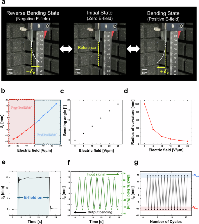
a Actual images of the hybrid actuator. Under positive electric fields, the actuator is displaced upward, and under negative electric fields, it displaced downward. b Maximum deflection of actuator as a function of the applied electric field. c Maximum bending angle of actuator when subjected to an applied electric field. d Radius of curvature as a function of applied electric field. e Maximum deflection stability of the actuator at 25 V μm−1. f Time dependencies of the maximum deflection (black line) and of the applied electric field (green line) at 0.3 Hz. g Cycling testing of the actuator operated at 25 V μm−1. The dimension of the actuator was 10 mm × 50 mm (width × length).
The results indicate that δz increases linearly with the magnitude of the electric field. This observation is consistent with the theoretical-beam equations for a unimorph piezoelectric actuator, which indicate that deflection is proportional to the applied electric field33,36,37. Figure 2c, d evaluates the performance of the hybrid actuator using additional variables: maximum bending angle and radius of curvature, as the electric field is increased from 0 to 25 V μm−1 in 5 V μm−1 increments. As shown in Fig. 2c, the maximum bending angle increased linearly with the magnitude of the electric field, similar to δz, reaching 18° at 25 V μm−1. In addition to the deflection and bending angle, the radius of curvature was utilized as a performance indicator from a display perspective, providing a comprehensive evaluation of the performance of the actuator38,39. The radius of curvature R, which is the reciprocal of the curvature of the hybrid actuator, decreased with increasing electric field strength, reaching 74.45 R at 25 V μm−1 (Fig. 2d). The reduction in the radius of curvature indicated greater bending of the hybrid actuator as the electric field increased40. Figure 2e–g shows the responses of the hybrid actuator to electrical signals. When a signal of 25 V μm−1 was applied, the hybrid actuator responded quickly to the external signal, and δz remained stable over time with no performance degradation (Fig. 2e). When an AC signal of 0.3 Hz and 25 V μm−1 was applied to the hybrid actuator, δz varied in real time with the external input signal without any delay in the output bending (Fig. 2f and Supplementary Video 1). In addition, the hybrid actuator operated reliably over 15 deformation cycles and exhibited stable, bidirectional actuation (Fig. 2g). Therefore, considering that the inactive polyimide layer is the same material as the plastic OLED substrate, a further hybrid structure could leverage the plastic OLED itself as the inactive layer within the hybrid actuator design.
Multiple-shape transformation of devices
To transform the single bending mode into a more complex, multi-shape configuration, the PVDF layer was further strain engineered (Fig. 3). In the initial state, with no electric field, both the left and right sides of device remained flat. Upon application of an electric field, the devices transformed into U- and inverted U-shaped or S- and inverted S-shaped configurations (Fig. 3a, b and Supplementary Video 2). Figure 3c illustrates the structure and mechanism of the device that transforms into U-shaped (U) and inverted U-shaped ((cap)) configurations. Two identical, single PVDF actuators with upward polarization direction were attached to the left and right sides of the inactive layer, which did not respond to the electric field, resisted this deformation, using OCA films. The mechanism of the U-shaped (U) and inverted U-shaped ((cap)) forms of the device follows: when the center of the inactive layer was fixed and an upward electric field was applied, a positive strain occurred in the PVDF on both sides, causing the device to bend upward into an inverted U-shape. When a downward electric field was applied, a negative strain occurred in the PVDF on both sides, causing the device to bend downward into a U-shape (Supplementary Fig. 3a). In Fig. 3d, the deflection (with varying electric fields) of the left and right sides of the device, which transformed into U-shaped (U)- and inverted-U-shaped ((cap)) configurations, is observed. As the electric field increased from −25 to 25 V μm−1, the δz of the left and right sides increased linearly with the magnitude of the electric field. Figure 3e shows the maximum bending angles of the left and right sides as functions of the electric field. Similar to δz, the maximum bending angle of the left and right sides increased linearly with the magnitude of the electric field. The symmetrical deformation of the device into U-shaped (U) and inverted U-shaped ((cap)) configurations was because of the identical single PVDF actuators attached on both sides, which exhibited the same behavior in response to the electrical signal.
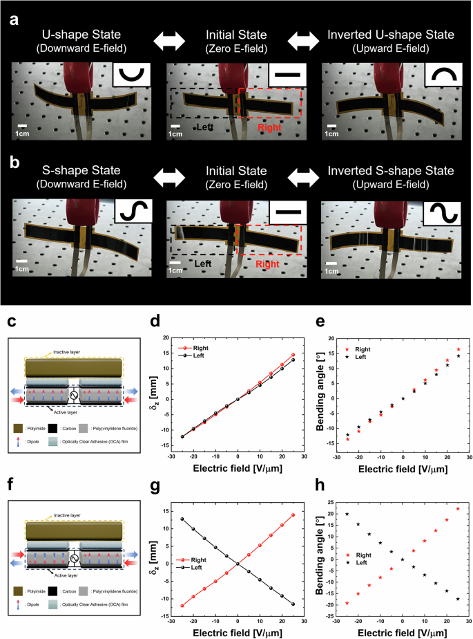
a, b Snapshots of the devices deforming from a flat shape to U-shaped (a) and S-shaped (b) configurations upon application of upward or downward electric fields. c Structure of the U-shaped device. d Maximum deflection as a function of the applied electric field for U-shaped device. e Maximum bending angle as a function of the applied electric field for U-shaped device. f Structure of the S-shaped device. g Maximum deflection as a function of the applied electric field for S-shaped device. h Maximum bending angle as a function of the applied electric field for S-shaped device.
The S-shaped (S) and inverted S-shaped (Ϩ) configurations were implemented; their structures and mechanisms are shown in Fig. 3f. The device consists of two single PVDF actuators, each with a different polarization direction. These actuators were attached to the left and right sides of the inactive layer using OCA films. When the center of the inactive layer was fixed and an upward electric field was applied, the PVDF on the right with upward polarization experienced positive strain, whereas the PVDF on the left with downward polarization experienced negative strain. Because of different asymmetrical deformation between the fixed inactive layer and positive or negative strain change of the PVDF, the right-side bends upward toward the inactive layer and the left side bends downward toward the PVDF layer, resulting in an inverted S-shaped (Ϩ) configuration. Conversely, when a downward electric field is applied, the left and right sides of the device perform actions opposite to the upward electric field, resulting in an S-shaped (S) configuration (Supplementary Fig. 3b). As shown in Fig. 3g, when the electric field increases from −25 to 25 V μm−1, the δz of the left and right sides changes oppositely from 0 V μm−1. As shown in Fig. 3h, the maximum bending angles of the left and right sides changed in the same manner. The device that transforms into S-shaped (S) and inverted S-shaped (Ϩ) configurations exhibits asymmetrical deformation because of the different structures of the single PVDF actuators on each side, which respond oppositely to the electrical signal.
Implementation of dynamically bendable display
To explore its practical applications further, we developed a dynamic, bendable display incorporating a single PVDF actuator integrated with a plastic-OLED display. As shown in Fig. 4, a dynamic, bendable display responsive to electrical signals was fabricated by attaching a single PVDF actuator behind a 6-inch flexible OLED display panel that was used as the inactive layer. To further increase the maximum deflection at the same voltage, the electromechanical characteristics were compared by varying the number of PVDF layers used in the actuator, as shown in Fig. 4a–c. The structures of the bendable displays with a single PVDF layer and two PVDF layers are illustrated in Fig. 4a. The bendable display fabricated with one PVDF layer is referred to as a monolayer-bendable display, whereas that fabricated with two PVDF layers is referred to as a bilayer-bendable display. The single PVDF actuators used in both displays were designed to produce positive strain when a positive electric field was applied. As depicted in Fig. 4b, as the magnitude of the electric field increased, the δz of both displays increased, resulting in upward bending. When an electric field of 25 V μm−1 was applied, the δz of the monolayer-bendable display and the bilayer-bendable display were observed to be 7.24 and 11.97 mm, respectively. In other words, when the same 25 V μm−1 electric field was applied, a δz difference of 4.73 mm occurred between the two displays.
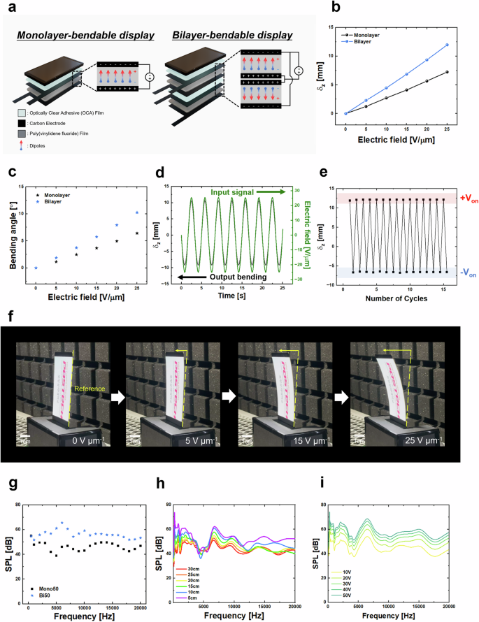
a Representation of the monolayer- and bilayer-bendable displays. b, c Comparison of the electromechanical properties of monolayer- and bilayer-bendable displays. Maximum deflection (b) and maximum angle (c) of the monolayer- and bilayer-bendable displays as a function of the applied electric field. d Time dependencies of the maximum deflection (black line) and of the applied electric field (green line) at 0.3 Hz for the bilayer-bendable display. e Cycling testing of the bilayer-bendable display operated at 25 V μm−1. f Snapshots of the deformation of the bilayer-bendable display as a function of the applied electric field. Images taken from Supplementary Video 3. g Frequency response of SPL of monolayer- and bilayer-bendable displays. h Bilayer-bendable display frequency-response curves at various measurement distances operated at 25 V μm−1. i SPL of bilayer-bendable display at different applied voltages.
As the electric field increased, the maximum bending angles of both the displays increased (Fig. 4c). When a 25 V μm−1 electric field was applied, the bilayer-bendable display exhibited a maximum bending angle of 10.24°, whereas the monolayer-bendable display showed a maximum bending angle of 6.4°, resulting in a difference of ~3.84° between the two displays. Consequently, the bilayer-bendable display induced greater deformation under the same electric field. This could be because the actuator composed of two PVDF layers generated a greater force to bend the relatively thicker and more rigid panel, resulting in a more significant deformation at the same electric field.
When a 0.3 Hz, 25 V μm−1 AC signal was applied, the bilayer-bendable display showed real-time output deflection (black line) in response to the input electrical signal (green line) (Fig. 4d). Figure 4e shows that the bilayer-bendable display operated reliably without performance degradation over 15 cycles. Regardless of whether the flexible display was laminated, as shown in Fig. 2f, g, the signal tracking and cyclic tests were well controlled. Furthermore, the bilayer-bendable display was continuously operated for 30 min, maintaining stable performance without performance degradation, as shown in Supplementary Fig. 4. Figure 4f shows gradual bending from the initial position as the electric field applied to the bilayer-bendable display varies, with the real-time operation shown in Supplementary Video 3.
To compare the changes in the electro-acoustic characteristics based on the number of PVDF layers used in the actuator, the sound pressure level (SPL) generated by applying a 50 V voltage and signals ranging from 20 Hz to 20 kHz, corresponding to the audible frequency range, to both the monolayer- and bilayer-bendable displays were measured (Fig. 4g and Supplementary Fig. 5). When the same 50 V voltage was applied to both displays, the bilayer-bendable display generated a higher SPL across the entire audible frequency range. This suggests that the bilayer-bendable display produces greater deformation when the same signal is applied, leading to a higher SPL. Figure 4h, i presents the optimal conditions for achieving the highest SPL by varying the measurement conditions of the bilayer-bendable display. Figure 4h shows that a higher SPL was produced as the distance between the microphone and bilayer-bendable display decreased. Figure 4i shows that a higher SPL is achieved when a higher voltage is applied to the bilayer-bendable display. The experimental setup for measuring the electromechanical and electro-acoustic properties of the bilayer-bendable display is shown in Supplementary Fig. 6.
Multifunctional simultaneous bending and sound emission in a bendable display through a single integrated signal
In further, we demonstrate a bendable display with multifunctionality, capable of simultaneous shape deformation and sound emission, as shown in Fig. 5. By integrating electrical signals responsible for different functions into a single signal, we enabled shape deformation and sound emission within a single display without additional components. To simultaneously achieve shape deformation and sound emission in the bilayer-bendable display, we applied a DC signal to the left and an AC signal to the right (Fig. 5a). When the DC signal is applied to the bilayer-bendable display, the display deforms according to the signal magnitude and maintains the deformed state stably. In addition, when an AC signal within the audible frequency range up to several tens kilohertz is applied, we can observe the sound pressure level (SPL) generated by the display. The DC and AC signals in Fig. 5a are combined to create the integrated signal shown in Fig. 5b, which is applied as input signal 1 to the bilayer-bendable display. Next, to achieve real-time shape deformation of the bilayer-bendable display that conveys not only simple sounds but also meaningful information, we used a low-frequency AC signal combined with a music signal (Fig. 5c). When a 0.3 Hz, 25 V μm−1 low-frequency AC signal is applied to the bilayer-bendable display, shape deformation occurs according to the signal frequency. For the music signal, Vivaldi’s “Spring, Third Movement” was used. By combining the low-frequency AC signal and music signal, an integrated signal was generated, as depicted in Fig. 5d, which was then applied as input signal 2 to the bilayer-bendable display.
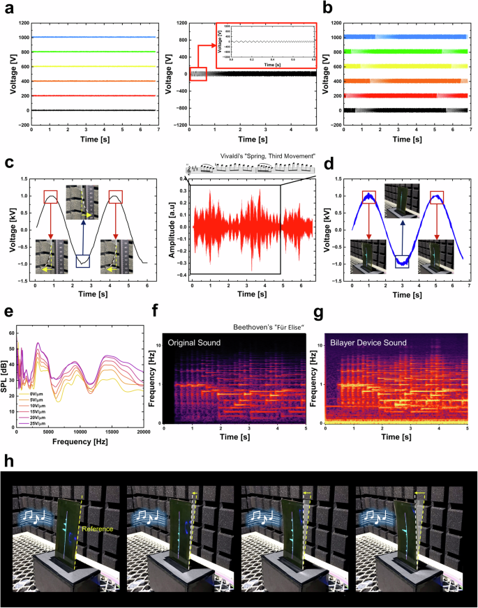
a DC and AC signals for shape deformation and sound emission. b Integrated input signal 1 (DC + AC signals). c Low-frequency AC and music signals for real-time deformation and music output. d Integrated input signal 2 (low-frequency AC + music signals). e SPL response of the bilayer-bendable display to integrated input signal 1. f, g Spectrogram results of the original sound recorded by the microphone (f) and the output sound from the bilayer-bendable display (g). h Snapshots of a bendable display with sound functionality. Images taken from Supplementary Video 5.
When input signal 1 (a combination of DC and AC signals) shown in Fig. 5b was applied to the bilayer-bendable display, the SPL generated by the display was presented in Fig. 5e. As the magnitude of the applied DC signal increased, a corresponding increase in SPL was observed, which can be due to greater bending of the display that concentrates sound energy and results in higher SPL. To verify the sound quality generated by the bilayer-bendable display, we used “Für Elise” by Beethoven as the input signal (Fig. 5f, g and Supplementary Video 4). The reliability of the sound produced by the fabricated bilayer-bendable display was confirmed by comparing the spectrogram of the original input (Fig. 5f) with the output spectrogram of the bilayer-bendable display (Fig. 5g). By applying input signal 2, which integrates a low-frequency AC signal and a music signal (Fig. 5d), to the bilayer-bendable display, we developed a multifunctional display capable of real-time dynamic shape deformation while outputting music (Fig. 5h). The real-time operation of the bilayer-bendable display is shown in Supplementary Video 5. To achieve bending, one end of the bilayer-bendable display was fixed, and upon applying input signal 2, the display bent forward and backward in response to the low-frequency AC signal, while simultaneously outputting the music signal. Consequently, we successfully demonstrated a multifunctional bendable display of practical OLED in which shape deformation and sound emission were simultaneously achieved using only a single bilayer-bendable display without any additional components by applying integrated input signal 1. Furthermore, by applying input signal 2, we designed the display to enable real-time dynamic shape deformation and the transmission of meaningful audio information through a music signal.
Discussion
To develop advanced multifunctional flexible displays, we implemented a thin, lightweight, flexible, dynamic, bendable display with sound functions, using an asymmetric deformation of hybrid actuator. By using a hybrid actuator structure composed of an active PVDF layer and an inactive section of a practical flexible display, we efficiently converted in-plane deformation into enhanced out-of-plane bending. In addition, through the positive or negative strain engineering of the PVDF used as the active part, bidirectional and complex multiform deformations via electrical signals can be achieved without the need for additional mechanical hinges. As a result, we developed a bendable display that dynamically responds to electrical signals by attaching a single PVDF actuator to a flexible OLED panel. Bending performance was further enhanced by fabricating an actuator structure with dual PVDF layers. In addition, by leveraging the rapid piezoelectric actuation of PVDF, the OLED panel vibrates as a diaphragm, achieving sound emission without requiring an additional speaker. The sound pressure level (SPL) was evaluated in the audible frequency range to characterize the electro-acoustic properties, with a high-frequency AC signal applied to the fast-responding PVDF and flexible OLED diaphragm. The spectrogram of the sound generated by a plastic-OLED display, when a music signal was applied, was comprehensively analyzed. Consequently, a multifunctional bendable display is realized that can simultaneously convey its multifunctional capabilities through both deformation and auditory information by integrating a bending-inducing signal with a music signal. This dynamically bendable display technology can be applied to various electronic devices, paving the way for innovative applications in multisensory displays, multifunctionality, and flexible electronics.
Methods
Fabrication of the hybrid actuator
A mask for electrode formation was placed on the PVDF film (KF Piezo, Kureha), and carbon spray (838AR, MG Chemicals) was spray-coated at regular intervals. After spray-coating carbon electrodes on both the top and bottom of the PVDF film, wires were attached to the electrode pads to establish electrical connections. An optically clear adhesive (OCA) film (LG Chem) was attached to top of the upper electrode, and finally, a polyimide film (PI Advanced Materials) was placed on the OCA film to fabricate the hybrid actuator. The dimensions of the hybrid actuator were 5 × 1 cm2.
Fabrication of the dynamic, bendable display
A mask for electrode formation is placed on the PVDF film, and carbon spray is spray-coated at regular intervals to form electrodes. After spray-coating carbon electrodes on both the top and bottom of the PVDF film, wires are attached to the electrode pads to establish electrical connections. An OCA film is attached to the top of the upper electrode. An OLED display panel (Shenzhen Huaizhi Technology Co., Ltd.) is then placed on the OCA film to fabricate a monolayer-bendable display. Two single actuators with the same structure, where electrodes are formed on both the top and bottom of the PVDF film, are fabricated, and an OCA film is placed between them. Then, an OCA film is attached to the upper electrode of the top single actuator. Finally, an OLED display panel is placed on the OCA film of the upper electrode to fabricate a bilayer-bendable display. The dimensions of the display were 14 × 7 cm2.
Measurement of electromechanical and electro-acoustic properties
For the electromechanical deformation of the hybrid actuator and dynamic, bendable display, a laser displacement sensor (LJ-V7200, Keyence), an arbitrary function generator (AFG1022, Tektronix), and a high-voltage amplifier (609 B, Trek) were used. The electrical signal from a high-voltage amplifier was monitored using an oscilloscope (TBS2000B, Tektronix).
To obtain the electro-acoustic properties of the dynamic, bendable display, an arbitrary function generator (AFG31021, Tektronix), a high-voltage amplifier (9400A, Tabor Electronics), and an audio amplifier (MK-300, Omnitronic) were used. The sound from the dynamic, bendable display was recorded with a commercial microphone (4966, Brüel & Kjær an HBK company).
Finite element method
The displacement magnitude of the PVDF actuator, which was deformed into multiple forms, was simulated using the COMSOL Multiphysics 5.6 software package. The polarization direction of the PVDF was set from bottom to top. The inactive layer used polyimide, with the Young’s modulus and Poisson’s ratio set at 3.1 GPa and 0.34, respectively. The thickness of PVDF and polyimide were 40 and 50 μm, and the length and width were the same as those used in experiments. The direction of the applied signal relative to the polarization was adjusted to analyze the deformation of the hybrid actuator because of strain engineering.


Responses