Energy-efficient electric control of magnetization in polymer-based magnetoelectrics for spintronic applications

Introduction
The magnetoelectric (ME) effect, discovered over a century ago, has become one of the most captivating research areas, promising transformative impacts on modern technology1,2,3. This effect—where electric and magnetic fields are coupled in a material—enables electric field control over magnetization and modulation of electric polarization via magnetic fields4. These capabilities are invaluable in microelectronics, sensors, energy harvesting, biomedical tools, and especially in spintronics (SP), where electron spin control is central to data processing and storage5,6,7,8. Strain-mediated coupling plays a critical role in ME composites, where strain generated in the ferroelectric phase is transferred to the magnetostrictive phase, modulating the magnetization of the magnetic particles. While this strain is typically generated by applying an electric field, recent studies have shown that optical excitation can also induce strain in ferroelectric materials, offering an alternative to high-voltage requirements9,10,11,12.
Multiferroic materials, which exhibit both ferroelectric and ferromagnetic properties, have emerged as frontrunners in ME research for their ability to improve functionality and energy efficiency in devices13,14. However, single-phase multiferroics typically suffer from weak ME coupling and are often limited to low-temperature applications, restricting their potential4. To address these constraints, researchers have shifted focus toward multiferroic composites, combining piezoelectric and magnetostrictive phases to achieve strong ME coupling at room temperature15. These composites provide a versatile alternative for applications ranging from high-speed memory to low-energy SP devices16.
Among multiferroic composites, polymer-based systems have garnered considerable attention due to their mechanical flexibility, ease of processing, and ability to host a wide range of functional fillers4. The combination of piezoelectric polymers like P(VDF-TrFE) or cellulose with magnetostrictive nanoparticles creates opportunities to fine-tune the material’s properties for specific applications4,17. These composites offer the potential for colossal ME responses, thanks to the large piezoelectric stress coefficients and effective stress transfer within the polymer matrix. Additionally, their compatibility with technologies such as additive manufacturing further enhances their application potential18.
While much research has been conducted on the direct ME effect (input: magnetic field; output: electric field), the converse ME effect (CME)—in which an electric field modulates magnetization—remains underexplored in polymer-based composites, particularly for SP applications19. SP devices, which rely on controlling the spin of electrons, stand to benefit immensely from the CME, as it allows for non-volatile, high-speed, and energy-efficient operation.
One of the most effective ways to evaluate the CME—where an applied electric field modulates magnetization—is to study how electrical poling affects key magnetic properties, particularly magnetic saturation and coercivity19,20. Electrical poling induces strain in the piezoelectric phase, which transfers mechanically to the magnetostrictive phase, altering its magnetic state. Changes in magnetic saturation and coercivity are direct indicators of how the magnetization process is influenced by the electric field. Observing these changes provides clear evidence of the CME’s efficiency and strength, making it a suitable method for assessing the potential of ME composites in practical applications.
This study builds on previous research on polymer-based ME composites by introducing two additional magnetostrictive fillers, Ni80Fe17Mo3 (NFM) and Ni0.5Zn0.5Fe2O4 (NZFO), alongside CoFe2O4 (CFO). These fillers possess distinct magnetostrictive coefficients and particle sizes, allowing for a systematic investigation of size-dependent ME effects and strain transfer efficiency. Unlike previous studies that primarily focused on CFO-based composites, this work explores the impact of varying magnetostrictive properties on coercivity, magnetization dynamics, and ME coupling efficiency. In particular, the study aims to assess whether microscale fillers (NZFO) enhance strain transfer efficiency due to multi-domain behavior and if nanoparticles (NZFO, CFO) exhibit notable coercivity changes upon electrical poling. By analyzing these effects, this work seeks to establish a broader framework for optimizing ME composites for SP applications, clarifying the role of particle size and magnetostriction in tailoring the ME response.
Thus, this study aims to bridge this gap by investigating the CME effect in polymer-based nanocomposites containing various magnetostrictive fillers. By examining the relationship between particle size, magnetization, coercivity, and ME coefficients, we seek to uncover how nanoparticle size influences the ME response and explore how these materials can be optimized for next-generation SP devices. To this end, five different types of magnetostrictive fillers were incorporated (Table 1):
-
i.
CoFe2O4 nanoparticles, chosen for their exceptionally high negative magnetostrictive coefficient (−220 ppm), which is the highest among ferromagnetic nanoparticles. This makes them ideal for applications requiring a strong magnetostrictive response, contributing significantly to the ME coupling in the composite system21,22;
-
ii.
Fe3O4 nanoparticles, known to be superparamagnetic with a remarkable magnetostriction of ~50 ppm23;
-
iii.
Nd2Fe14B micropowder, which has moderate magnetostriction (20 ppm) and a high magnetic energy product. Its inclusion balances the overall performance of the composite by contributing to both magnetostriction and high energy density23;
-
iv.
Ni80Fe17Mo3 permalloy nanopowder with a magnetostriction of 160 ppm24. This material provides strong magnetoelastic effects, contributing to the overall sensitivity of the composite and improving the performance in lower magnetic field conditions;
-
v.
Ni0.5Zn0.5Fe2O4 with a negative magnetostriction of −8 ppm25, adding another layer of tunability to the composite. The negative value helps balance the overall magnetostrictive response and can improve specific applications where such behavior is required, particularly in vibration or strain-sensing technologies.
These fillers were combined with Poly(vinylidene fluoride-co-trifluoroethylene) [P(VDF-TrFE)], a polymer known for its high piezoelectric coefficient (the highest among polymers), physicochemical stability, and ease of processing, including compatibility with additive manufacturing technologies. This polymer matrix provides excellent mechanical flexibility, making it ideal for flexible and wearable sensor applications, while its piezoelectric nature enhances the overall ME coupling in the composite26,27.
As illustrated in Fig. 1, in the final ME composite composed of piezoelectric P(VDF-TrFE) and magnetostrictive fillers, the electric domains are initially randomly oriented (i). Through electrical poling, the electric domains become aligned (ii), leading to changes in magnetic saturation and coercivity (iii), providing evidence of the converse ME effect.

Schematic representation of the concept proposed in the manuscript.
Results and discussion
To achieve efficient ME coupling, it is critical to properly understand the structural, thermal, mechanical, electrical, and magnetic behavior of the composites. Each of these properties plays a role in determining the effectiveness of the ME effect, particularly in terms of the efficiency of the magnetic and electric coupling.
Morphological characterization
The morphology of the composite films significantly influences the ME coupling, as it affects the dispersion and interaction of the magnetostrictive fillers within the polymer matrix. A uniform distribution is essential for efficient mechanical stress transfer, which is critical for the converse ME effect. Thus, the morphology was evaluated through SEM (Fig. 2).
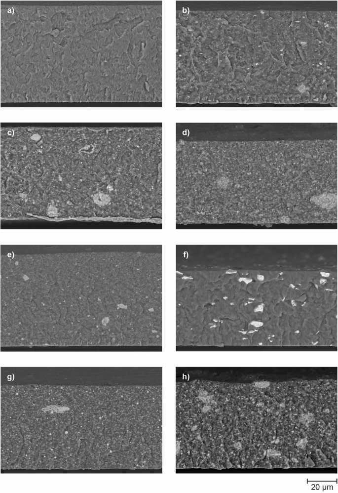
Cross-section SEM images of a neat P(VDF-TrFE) film and b CFO5, c CFO10, d CFO20, e FO20, f NdFeB20, g NFM20 and h NZFO20 composites.
The cross-sectional SEM images (Fig. 2) show a compact morphology for all samples, with clear differences between neat P(VDF-TrFE) (Fig. 2a) film and the distinct composites (Fig. 2a–h). While the neat polymer film exhibited a smooth and homogenous surface, the composite films showed varying degrees of particle dispersion based on filler type and concentration.
The cryogenic fracture of the samples revealed a brittle surface typical of the laminates after breakage. For the nanoparticle composites, images (Fig. 2b–h) show well-dispersed particles across the surface, with noticeable agglomerations in CFO10, CFO20, and NZFO20. On the other hand, NdFeB20 composites exhibited a more uniform distribution of NdFeB microparticles (Fig. 2f). The observed uniform distribution of Nd2Fe14B microparticles compared to the tendency of CFO nanoparticles to agglomerate can be attributed to differences in particle size and surface energy. Nd2Fe14B microparticles, with their larger size (micrometer scale), exhibit weaker van der Waals interactions compared to CFO nanoparticles, which are in the nanometer range and have a significantly higher surface-to-volume ratio. This higher surface energy of CFO nanoparticles promotes aggregation, particularly during the dispersion process. Additionally, the larger size of Nd2Fe14B particles reduces their mobility within the polymer matrix, facilitating a more even spatial distribution. Unlike CFO nanoparticles, which exhibit extensive interfacial bonding with the polymer matrix due to their high surface energy, Nd2Fe14B particles interact primarily through physical entrapment, further supporting their uniform dispersion. These distinctions underline the critical role of particle size and surface characteristics in achieving homogeneous composites.
As the concentration of CFO increased, larger and more frequent agglomerations were observed, especially in CFO20 composites. This agglomeration is effectively observed in nanoparticle systems (Fig. 2b, c, d, e, g, h) than in microparticle systems (Fig. 2f), due to high surface energy leading to mutual particle attraction28. Electrical poling had no influence on the composite’s morphology.
Thermal characterization
The thermal stability and crystallinity of the composites (Fig. 3a and Table 2) are directly related to their ability to maintain structural integrity under operational conditions. High crystallinity and proper thermal transitions ensure that the material can sustain the mechanical strains necessary for ME coupling.
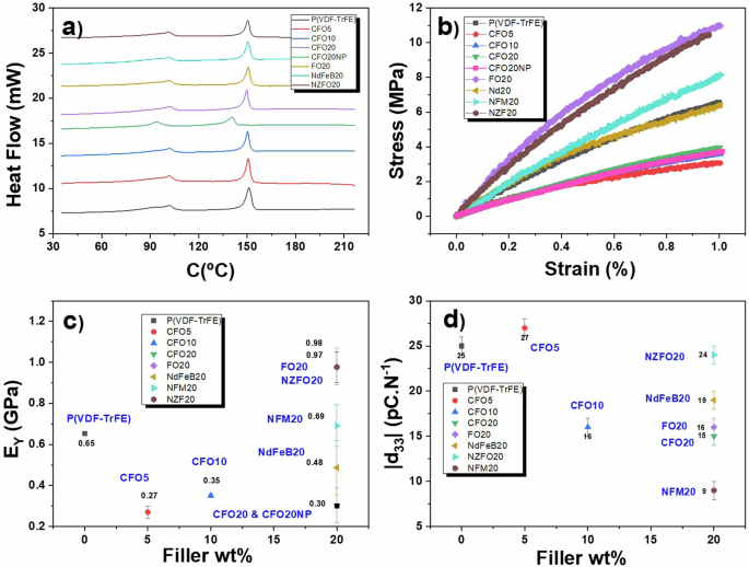
a DSC thermogram (heating) for the neat polymer and composites, b Stress-strain plots for the neat polymer and composites, c Young’s modulus obtained from (b) as a function of the filler type and content; and d |d33| piezoelectric constant as a function of filler type and content. The error bars in (c) and (d) represent the standard deviation.
The results revealed that the thermal stability of the composites remained largely unaffected by the inclusion of magnetic fillers. All samples exhibited a Tc at ≈102 °C (smaller peak on the graph) and a Tm ≈ 150 °C. Crystallinity, however, was found to be sensitive to filler content. While composites with up to 10 wt% CFO nanoparticles showed no significant change in crystallinity compared to the neat polymer (24%), increasing the particle content to 20 wt% caused a notable reduction in crystallinity, ranging from 15.7% in NFM20 to 22.5% in NdFeB20. This reduction is consistent with the behavior of magnetic particles, which initially act as nucleating agents, leading to the formation of smaller and more disordered spherulites29,30, but for larger filer concentrations act defects due to the physical constrains imposed to the crystallizing polymer. By comparing the CFO20 and CFO20NP thermal characteristics it was found that the electrical poling increased Tc, Tm, ({Delta H}_{{{{rm{f}}}}}), and ({{{{rm{chi }}}}}_{{{{rm{c}}}}}). Such poling aligns the dipoles in P(VDF-TrFE), promoting better ordering of the polymer chains. This alignment helps the material crystallize more effectively, leading to an increase in crystallinity29,30. As crystallinity increases, thermal properties such as Tc and Tm, ({Delta H}_{{{{rm{f}}}}}) also rise because more energy is required to break down the well-ordered crystalline regions during heating31,32.
Mechanical properties
The mechanical properties, specifically Young’s modulus (E) and tensile strength are critical for effective ME coupling. These properties determine the material’s ability to transfer strain between the piezoelectric and magnetostrictive phases. (Fig. 3b, c).
The stress-strain curves (Fig. 3b) revealed a predominantly elastic deformation of all films up to 0.1 strain. Notably, the FO20 and NZFO20 films demonstrate the highest load-baring capability at this strain value, followed by NFO20, neat P(VDF-TrFE) film, Nd20, and finally, CFO20, 10 and 5 composites. The Young’s modulus of each sample was determined at the linear stage of the curve using Eq. 2. The inclusion of CFO nanoparticles (regardless of their wt%) and NdFeB microparticles led to a reduction in EY (0.27–0.48 GPa) compared to P (VDF-TrFE) film (0.65 GPa). Conversely, the reinforcement with 20 wt% of FO and NZFO fillers demonstrated a significant enhancement of the EY of the nanocomposite films to ~0.98 GPa, while NFM particles only marginally improved Young’s modulus compared with neat P(VDF-TrFE), exhibiting a 0.69 GPa value. The poor homogeneity and large agglomerations of CFO nanoparticles, as well as the size of microparticles of NdFeB composites, allow to explain their slightly humble mechanical performance. Nevertheless, all films exhibited Young’s modulus values in the same order of magnitude of the ones previously reported on polymer-based composites with high ME coupling33. The negligible change in Young’s modulus of the polymer-based ME composites after electric poling is primarily attributed to the intrinsic flexibility and low stiffness of the P(VDF-TrFE) matrix. Unlike ceramic-based ME composites, which exhibit significant changes in mechanical properties due to stress redistribution from dipole alignment, the polymer matrix distributes strain uniformly without introducing considerable structural modifications. Additionally, the relatively low filler content (20 wt%) and the uniform dispersion of magnetostrictive particles ensure that the strain transfer between the piezoelectric and magnetostrictive phases does not significantly alter the bulk mechanical stiffness. Such balance between stiffness and flexibility is essential for an optimized ME response23. Electrical poling had no significant influence on the composite’s mechanical properties.
Piezoelectric, electric, and dielectric properties
The modulus of the piezoelectric coefficient |d33|(it is negative for PVDF-based materials) of the different composites is presented in Fig. 3d. The measurements were carried out 2 days after poling to minimize the electric charges accumulated throughout the polarization process. Results revealed a similar piezoelectric constant between neat P(VDF-TrFE) and CFO5 films (25–27 pCN−1), corresponding to the higher values among all composites, while NFM20 presented the lower |d33| value of 6 pC.N−1. All the other composites exhibited intermediate |d33| values between 15 and 19 pC.N−1. The observed decreased piezoelectric response of composites with particles contents higher than 5 wt% is caused by a disruption of the connectivity of the piezoelectric matrix and interfacial charge and mechanical defects. The low crystallinity of the NFM20 sample also explains its lower piezoelectric response33,34.
Electrical conductivity and dielectric behavior (Fig. 4) understanding are fundamental for ensuring effective electrical polarization under applied magnetic fields. In particular, proper dielectric constant values are necessary to facilitate the converse ME effect, in which an electric field induces magnetization changes.

a Electric current as a function of applied voltage for the different samples. b Electric conductivity values for each sample. The specific conductivity values are given within the graphic, where the error bars representing the standard deviation. c Real part of the dielectric response and d tanδ as a function of frequency for P(VDF-TrFE)-based composites with different filler types and content.
The current-voltage (IV) curves (Fig. 4a) demonstrate that all films displayed Ohmic behavior, with a linear increase in current as the voltage increased. Notably, the inclusion of 20% of NFM, CFO, and NZFO magnetic particles led to an increase in DC surface conductivity, reaching values between 8.3 × 10⁻7 and 5.3 × 10⁻⁶ S.m−1, compared to 6.6 × 10⁻⁸ S.m−1 for neat P(VDF-TrFE). Despite this increase, none of the composites achieved conductivities below 10−3 S.m−3, being all suitable for a robust ME effect23.
In terms of dielectric properties (Fig. 4c, d), the real part of dielectric permittivity (ε’) of all samples decreased with increasing frequency due to dipole relaxation at the crystalline/amorphous and polymer filler interfaces33. Additionally, ε’ and dielectric losses (tanδ) increase with the inclusion of magnetic particles. On the one hand, the inclusion of magnetic particles increases the polarization at the interface between them and the P(VDF-TrFE), leading to a higher dielectric constant through contributions from the larger dielectric constant of the filler with respect to the matrix and to Maxwell-Wagner-Sillars contributions33. On the other hand, they also increase the electrical conductivity resulting in higher dielectric losses30,35. Nonetheless, all films maintained tanδ values below 0.2, an essential criterion for effective ME coupling23. The improvement in dielectric properties and the stability of low dielectric losses after electrical poling in the composites can be attributed to several key factors related to the alignment of dipoles, crystallinity, and the interaction between the polymer matrix and magnetic fillers35. The improved dipole alignment can suppress charge carrier motion and minimize relaxation processes, which maintains low dielectric losses. Additionally, poling allows to stabilize the interface between the polymer and the magnetic nanoparticles, ensuring that the nanoparticles contribute positively to the dielectric properties without introducing excessive energy dissipation36. The increase in polarization at the ferromagnet/piezoelectric interface in polymer-based ME composites upon adding magnetic particles is primarily driven by strain-mediated coupling at the interface. When an electric field is applied, the piezoelectric polymer matrix, such as P(VDF-TrFE), generates strain due to its piezoelectric nature, which is transferred to the magnetostrictive particles. This strain induces localized mechanical stress on the particles, altering their magnetic state and, in turn, creating feedback that enhances dipole alignment in the piezoelectric phase near the interface. Additionally, the introduction of magnetic particles increases the interfacial area and leads to charge accumulation and strain concentration, resulting in a more pronounced polarization near the interface. These interactions highlight the synergistic role of the magnetostrictive fillers and piezoelectric matrix in improving the overall ME coupling of the composite.
Magnetic and ME properties
To access the ME properties of the composites room-temperature hysteresis cycles have been evaluated as a function of the poling state (Fig. 5).

Room-temperature hysteresis cycles for: a CFO5 and CFO5NP; b CFO10 and CFO10NP; c CFO20 and CFO20NP; d FO20 and FO20NP; e NFM20 and NFM20NP; f NdFeB20; and NdFeB20NP; and g NZF020 and NZFO20NP. h Variation of the magnetization (ΔMS) as a function of the CFO wt%, where the error bars representing the standard deviation.
By increasing the CFO content from 5 to 20 wt% (Fig. 5a–c), the magnetization saturation (ΔMS) value also increased. By keeping the same particle wt% and changing the particle type (Fig. 5d–h) more substantial changes in the MS value are found in the CFO20 and NFM20 composites and a more moderated difference was observed in the NFO composites. The NZFO sample shows a different magnetic behavior: despite exhibiting the lower variation in the MS value, the magnetization exhibited an easier route when the composite was poled. Interestingly, in the composite with smaller magnetostrictive nanoparticles (NZFO), electrical poling not only changed the magnetization saturation but also facilitated the magnetization process, causing a shift from hard-axis to easy-axis magnetization37. This behavior is unique compared to larger particles. Smaller nanoparticles are characterized by a higher surface-to-volume ratio compared to larger ones leading to enhanced surface effects. As a result, the strain induced by electric poling might have a more profound effect on the smaller nanoparticles making it easier for the magnetization to switch from a hard axis to an easy axis. Additionally, smaller nanoparticles generally exhibit weaker intrinsic magnetic anisotropy compared to larger particles37. This weaker anisotropy makes them more susceptible to external influences, such as strain from the piezoelectric polymer. The electric poling leads to dipole orientation and increase of the strain of the matrix that is transferred to the magnetic particles, reducing magnetic anisotropy energy barriers, facilitating magnetization along the easy axis, which is not as pronounced in larger particles with stronger inherent anisotropies. In the same way, in smaller particles, the strain transfer from the P(VDF-TrFE) polymer might be more uniform and effective. This uniform strain within the composite could reduce the energy required to switch the magnetization direction, easing the transition from hard-axis to easy-axis magnetization. Finally, some of the nanoparticles in the size range of 10–30 nm might also exhibit superparamagnetic-like behavior at room temperature38,39. In this state, the magnetic moments of the nanoparticles can fluctuate more easily, and electric poling could help align these moments more effectively by reducing energy barriers, and facilitating the magnetization along the easy axis.
In the case of the CFO-based composites (Fig. 5h) the ΔMS increases almost linearly with the wt%, from 1% to 11%. This increase is attributed to the increase of the magnetic phase within the ME composite. A further increase in the CFO wt% may decrease the ΔMS value due to the agglomeration of the particles33. For the same filler content, ΔMS is also directly proportional to the magnetostrictive coefficient (Fig. 6a). The increase in saturation magnetization with higher CFO wt% reflects the greater contribution of the magnetic phase, which enhances the ME coupling through more efficient strain transfer between the piezoelectric matrix and the magnetostrictive fillers. While samples with lower CFO content (e.g., CFO5 or CFO10) may require less energy to manipulate magnetization due to their reduced saturation levels, higher CFO content (e.g., CFO20) enables a stronger ME response, as evidenced by the higher α’33 values observed. This trade-off underscores the need to optimize the composite’s composition based on the energy-efficiency requirements and functional demands of the intended SP application.
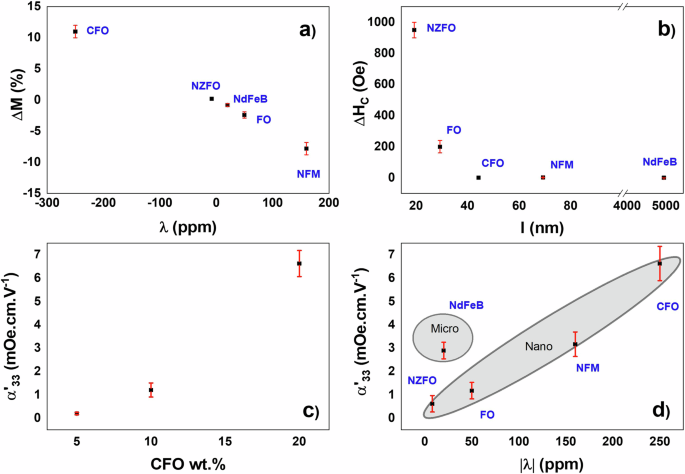
a Variation of the saturation magnetization (ΔMS) as a function of the magnetostrictive coefficient (λ) of the fillers on the composite with 20 wt% of magnetic particles. b Variation of the coercitivity (ΔHC) as a function of the size (l) of the fillers on the composite with 20 wt% of magnetic particles. ME coefficient (α’33) as a function of the: c CFO wt%; and d magnetostrictive coefficient (λ) of the fillers on the composite with 20 wt% of magnetic particles. The error bars represent the standard deviation.
CFO and ZFO possess a negative magnetostrictive coefficient, meaning that their magnetization decreases in the direction of applied magnetic field. Similarly, P(VDF-TrFE) exhibits a negative piezoelectric coefficient, indicating that its polarization decreases in the direction of the applied field7. When these materials are combined in the same composite, the application of a positive electric field during the poling procedure causes P(VDF-TrFE) to contract in the direction of the applied field, thereby transmitting a compressive force to the magnetic particles. This compressive force results in an increase in magnetization in the direction of the applied electric field. In contrast, particles with a positive magnetostrictive coefficient will respond oppositely, leading to the opposite behavior40. This difference explains the sensitivity to positive and negative magnetostrictive coefficients observed in Fig. 6a.
The variation in coercivity with particle size (Fig. 6b) is strongly tied to the size-dependent magnetic behavior of the fillers. Composites with smaller particles (NZFO20) experience increased coercivity after poling due to enhanced surface effects, stronger strain-induced anisotropy, and single-domain behavior, which makes magnetization reversal harder. This increase in coercivity helps explain why electrical poling has a greater effect in facilitating the magnetization process in smaller particles observed in Fig. 5g. For larger particles, the almost logarithmic relationship reflects a transition to more core-dominated, multi-domain behavior, which reduces both coercivity and the influence of electrical poling on the magnetization process. From the data presented in Fig. 5, it was obtained the converse ME coefficient α´ of 6.5 mV.cm−1.Oe−1 for CFO20 (Fig. 6c), and 0.62, 2.04, 1.22, and 3.21, for NZFO20; NdFeB20; FO20; and NFM20, respectively.
Composites with nanosized particles (NFM20; NdFeB20; FO20; and CFO20) exhibit lower weighted ME response (α’/wt%) when compared to composites with microsized particles (NZFO20) (Fig. 6c) as a result of the less efficient strain transfer due to imperfections in particle-matrix coupling, surface defects, or agglomeration effects (Fig. 2). Additionally on the micrometer range, particles are more likely to exhibit multi-domain magnetic behavior. In this case, the domain walls can move more easily in response to the mechanical strain induced by electrical poling, contributing to a stronger magnetostrictive response. This multi-domain structure allows for more effective reorientation of the magnetization under strain, which enhances the ME coefficient.
This effect is particularly evident in composites where the filler’s electrical properties interact strongly with the ferroelectric matrix under polarization. For the reported samples, significant changes in saturation magnetization were observed for most composites, particularly CFO-based ones, which possess high magnetostrictive coefficients. Conversely, for NZFO and FO samples, the lack of significant variation in coercivity suggests that smaller magnetostrictive coefficients and nanoparticle sizes result in reduced stress transfer effects. Thus, these findings highlight the critical role of the electrical polarization of the matrix in enhancing magnetization dynamics, further supporting the potential of polymer-based ME composites for energy-efficient device applications. Notably, for SPs, the converse ME coupling demonstrated in this work generates magnetic fields of up to 32 Oe (Table 3). This field strength is two orders of magnitude greater than the switching field required to manipulate the spin of the free layer in certain SP devices recently reported23,41,42,43,44, presenting promising potential for high-performance SP device applications.
In this way, the observed CME effect in the studied polymer-based composites, reaching up to 32 Oe, is particularly relevant for SP applications where small variations in magnetization can influence anisotropy fields and domain wall motion, rather than requiring full saturation magnetization. While the remanent magnetization remains relatively stable, the strain-mediated tuning of magnetization can still play a critical role in SP devices with low-energy switching mechanisms, such as magnetic tunnel junctions and spin-orbit torque systems, where switching fields as low as a few Oe have been reported. Furthermore, the response of the ME coupling coefficient to opposite voltage polarities remains an open question in this study. Future work will explore whether the magnetization response exhibits non-volatile behavior, hysteresis effects, or a strictly linear dependence on the applied electric field. This will be essential to fully evaluate the potential of these composites for memory and logic applications. These aspects will be further investigated to refine the understanding of voltage-controlled magnetization in polymer-based MEs.
Conclusions
This study demonstrates the significant impact of particle size and magnetostrictive properties on the ME behavior of polymer-based nanocomposites, revealing key insights for optimizing ME materials for advanced SP applications. Particle size and magnetostriction were found to directly influence magnetization changes and the converse ME coefficient (α’), with larger particles like NdFeB microscale fillers exhibiting a stronger weighted ME response (α’/wt%) due to enhanced strain transfer and multi-domain magnetic behavior. In contrast, CoFe2O4-based composites achieved the highest ME coefficient (up to 6.5 mV·cm−1·Oe−1) due to the material’s high magnetostriction. Smaller particles (10–30 nm) yielded lower ME coefficients but exhibited a unique behavior: electrical poling enhanced magnetization by shifting it from hard-axis to easy-axis orientation.
From a practical standpoint, particularly for SP devices, the converse ME coupling observed in these composites generates magnetic fields up to 32 Oe—two orders of magnitude greater than the switching field needed for free-layer spin manipulation in certain SP devices. This notable increase underscores these materials’ potential for high-performance SP device applications. Moreover, size-dependent coercivity trends observed in the composites highlight the tunability of magnetic properties through nanoparticle size: smaller particles exhibited higher coercivity due to enhanced surface effects.
Overall, the findings provide a pathway for tailoring ME composites via particle size and magnetostrictive properties, enhancing their suitability for next-generation, energy-efficient SP devices with improved tunability and performance.
Methods
Materials
The base matrix for the nanocomposites, P(VDF-TrFE), was supplied by Piezotech and is composed of 70 mol% vinylidene fluoride and 30 mol% trifluoroethylene. The solvent used to dissolve the polymer was dimethylformamide (DMF) from Merck.
The magnetic fillers incorporated into the composite films included CoFe2O4 nanoparticles (35–50 nm), Fe3O4 nanoparticles (30 nm), Nd2Fe14B micropowder (≈5 µm), Ni0.5Zn0.5Fe2O4 nanoparticles (10–30 nm), and Ni80Fe17Mo3 nanopowder (70 nm), all sourced from Nanostructured & Amorphous Materials Inc. (USA) except for the Nd2Fe14B micropowder, which was obtained from Magnequench GmbH (Germany).
Composite fabrication
Composite films were fabricated by dispersing magnetostrictive fillers into 10 mL of DMF via ultrasonic treatment for 5 h, followed by mechanical stirring for 1 h with P(VDF-TrFE) powder to achieve uniform dispersion. Each ME composite contained 20 wt% magnetostrictive filler and 80 wt% P(VDF-TrFE). To study the influence of the magnetostrictive nanoparticle content, composites with three distinct weight percentages (5, 10, and 20) of CoFe2O4 were also produced.
The resulting mixture was then coated by doctor-blade onto clean glass substrates, with film thickness controlled between 45 and 60 µm. After solvent evaporation, the films were melted at 215 °C for 10 min and then cooled at room temperature. Once removed, the films exhibited a compact morphology and smooth, flexible, and homogeneous surfaces.
Nomenclature of ME composite films
The following nomenclature (Table 4) will be used throughout the manuscript:
Characterization of ME composite films
The cross-sectional morphology and particle dispersion of the ME composites were examined using a Nova NanoSEM 200 scanning electron microscope (SEM). Before analysis, each film sample was immersed in liquid nitrogen for 1 min and then cryogenically fractured to create a clean fracture surface. This surface was coated with a thin layer of gold-palladium previous to the SEM measurements.
Differential scanning calorimetry (DSC) was used to thermally characterize the produced ME composites. Measurements were performed using a DSC 6000 PerkinElmer instrument, with a temperature range from 30 to 220 °C, a heating rate of 10 °C.min−1, and a nitrogen flow of 20 ml.min−1. The films’ crystallinity (χc) was determined from the melting enthalpy (∆Hf) using the following Eq. 1:
where ({Delta H}_{{{{rm{f}}}}}^{* }) (91.45 J.g−145) is the melting enthalpy of P(VDF-TrFE) with a crystallinity of 100%, and m its weight fraction in the composite.
The mechanical properties of the ME films were evaluated at room temperature under tensile loading conditions, using a deformation speed rate of 0.5 mm.min−1 in an Autograph AG-IS (Shimadzu) testing machine equipped with a 500 N load cell. The Young’s modulus (E) of the films was determined from the elastic linear region (up to 0.1% strain) of the stress-strain plots, using the Eq. 2:
where σ is the stress and ε is the strain.
The DC volume electrical conductivity of the films was obtained by assessing the room-temperature characteristic I/V curves with a Keithley 6487 picoammeter and voltage source. The electrical resistivity (ρ) was calculated with Eq. 3:
where R is the resistance obtained from the slope of the I/V curve, w, and l are the width and length of the electrodes, respectively, and t is the thickness of the film measured by a Digimatic Micrometer MDC-25PX. The characteristic surface DC conductivity (σDC) of each sample was then determined as the inverse of the resistivity:
The films’ capacitance (C) and dielectric losses (tanδ) were measured using a QuadTech 1920 instrument, applying 0.5 V over a frequency range from 1 Hz to 1 × 10⁶ Hz at room temperature. Before measurement, circular electrodes with a 5 mm diameter were deposited on both sides of each film. The real part of the dielectric permittivity (ε’) was calculated using the Eq. 5:
where ε’ is the dielectric permittivity, C is the capacitance, t is the film thickness, ε₀ is the vacuum permittivity constant (8.85 × 10⁻12 F.m−1), and A is the electrode area.
The piezoelectric coefficient (d33) of the films was obtained at room temperature using a model 8000 d33 meter from APC Int. Ltd. Before measurement, each film was poled in a homemade corona chamber. The sample was placed ~2 cm from the corona grid and exposed to a 15 kV voltage at 120 °C for 1 h. The cooling phase was conducted at room temperature while maintaining the same electric conditions.
The magnetic properties of the ME films were measured at room temperature using a vibrating sample magnetometer from Microsense 2.2, in the magnetic field range of −18,000 to 18,000 Oe.
The transverse ME coupling coefficient (({alpha }_{33}^{{prime} })) was determined using the formula reported in23 and by converting cgs and SI units46 (Eq. 6).
where (varDelta B) is the induced magnetic field; (varDelta E) the poling electric field; (varDelta M) the variation of the magnetic saturation between poled and non-poled samples; (rho {_c}) the density of the composite; (t) the poling distance and V is the applied voltage.


Responses