Enhanced exchange bias in all-oxide heterostructures with cation-ordered ferrimagnetic double-perovskite

Introduction
The exchange bias (EB), typically arising from the interfacial magnetic couplings between ferromagnetic (FM) and antiferromagnetic (AFM) layers, plays a vital role in spintronic applications such as spin valves and magnetic tunneling junctions1,2,3,4,5. Among various material systems, the all-oxide heterostructures have attracted huge research interests, due to the capability to engineer interface at the atomic scale and the potentials to realize electric-field controlled magnetism for next-generation energy-efficient spintronic devices6,7,8,9,10. To date, research efforts have been mostly devoted to bilayers of FM oxides such as La0.7Sr0.3MnO3 (LSMO) and G-type antiferromagnetic/multiferroic oxides such as LaFeO3 (LFO) or BiFeO3 (BFO) with high Curie and Néel temperatures11,12. The reversible electric-field control of EB has been successfully demonstrated in all-oxide heterostructures such as LSMO-BFO13,14,15. However, the block temperature (TB), above which the EB effect vanishes, remains relatively low (usually below 100 K) in these FM-AFM oxide heterostructures, although several approaches such as engineering carrier concentration and interfacial polarity have been attempted15,16,17. Efficient strategies to enhance the EB in all-oxide heterostructures, essential for promoting the applications, have yet remained elusive.
Double-perovskite oxides A2BB’O6, with rock-salt-like ordering of B-site cations and ferrimagnetic (FiM) spin structure, provide an alternative route to address the above challenge. Figure 1a schematically compares the interfacial magnetic coupling of (001)-oriented heterostructures comprised of G-type AFM perovskite with FM perovskite (left panel) and FiM double-perovskite (right panel). Note that the G-type AFM ordering is magnetically compensated in the (001) plane. Therefore, at the FM-AFM interfaces, the interfacial magnetic coupling is likely to be mediated via spin-flop coupling, in which the coupling strength is relatively low and can be easily disturbed by thermal fluctuations18,19,20,21. On the other hand, in double-perovskite A2BB’O6 with B-site cation ordering, the spins of B and B’ cations are antiferromagnetically coupled, leading to the FiM structure with both high Curie temperatures and finite magnetization22,23,24,25,26. When interfaced with G-type AFM, it appears that adopting collinear coupling is energetically favorable and could potentially contribute to an enhanced interfacial coupling strength, offering a viable approach to improve TB and HEB. So far, this design strategy has not yet been demonstrated, likely due to the extreme difficulties in synthesizing high quality oxide heterostructures with highly ordered double-perovskites and atomically sharp interfaces27,28,29.

a Schematic diagram of interfacial spin coupling of heterostructures comprised of a G-type antiferromagnetic perovskite with a ferromagnetic perovskite (left) and a ferrimagnetic double-perovskite (right). b Schematic of crystal structure of SFRO-LFO heterostructure. c XRD θ-2θ scans for SFRO (004) peak of SFRO-LFO heterostructures with SFRO at different thicknesses. d Reciprocal space mapping (RSM) around (103) STO reflections for an SFRO-LFO heterostructure. e Off-axis XRD θ–2θ scans at (psi) = 54.7° for SFRO (111) peak of the heterostructures in c. f HADDF-STEM image at the interface of an SFRO-LFO heterostructure. The green diamonds highlight ordered Re ions.
In this study, we have successfully demonstrated an enhanced EB in the model heterostructures comprised of LFO and double-perovskite Sr2FeReO6 (SFRO), as schematically shown in Fig. 1b. The orthorhombic perovskite LFO shows collinear G-type AFM structure with Néel temperature (TN) around 740 K30,31,32. The FiM properties of SFRO strongly depend on its B-site order parameter. In SFRO with highly ordered B-site cations, high Curie temperatures of Tc ~ 400 K and saturation magnetization of MS ~ 2 ({mu }_{B})/f.u. have been reported33,34. By optimizing the growth conditions, we synthesized high-quality LFO-SFRO heterostructures with both sharp interfaces and excellent B-site cation ordering. An enhanced EB is observed with TB around 250 K and HEB up to 120 mT, which are largely increased as compared to the typical FM-AFM oxide heterostructures as exemplified by the LFO-LSMO. The SFRO thickness dependence of HEB confirms that the enhanced EB is mainly attributed to the FiM-AFM interfaces, further supported by X-ray absorption spectra (XAS) and X-ray magnetic circular dichroism (XMCD) measurements. Moreover, our modeling analysis and further experimental data suggest that the B-site cation ordering in SFRO could play an important role in enhancing the interfacial magnetic coupling strength in the heterostructures. This interface design strategy presents a new approach to developing all-oxide heterostructures for spintronic applications.
Results
Structure of SFRO-LFO with B-site ordering
High-quality SFRO films and SFRO-LFO heterostructures were grown on (001) SrTiO3 (STO) substrates using pulsed laser deposition (PLD) (see METHOD). As for the heterostructures, a 50 nm thick LFO was first deposited on STO, followed by the deposition of t nm SFRO (t = 10, 20, 30, 50). Figure 1c displays the X-ray diffraction (XRD) θ-2θ spectra of the heterostructures, showing the Bragg peak around 45.5° associated with both LFO and SFRO with similar pseudo-cubic lattice constants. As compared to the single-layer SFRO films (see Fig. S1), the Bragg peaks of the heterostructures in Fig. 1c shift to the higher angle, suggesting that the in-plane compressive strain is partially relaxed in the heterostructures. This is further supported by the reciprocal space mapping (RSM) around (103) peak as shown in Fig. 1d, showing a broad peak associated with the heterostructure due to strain relaxation. In a fully ordered SFRO with the checkerboard type, the Fe and Re cations are alternatively stacked along the [111] direction as schematically shown in Fig. 1b. Therefore, the cation ordering can be revealed by the XRD off-axis scans at (psi) = 54.7° near the SFRO (111) peak. As shown in Fig. 1e, the (111) peaks are observable in all heterostructures with different SFRO thicknesses down to 10 nm. Moreover, the peak intensity, when normalized by the (004) Bragg peak of SFRO single-layers, remains almost the same, suggesting a robust B-site cation ordering in all heterostructures (see Fig. S1).
To further characterize the cation ordering at the interface, we employed scanning transmission electron microscopy (STEM) to image the atomic structure along the <110> zone axis. As shown in Fig. 1b, the two B-site cations are ordered along this projected direction, and thereby can be resolved by high-angle annular dark field (HAADF) imaging due to different atomic number of Fe (Z = 26) and Re (Z = 75). Figure 1f shows the HAADF image of a representative SFRO-LFO heterostructure (more structural details shown in Fig. S2). The ordering of Re cations (bright contrast) is highlighted by the green diamonds, consistent with the checkerboard structure. The results demonstrate that a high degree of B-site cation ordering is realized at the interface, laying the foundation to explore the interface-induced EB.
Emergence of exchange bias in SFRO-LFO
The EB effects were examined by measuring the M-H hysteresis loops after field-cooling using the superconducting quantum interference device (SQUID). All heterostructures were first set to 400 K, which is above the TC of SFRO ( ~ 370 K), and then cooled down to 10 K with applied magnetic fields. Figure 2a shows the M-H hysteresis loops of SFRO-LFO with 20 nm thick SFRO, after a field-cooling of +5 T (red) and -5 T (blue). For positive cooling-field, the M-H loop exhibits a shift towards the negative field direction, similar to previous reports on LSMO-LFO and LSMO-BFO11,12. A vertical shift of M-H loop is also observed in SFRO-LFO, likely attributed to the strongly pinned moments that can drag the magnetic switching35,36,37,38. Note that the opposite cooling-field leads to opposite shift of M-H loops, further verifying the emergence of EB. The magnitude of EB field (HEB) for this sample is estimated to be around 58 mT at 10 K by using ({{rm{H}}}_{{rm{EB}}}=left({{rm{H}}}_{+}+{{rm{H}}}_{-}right)/2), whereas H+ and H- correspond to the positive and negative coercivity fields of the M-H loops.
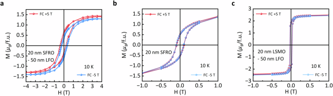
Magnetic hysteresis loops of a SFRO-LFO heterostructure with 20 nm SFRO, b 20 nm SFRO single-layer film and c LSMO-LFO heterostructure with 20 nm LSMO. All hysteresis loops were measured along the in-plane direction at 10 K after magnetic field cooling (FC). The red (blue) line represents the hysteresis loop with +5 T (-5 T) cooling field from 400 K to 10 K.
By contrast, no EB effect is observed in the 20 nm thick SFRO single-layer as shown in Fig. 2b, suggesting the EB does not arise from possible phase separations in SFRO. We also find that the coercivity fields of SFRO-LFO are largely increased as compared to the single-layer references, suggesting a strong interfacial magnetic coupling. Furthermore, we studied the heterostructures comprised of 50 nm LFO and ferromagnetic LSMO as references. As shown in Fig. 2c, the EB effect is almost negligible in the LSMO-LFO with 20 nm LSMO. As the LSMO thickness reduces to 5 nm, the EB becomes observable with a smaller HEB around 10 mT at 10 K (see Fig. S3), consistent with previous reports11,21. These results reveal the emergence of an enhanced EB in the SFRO-LFO heterostructures.
Thickness dependence of exchange bias: an interface-driven effect
To explore the role of the FiM-AFM interfaces, we further carried out systematic studies on SFRO-LFO heterostructures with different SFRO thicknesses. Figure 3a shows the temperature dependence of magnetization with a test field of 0.2 T for all heterostructures, revealing that TC is around 350 K and slightly decreases as SFRO thickness reduces. Moreover, all heterostructures exhibit saturation magnetization (MS) around 1.5 ({mu }_{B}) per chemical formula (see Fig. S4), as summarized in Fig. 3b. We note that a slight reduction of TC and MS is observed when compared to the single-layer SFRO films (see Fig. S1), probably due to the strain relaxation and B-site disorders at the interfaces.
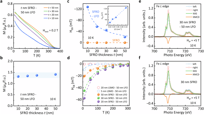
a Temperature dependence of magnetization of the SFRO-LFO heterostructures with different SFRO thicknesses, measured at 0.2 T during the warming process after field-cooling. b SFRO thickness dependence of saturation moment Ms of the SFRO-LFO heterostructures. c SFRO thickness dependence of HEB of SFRO-LFO heterostructures (blue) and single-layer SFRO films (orange). The insert image shows the fitting of ({{rm{H}}}_{{rm{EB}}}) with (1/t). No exchange bias was observed in SFRO single layers. d Temperature dependence of exchange bias field HEB of SFRO-LFO heterostructures (solid circles) and LSMO-LFO heterostructures (hollow circles). The dash lines are the fitted exponential decay. e and f show the Fe L-edge XAS and XMCD spectra of SFRO-LFO heterostructure and SFRO single-layer film, respectively, measured at 10 K and field of +5 T. The incident light is at an angle of 30 degree to the surface of the samples.
Figure 3c shows the SFRO thickness dependence of HEB at 10 K. For SFRO-LFO with 10 nm SFRO, the magnitude of HEB is up to 120 mT (see Fig. S4), significantly higher than reported values in typical FM-AFM oxide heterostructures11,12,21. The HEB decreases as SFRO thickness increases, but still remains observable even when the SFRO thickness increases up to 50 nm. The linear correlation between HEB and the inverse of SFRO thickness (1/t), as shown in Fig. 3c inset, further supports that the EB is mainly an interface effect. Figure 3d compares the temperature dependence of HEB for the SFRO-LFO and LSMO-LFO heterostructures. For all SFRO-LFO heterostructures (solid circles), the decay of HEB is relatively slow and observable EB sustains as the temperature increases up to 250 K (TB ~ 250 K). By contrast, HEB quickly decreases to zero below 100 K for the LSMO-LFO (hollow circles), consistent with previous reports11,15. The temperature dependence of HEB can be fitted by ({{rm{H}}}_{{rm{EB}}}={{rm{H}}}_{{rm{EB}}}^{0}exp (-{rm{kT}}/{{rm{E}}}^{* })) (dash lines in Fig. 3d)39,40, with the fitted ({{rm{H}}}_{{rm{EB}}}^{0}) and E* summarized in Supporting Information (see Table S1). The effective energy E*, which reveals the stability of EB, is estimated to be around 5.8 meV for SFRO-LFO. By contrast, the LSMO-LFO shows a much smaller E* around 2.6 meV, consistent with previous reports on LSMO-BFO11,14,15 and LSMO-LFO21.
Furthermore, XAS and XMCD measurements were carried out at Fe L-edges using the total-electron-yield (TEY) mode, which mainly probes the SFRO surface due to the small penetration depth. The similar XAS spectra of SFRO-LFO (Fig. 3e) and SFRO single-layer (Fig. 3f) show no evidence of Fe valence change at the surface. Moreover, XMCD signals are observed for both samples, with a slightly lower magnitude in SFRO-LFO. By applying the spin sum-rules, the magnetization obtained by using XMCD spectra is highly consistent with the corresponding SQUID data, ruling out possible magnetic degradation at the surface41. Therefore, the large magnitudes of E* and ({{rm{H}}}_{{rm{EB}}}^{0}), together with the surface-sensitive XAS and XMCD data, highly suggest that the enhanced EB is contributed by a strong interfacial coupling strength of the SFRO-LFO interface.
Theoretical modeling of the SFRO-LFO interface
To further reveal the role of B-site cation ordering and FiM structure, we constructed a mean-field model42 of the interfacial magnetic coupling between SFRO and LFO, as shown in Fig. 4a. For simplicity, we first considered a uniaxial magnetic anisotropy (indicated by the dash line) for the AFM LFO with small canting angles (θ1 and θ2). Moreover, the SFRO has an easy-plane anisotropy with collinearly coupled sublattice moments rotating within the plane as shown by the angle β. Therefore, the interfacial exchange coupling can be written as:
whereas the ({{rm{J}}}_{1}) and ({{rm{J}}}_{2}) correspond to the Fe-Fe and Fe-Re exchange coupling across the interface, and α describes the anti-site disorder (i.e. α% of Fe sites in SFRO are occupied by Re) as shown in Fig. 4a. A full discussion on the mean-field model and parameters used for simulation has been included in the supporting information (see Note S1). Figure 4b shows the simulation results on the interfacial coupling energy (σint) as a function of the SFRO magnetization orientation (β) and anti-site disorder (α). Clearly, the position of energy minimum changes as increasing the value of α, suggesting that the degree of atomic ordering of SFRO largely affects how magnetic moments are coupled across the SFRO-LFO interface.
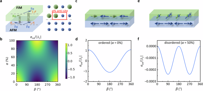
a Schematic diagram illustrating the geometry of the FiM-AFM coupling model (left) and the presence of anti-site defects in double-perovskite (right). The green (blue) layer corresponds to the SFRO (LFO) layer. The blue (green) arrows represent the Fe (Re) spins. b Numerical simulation results of the interfacial magnetic coupling energy (σint), normalized by the exchange coupling constant |J1 | , as a function of FiM magnetization direction (angle β) and cation order parameter (α). c Schematic of spin configuration and d the β angle dependence of σint for the SFRO-LFO with fully ordered SFRO (α = 0%). The results indicate the interface prefers a collinear coupling with a large coupling strength. e Schematic of spin configuration and f the β angle dependence of σint for the SFRO-LFO with fully disordered SFRO (α = 50%), showing a spin-flop coupling across the interface.
Next, we considered two extreme cases, i.e. heterostructures with fully ordered and fully disordered SFRO. First, for the fully ordered interface (α = 0%), the interfacial energy minimum locates at β = 180° as shown in Fig. 4d, revealing that the collinear coupling between moments of SFRO and LFO is energetically more favorable as schematically shown in Fig. 4c. Figure 4d also reveals that the reversal of FiM magnetization (from β = 180° to β = 0°) needs to overcome a relatively high energy barrier, which thereby explains the strong pinning effect and high thermal stability observed here. By contrast, at the fully disordered interface (α = 50%), the position of energy minimum (β = 90° or 270°) in Fig. 4f indicates that spin-flop coupling is more favorable, in which the magnetic moments of SFRO and LFO are orthogonally coupled as schematically shown in Fig. 4e. Under this circumstance, the coupling mechanism becomes similar to the typical FM-AFM interfaces such as LSMO-LFO21,42, and the coupling strength depends on the finite moments of FiM layer and the small canted moments in AFM layer. The relatively weak interfacial coupling strength at the disordered interfaces is further revealed by Fig. 4f, showing a much lower energy barrier for magnetization reversal as compared to Fig. 4d. This modeling analysis is further supported by the decrease of HEB observed in SFRO-LFO heterostructures with slightly lower B-site cation ordering (see Fig. S5), underscoring the potential role of ordered FiM spin structures.
Discussion
The modeling analysis above provides a plausible explanation for the enhanced EB. However, in practice, the LFO could adopt multiple antiferromagnetic domains and antiphase boundaries might also be present in SFRO, which could lead to different interfacial coupling configurations that affect the overall EB (see Figs. S6, S7). To gain insights into this issue, we have carried out further measurements on the correlation between EB and the magnetic field applied during field cooling. The results show that the EB is almost zero without cooling field and largely enhances as the cooling field increases from 1 T to 5 T (see Fig. S6a). The absence of EB at zero cooling field is consistent with the presence of regions with different interfacial coupling configurations in our heterostructures. Moreover, the application of cooling field is likely to modulate the interfacial couplings of different regions towards energetically more favorable states, leading to the enhancement of overall HEB as increasing cooling field (see more discussions in Note S2).
Our results thereby implicate the potential roles of ordered B-site cations and high crystalline quality in enhancing the interfacial coupling strength and EB. Note that cation disorder is still observable in some regions near the interfaces in our samples, although most of SFRO maintains a high degree of B-site cation ordering (see Fig. S2). Therefore, we could expect further improvements of the interfacial coupling energy and TB by optimizing the atomic structures at the interfaces. Moreover, by extending LFO to multiferroic BFO, our interface architectures could propel the frontier of all-oxide spintronic devices based on exchange bias, which broadens the horizons for electric-field controlled magnetism at room temperature.
In conclusion, we have designed and synthesized the heterostructures with G-type antiferromagnetic LFO and double-perovskite ferrimagnetic SFRO with highly ordered B-site cations. An enhanced EB is observed in the SFRO-LFO heterostructures, showing large increases of both exchange bias field and blocking temperature as compared to the typical FM-AFM systems such as LSMO-LFO. We further show that the cation ordering and ferrimagnetic spin structure likely contribute to the enhanced interfacial magnetic coupling. Our results open up new avenues for designing the oxide interfaces for spintronic applications.
Methods
Fabrication of SFRO-LFO heterostructure
We used pulsed laser deposition (PLD) with a KrF excimer laser (248 nm) to grow high-quality SFRO-LFO heterojunctions epitaxially on SrTiO3 (001) substrate. The substrate temperature was 750 °C in an oxygen ambience of 50 mTorr for LFO, while the parameters for SFRO was 775 °C and 15 ~ 20 mTorr. The laser energy density was ~1.5 J/cm2 and repeated at 5 Hz. The distance between substrate and target was 45 ~ 50 mm. After growth, the samples were cooled to room temperature at a rate of 12 °C/min.
Structural characterization
The crystal structure of SFRO-LFO was characterized by X-ray diffraction (XRD, Malvern PANalytical Empyrean) with Cu-Kα radiation (λ = 0.1542 nm). Cross-sectional sample for TEM was prepared by Zeiss Auriga focus ion beam (FIB), and was polished using 500 eV Ar+ ions in Nanomill instrument. The STEM-HAADF results were acquired on a FEI Titan Cubed Themis 60–300 microscope operated at 300 kV, which can provide a spatial resolution of ∼0.059 nm for STEM. The collection angle of the HAADF was 64–200 mrad with a probe forming semi-angle of 25 mrad.
XAS and XMCD
The XAS and XMCD measurements were carried out at BL07U beamline at Shanghai Synchrotron Radiation Facility (SSRF) in Shanghai, China, with a beam spot size of ~100×50 um in the energy range 690 ~ 740 eV. The incident angle is 30° to the sample surface and magnetic field is 5 T along the incident light. A single crystal α-Fe2O3 was measured for energy calibration.

Responses