Experimental verification of superconducting metamaterial quarter-wavelength transmission line resonators with non-uniform mode spacing

Introduction
The traditional superconducting transmission line resonators (TLRs), which support only the right-handed (RH) wave propagations in certain frequencies, have been applied in quantum information processing (QIP) in microwave bands. Typically, they are utilized to implement the strong couplings between superconducting qubits and microwave photons1,2, readouts of the superconducting qubits3, and microwave single-photon detections4,5, etc. Due to its linear dispersion, the mode distribution is linear, i.e., the frequency intervals between the nearest-neighbor modes are equal. As a consequence, it is required to achieve precise control of the working mode, i.e., avoid exciting all the other nearest-neighbor modes. If the fundamental mode with the frequency (omega _1) is selected as the working mode for the implementation of the desired QIPs, it is naturally required that the nearest-neighbor mode with a frequency of (omega _2=2omega _1) or a frequency of (omega _2=3omega _1) (for a quarter-wavelength resonator) should not be excited. This implies that the application of the usual TLRs to the QIPs with multi-photon driving techniques is practically a significant challenge6,7,8,9.
To overcome such a difficulty, left-handed (LH) TLRs or more practically composite right/left-handed (CRLH) TLRs, called generally the superconducting metamaterials (MTMs) ones with unconventional mode structures10,11,12,13, can be utilized alternatively. Here, the LH refers to the electric field, the magnetic field, and the wave vector do not satisfy the usual RH spiral relationship but satisfy the LH one14. Physically, the MTMs as typical artificial media, can be constructed by periodically arranging arrays of metal thin-wires or split-ring resonators15,16,17 and thus can possess the negative equivalent permittivity and negative equivalent permeability in the microwave band. Interestingly, Smith et al. first demonstrated the desired LH electromagnetic devices18 with simultaneously the negative equivalent permittivity and permeability19. Since then, a series of LH electromagnetic devices have been generated, typically such as the negative refractive antenna array20, metamaterial absorber21,22,23, phase shifters24, amplifiers25, and leaky-wave elements26,27, etc. for various novel applications.
Note that almost all MTM devices practically reveal the CRLH behaviors, i.e., showing the LH feature in the low-frequency band and the RH one in the high-frequency band, respectively. Basically, this is because each unit cell of the MTMs is realized by the RH capacitance and inductance, and corresponding parasitic capacitance and parasitic inductance, through the circuit reconfiguration. For example, the CRLH transmission line (TL) is actually generated by a unit cell consisting of a series of lumped-element reactances (including the RH capacitance and inductance)28,29. As a consequence, it possesses a wider working bandwidth and a lower loss. Benefited from the nonlinear dispersion relation, i.e., the frequency is nonlinearly related to the wave vector, the CRLH-TLs had been utilized to generate various novel electromagnetic devices, including typically as the dual-band components30, diplexers31, directional coupler32,33, negative and zeroth-order resonator34, filter35 and leaky-wave antenna36, etc. More interestingly, the nonlinear dispersion relation in the CRLH-TLRs induces the unconventional mode structures, which might deliver certain unconventional applications37,38,39,40, as various unwanted crosstalk effects between the adjacent modes can be effectively surpassed41. Inspired by the recent experimental demonstrations39 of the unconventional mode structures in half-wavelength CRLH-TLRs, in the present work we focus alternatively on the experimental demonstration of the mode structures in the quarter-wavelength CRLH-TLRs. The results show clearly that the modes can be well controlled without generating crosstalk. Thus these devices might also provide certain novel applications for the QIPs based on the multi-mode driven circuit QEDs and also the sensitive resonator-based single-photon detections.
The paper is organized as follows. Firstly, to alleviate the design complexity of the device, we confirm that the microwave transport properties of a quarter-wavelength RH-TLR can be conveniently analyzed by using the approach proposed in Ref.42, which we called the real-space approach here to distinguish it from the usual equivalent circuit method43. Secondly, with such an analysis, we theoretically analyzed the microwave transport properties of the quarter-wavelength CRLH-TLRs with three unit cells and conducted numerical calculations. Then, we specifically demonstrate the design and fabrication of the microstrip quarter-wavelength CRLH-TLR with three unit cells, then the simulation and measurement of their (S_{21})-parameter at 50 mK low-temperature. The results show that the mode distribution in the demonstrated superconducting MTMs quarter-wavelength CRLH-TLR is nonlinear, i.e., the frequency intervals between the nearest-neighbor modes are non-uniform. Thus each of them can be well controlled without generating crosstalk. Finally, we summarize our work.
A real-space approach to analyze the microwave scattering properties of a quarter-wavelength RH-TLR
Traditionally, the microwave transport properties of the devices are analyzed by using the well-known equivalent circuit method, wherein a series of equivalent circuits are constructed to effectively describe the lumped-element units. Beginning with a brief review of how such a method can be used to analyze the transport properties of the traveling microwaves scattered by a quarter-wavelength RH-TLR, we then show that the same problem can be treated more conveniently using the real-space approach. Such a comparison aims to confirm the validity of this method, which will be used to analyze the transport properties of the traveling microwaves scattered by the CRLH devices in the following sections.
The (S_{21})-parameter analysis using the usual equivalent circuit method
Following43, the transport properties of the traveling microwaves scattered by a quarter-wavelength RH-TLR can be described by the equivalent circuit method, shown in Fig. 1, where the total inductance, capacitance, resistance are L, C, R, respectively. Also, (V_1^{+}) and (V_1^{-}) are the incident and reflected voltages at port 1, (V_2^{+}) and (V_2^{-}) are the incident and reflected voltages at port 2, and (I_1) is the incident current at port 1.

A circuit model to analyze the transporting parameters of a quarter-wavelength RH-TLR43.
To simplify the circuit analysis, based on the Norton equivalent principle43, the Norton equivalent impedance is (Z_g=Z_0/2+1/(jomega C_c)) with (C_c) is the coupling capacitance, (omega) is the angular frequency, and (Z_0) is the impedance, as shown in Fig. 2a, the corresponding equivalent admittance is (Y_g=1/Z_g=jomega C_{c}+1/R_{g}(omega )) with (R_g(omega )=2Z_0/(Z_0omega C_c)^{2}); the Norton equivalent current is (I_g=V_g/(2Z_g)) as shown in Fig. 2b, where (V_g) is the voltage source; the Norton equivalent circuit of Fig. 1 is shown in Fig. 2c, and the equivalent voltage source is (V(t)=V_gR_{Vert }/{2Z_g[1+2jQ_r(f-f_r)/f_r]}) with (R_{Vert }=1/[1/R+1/R_g(omega )]) being the total resistance as shown in Fig. 2d, respectively. Also, (Q_rapprox omega _rR_{Vert }C) is the total quality factor, (Q_iapprox omega _rRC) is the internal quality factor and (Q_capprox omega _rR_g(omega )C) is the coupling quality factor, respectively, and they satisfy (Q_r^{-1}=Q_i^{-1}+Q_c^{-1}). The resonant angular frequency of the quarter-wavelength RH-TLR reads (omega _r=2pi f_r=1/sqrt{L(C+C_c)}) with (f_r) is the resonant frequency.
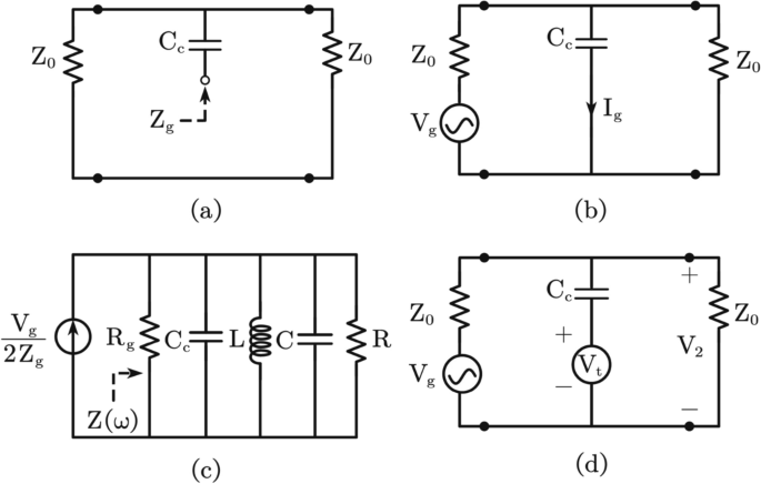
The equivalent circuit diagrams43: (a) The Norton equivalent impedance (Z_g); (b) The Norton equivalent current (I_g); (c) The equivalent circuit of the one shown in Fig. 1; (d) The resonant circuit is replaced by a voltage source (V_t).
with the above analysis, the (S_{21})-parameter, i.e.,
can be obtained. It is emphasized that this derivation just works for the TLRs under the well impedance-matching condition. The comprehensive analysis of the (S_{21})-parameter for the practically impedance-mismatched resonators has been provided in Ref.44. Also, the method to more accurately extract the (Q_i) and (Q_c) parameters, and then fit the value of (Q_r) can be found in Ref.45. Formally, the (S_{21})-parameter of a quarter-wavelength RH-TLR can be schematically shown in Fig. 3, where the total inductance and capacitance are set as (L=5.2) nH and (C=1.08) pF, and the coupling capacitance is (C_c=1) pF, and thus the resonant frequency is (f_r=1/[2pi sqrt{L(C+C_c)}]=1.53) GHz, the coupling quality factor and the total quality factor are (Q_c=300) and (Q_r=280.112), respectively. It can be found that in the usual equivalent circuit method43, a series of equivalent circuits are required to be constructed for the (S_{21})-parameter analysis. Because of this, various potential imperfections might be generated, and the complexity is greatly increased for the increase of the circuit scale.
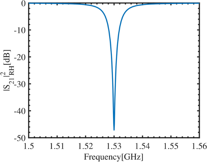
The (S_{21})-parameter near the resonant frequency (f_r=1.53) GHz of a quarter-wavelength RH-TLR, is calculated by using the equivalent circuit method. With the typical parameter as (L=5.2) nH, (C=1.08) pF, (C_c)=1 pF, (Q_r=280.112), and (Q_c=300), respectively.
A real-space approach to analyze the transport properties of a microwave-driven quarter-wavelength RH-TLR
In fact, the transport properties of the traveling microwaves scattered by various passive devices can be directly analyzed by alternatively using the approach proposed in Ref.42, which was used to analyze the transport properties of the half-wavelength RH-TLR in Ref.42, and which we will call the real-space approach. In this subsection, we will use this approach to analyze traveling microwaves scattered by quarter-wavelength RH-TLR.
In general, for a small segment length in RH-TL, i.e., the unit cell length (Delta x), as shown in Fig. 4a, where the inductance, capacitance, resistance and conductance per unit length are defined as (L=Delta L/Delta x), (C=Delta C/Delta x), (R=Delta R/Delta x), and (G=Delta G/Delta x), respectively. In the continuum limit (Delta xrightarrow 0), according to Kirchhoff’s law, the telegraph equations for the voltage V(x, t) and current I(x, t) transmitted by the microwave along the RH-TL are
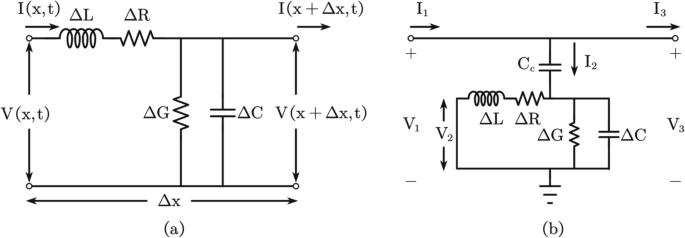
(a) The RH-TL unit cell circuit model, where the unit cell length is (Delta x). (b) A circuit model to investigate the (S_{21})-parameters of a quarter-wavelength RH-TLR, wherein (C_{c}) is the capacitance of the resonator being coupled to the feedline, (V_{2}) represents the voltage across the resonator, (V_{1}) and (V_{3}) are the input and output voltages of the resonator, respectively.
Then, the wave equation of RH-TL can be obtained as
wherein (A={I,V}), and in the frequency domain we have
where (gamma =sqrt{ZY}=alpha +jbeta (omega )) is the propagation constant, (alpha ={{RG-omega ^2LCpm [(RG-omega ^2LC)^2+omega ^2(RC+LG)^2]^{1/2}}/2}^{1/2}) is the attenuation coefficient, and (beta (omega )={{-(RG-omega ^2LC)pm [(RG-omega ^2LC)^2+omega ^2(RC+LG)^2]^{1/2}}/2}^{1/2}) is the phase constant, respectively. Also, the impedance and the admittance of the RH-TL are respectively as (Z=R+jomega L) and (Y=G+jomega C). Therefore, the traveling wave solution to Eq. (4) can be expressed as
where (Z_0=(R+jomega L)/gamma) is the characteristic impedance of the RH-TL, (V_0^{pm }) are the amplitudes of the voltage waves. Define a flux as (phi (x,t)=int _{-infty }^{t}V(x,tau )dtau) and substitute it into Eq. (3). The RH-TL is assumed to be lossless((R=G=0)), and the wave equation for the flux can be obtained as
where (v=omega /beta (omega )=1/sqrt{LC}) is the phase velocity. Therefore, we can get the dispersion relation of the RH-TL as
Letting (phi (x,t)=Q(t)u(x)), the generic solution to Eq. (6) can be written as
where B is a coefficient and (delta) is a constant, respectively. Physically, the boundary conditions: (I(x,t)=-partial _xphi (x,t)/L|_{x=0}=0) and (V(x,t)=partial _tphi (x,t)|_{x=l}=0) should be satisfied for a quarter-wavelength TLR with length l. This implies that, (delta =0) and
where only the standing wave modes n with the phase constants (beta _n(omega _n)) with the resonant angular frequency (omega _n=2pi f_n) and (f_n=nf_1) can exist in the resonator. Therefore, the mode expansion for the solution of the wave Eq. (6) can be made as (phi (x,t)=sum _nQ_n(t)u_n(x)). The mode functions (u_n(x)=C_1cos [beta _n(omega _n)x]) with the normalizing factor being (C_1=sqrt{2/l}) satisfy the following orthogonal relation (int _0^{l}|u_n(x)|^2dx=1). The voltage distribution in the typical standing wave mode allowed in the resonator as (V(x,t)=sum _{n=1}^{infty }V_n(t)cos [npi x/(2l)]) with (V_n(t)=-sqrt{2/l}omega _nsin (omega _nt)), where the length of TLR is (l=0.025) m, the inductance and capacitance per unit length are set as (L=0.33) (mu)H/m and (C=0.13) nF/m, the resonant frequency are set as (f_1=1/(4lsqrt{LC})=1.53) GHz, (f_3=3f_1=4.59) GHz, and (f_5=5f_1=7.66) GHz, as shown in Fig. 5.
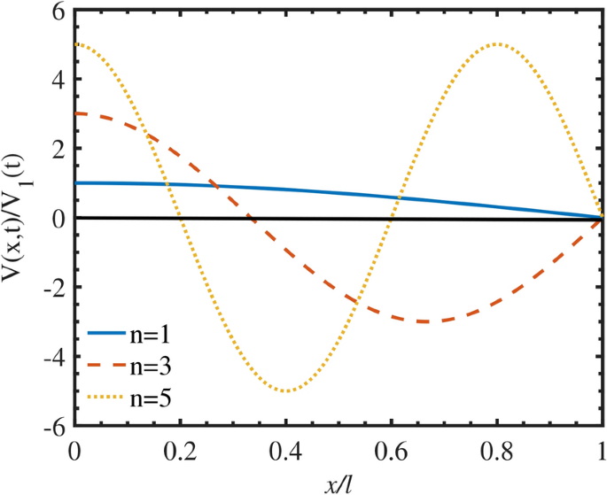
The voltage distributions of a quarter-wavelength RH-TLR and the corresponding standing wave modes are (n=1), 3, and 5, respectively. The typical parameters are set as: (l=0.025) m, (L=0.33) (mu)H/m, (C=0.13) nF/m, (f_1=1.53) GHz, (f_3=4.59) GHz, (f_5=7.66) GHz, (sin (omega _nt)=1), and (V_1(t)=-sqrt{2/l}omega _1).
Now, let us consider the transport properties of the traveling microwaves scattered by a quarter-wavelength RH-TLR with a length l, shown in Fig. 4b. The current and voltage waves in the i-th ((i=1), 2, 3) region can be formally expressed as
Assuming that the feedline has matched termination, yielding (V_{3}^{-}=0). As a consequence, at the points (x=pm 1/2) the following continuity conditions:
should be satisfied. Substituting Eq. (11) into Eq. (10), we get the transmission coefficient
wherein (theta =omega _nC_{c}Z_{0}), (omega _n) and (C_c) are resonant angular frequencies and coupling capacitance, respectively. Specifically, for the near-resonant driving, i.e., the frequencies of the traveling microwaves are set as (omega approx omega _n+delta omega) with (omega _n=2pi f_n) and (f_{n}=nf_1) with (n=1), 3, 5…. The fundamental frequency of the quarter-wavelength RH-TLR46 is (f_1=1/(4lsqrt{LC})), and the resonant frequencies of the third and fifth resonant modes are (f_3=3f_1) and (f_5=5f_1), respectively. Also, we have (e^{-2gamma l}approx [npi (f-f_n)j]/f_n+2alpha l-1) and (e^{2gamma l}approx -[npi (f-f_n)j]/f_n-2alpha l-1). Therefore, the (S_{21})-parameter of the resonator can be calculated as46
where (P_{out}(x=l/2)) and (P_{in}(x=-l/2)) are the output and input powers, respectively. Also, (V_{in}(x)=V_{1}^{+}e^{-gamma x}), (I_{in}(x)=V_{1}^{+}e^{-gamma x}/Z_{0}), (V_{out}(x)=V_{3}^{+}e^{-gamma x}), and (I_{out}(x)=V_{3}^{+}e^{-gamma x}/Z_{0}), respectively.
In fact, the (S_{21})-parameter of the device can be conveniently determined by using Eq. (13) and this is the obvious advantage of the real-space approach over the usual equivalent circuit approach, as any equivalent circuit is unnecessary to be constructed. The transport properties of the quarter-wavelength RH-TLR are numerically calculated and the (S_{21})-parameter are obtained as shown in Fig. 6, where the characteristic impedance of the TLR and the feedline is set to (Z_{0}=50) (Omega), the fundamental frequency is set as (f_1=1.53) GHz with the capacitance per unit length is (C=0.13) nF/m and the inductance per unit length is (L=0.33) (mu)H/m, the length of TLR is (l=0.025) m, the coupling capacitance is (C_{c}=1) fF, and the loss is approximated to be (alpha approx 1.84times 10^{-5}) m(^{-1}), respectively. The results show that the transmitted dips are respectively centered at the resonant frequencies (f_{1}=1.53) GHz, (f_{3}=4.59) GHz, and (f_{5}=7.66) GHz, and correspond to the standing wave modes (n=1), 3, 5 allowed in the resonator. It is seen clearly that the odd-multiple relation is satisfied between two adjacent frequency points due to the linear dispersion relation in Eq. (7) of the RH-TL. Therefore, the transport properties of a quarter-wavelength RH-TLR can be analyzed by using either the usual equivalent circuit approach or the real-space approach here. However, the real-space approach is more intuitive, as the relevant physical parameters are directly used without any equivalent approximation. Based on this fact, in the following, we perfect the real-space approach to investigate the transport properties of the quarter-wavelength CRLH-TLR.
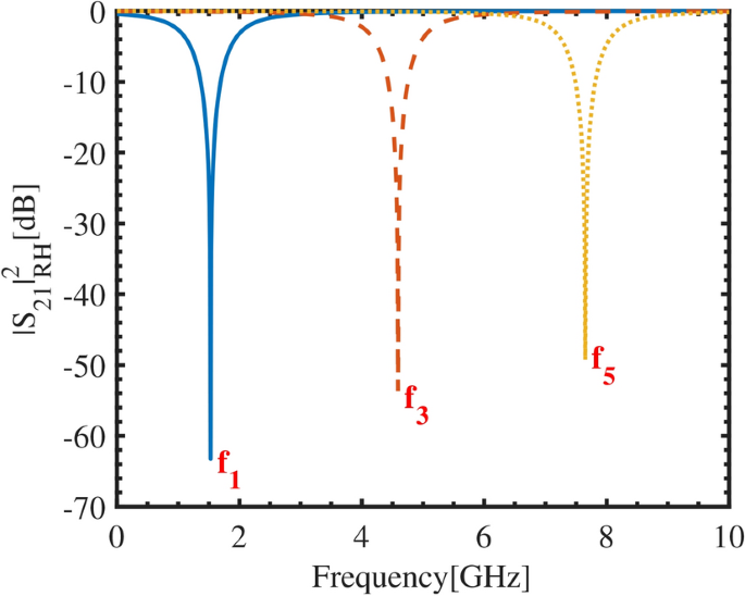
The (S_{21})-parameter of a quarter-wavelength RH-TLR is calculated by using the real-space approach in Eq. (13). The typical parameters are set as (f_1=1.53) GHz, (f_3=3f_1=4.59) GHz, (f_5=5f_1=7.66) GHz, (Z_{0}=50) (Omega), (l=0.025) m, and (C_{c}=1) fF, respectively. The loss of the resonator is approximated as (alpha approx 8(pi f_1C_cZ_0)^{2}/l) with (alpha approx 1.84cdot 10^{-5}) m(^{-1}).
Traveling microwave scattered by a quarter-wavelength CRLH-TLR
Beginning with a brief review of the basic theory of the CRLH-TL29,47, in this section, we theoretically analyze the mode structure of a quarter-wavelength CRLH-TLR and then use the real-space approach developed above to investigate the microwave transport properties of the designed quarter-wavelength CRLH-TLR.
A basic theory on CRLH-TL
In fact, the ideal CRLH-TL does not exist in nature. However, when the guided wavelength is much larger than the unit cell length (Delta x), the CRLH-TL can be constructed by periodically cascading a series of uniform LC cells29,47. In practice, the LC cells in the CRLH-TL can be treated as sufficiently uniform, if either the unit cell length (Delta x) is less than 1/4 of the guided wavelength (lambda _g) or the cell electrical length is less than (pi /2).
The CRLH-TL unit cell is schematically shown in Fig. 7, where (Delta x) is unit cell length, (L_{r}^{‘}=L_{r}/Delta x), (L_{l}^{‘}=L_{l}Delta x), (C_{r}^{‘}=C_{r}/Delta x), (C_{l}^{‘}=C_{l}Delta x), (R^{‘}=R/Delta x), and (G^{‘}=G/Delta x) are the RH-(LH-) inductance, RH-(LH-) capacitance, resistance, and conductance per unit length, respectively. The voltage V(x) and current I(x) wave equations in the frequency domain of CRLH-TL can be expressed as
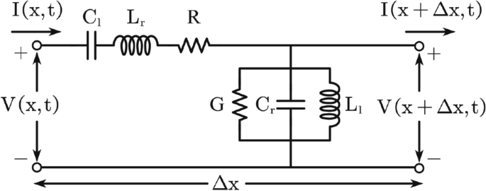
A circuit model of a CRLH-TL unit cell with the length of (Delta x), which includes series inductance (L_r) and shunt capacitance (C_r), and series capacitance (C_l) and shunt inductance (L_l), respectively. The series inductance and shunt capacitance provide RH characteristics, while the series capacitance and shunt inductance provide LH characteristics.
wherein (A_1={I,V}). Also, (gamma ^{‘}=sqrt{Z^{‘}Y^{‘}}=alpha ^{‘}+jbeta ^{‘}(omega )) is the propagation constant of the CRLH-TL, (alpha ^{‘}=[(A_2pm sqrt{A_2^2+A_3^2})/2]^{1/2}) is the attenuation coefficient with (A_2=R^{‘}G^{‘}-[omega L_r^{‘}-1/(omega C_l^{‘})][omega C_r^{‘}-1/(omega L_l^{‘})]) and (A_3=G^{‘}[omega L_r^{‘}-1/(omega C_l^{‘})]+R^{‘}[omega C_r^{‘}-1/(omega L_l^{‘})]), and
is the phase constant of the CRLH-TL, respectively. The impedance and the admittance of the CRLH-TL are (Z^{‘}=jomega L_{r}^{‘}+1/(jomega C_{l}^{‘})+R^{‘}) and (Y^{‘}=jomega C_{r}^{‘}+1/(jomega L_{l}^{‘})+G^{‘}), respectively. The traveling wave solution to Eq. (14) reads
where (Z_{0}^{‘}=[jomega L_{r}^{‘}+1/(jomega C_{l}^{‘})+R^{‘}]/gamma) is the characteristic impedance of the CRLH-TL, and (V^{pm }) are the amplitudes, respectively.
Modes distribution of a quarter-wavelength CRLH-TLR
Now, we investigate the mode distribution of a quarter-wavelength CRLH-TLR. As with RH-TL, also defining a flux as (phi (x,t)=int _{-infty }^{t}V(x,tau )dtau), the CRLH-TL is assumed to be lossless((R^{‘}=G^{‘}=0)), we have the following wave equation on the flux as
Letting (phi (x,t)=P(x)H(t)), we have
As a consequence, for spatial components we have
whose generic solution reads (P(x)=C_2cos [beta ^{‘}(omega )x+delta _1]) with (C_2) is a coefficient and (delta _1) is a constant, respectively. Specifically, for a quarter-wavelength CRLH-TLR of the length l, the device boundaries should satisfy the physical condition: (I(x,t)=[-C_r^{‘}int partial _t^2phi (x,t)dx-int phi (x,t)dx/L_l^{‘}]|_{x=0}=0) and (V(x,t)=partial _tphi (x,t)|_{x=l}=0), respectively. Therefore, we have (delta _1=0), which implies that only the standing wave modes n with the corresponding phase constant satisfy the condition:
can exist in the quarter-wavelength CRLH-TLR, where (omega _n=2pi f_n) is the resonant angular frequency. The voltage distribution in the typical standing wave mode allowed in the resonator as (V(x,t)=sum _{n=pm 1}^{infty }V_n(t)cos [npi x/(2l)]) with (V_n(t)=-sqrt{2/l}omega _nsin (omega _nt)), where the length of TLR is (l=0.025) m, the resonant frequency are set as (f_{-5}=0.90) GHz, (f_{-3}=1.08) GHz, (f_{-1}=1.52) GHz, (f_{+1}=2.30) GHz, (f_{+3}=3.24) GHz, and (f_{+5}=3.86) GHz, as shown in Fig. 8.
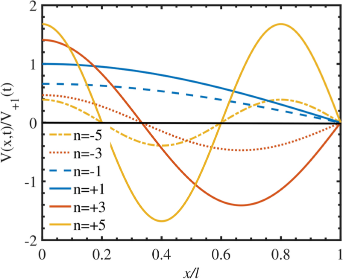
The voltage distributions of a quarter-wavelength CRLH-TLR and the corresponding standing wave modes are (n=pm 1), (pm 3), (pm 5), respectively. The typical parameters are set as (l=0.025) mm, (f_{-5}=0.90) GHz, (f_{-3}=1.08) GHz, (f_{-1}=1.52) GHz, (f_{+1}=2.30) GHz, (f_{+3}=3.24) GHz, (f_{+5}=3.86) GHz, (sin (omega _nt)=1), and (V_{+1}(t)=-sqrt{2/l}omega _{+1}).
However, for the practical CRLH-TL with the length (l=NDelta x), where N is the number of unit cells, the discrete modes in a quarter-wavelength CRLH-TLR should be replaced as34
which means that the number n of the allowed standing wave modes depends on the number of the unit cells N. Note that here, the phase constant (beta _n^{‘}(omega _n)) being the negative refers to the backward waves48. Differing from the RH-TLR, wherein the number of the modes is infinite, the allowed modes in the present CRLH-TLR are limited, i.e., the number of the allowed modes should be limited in the Brillouin zone of the phase costants as shown in Fig. 9. The Brillouin zone is divided into N regions with a width of (pi /l), the phase costants of the allowed modes that should be taken are (beta _n^{‘}(omega _n)) with (n=pm 1, pm 3,…, pm (2N-1)). Thus, the number of the allowed modes in a CRLH-TLR are limited by the number of its cells, and the number of all the allowed modes is 2N47. By applying the Bloch-Floquet theory to the cells, the corresponding dispersion relation reads47
and its bandwidth is limited by the LH highpass cutoff frequency and RH lowpass cutoff frequency. In the range (min(omega _{se},omega _{sh})<omega <max(omega _{se},omega _{sh})) with (omega_{se}=1/sqrt{L’_rC’_l}) and (omega_{sh}=sqrt{C’_rL’_l}) are respectively the series resonant frequency and shunt resonant frequency, electromagnetic waves cannot propagate and are in the gap band, which is a unique characteristic of CRLH-TL47.
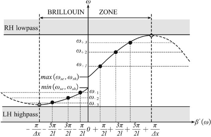
The dispersion relation of a periodic LC network quarter-wavelength CRLH-TLR composed of N unit cells (Here (N=3)). The grey areas represent the RH lowpass and the LH highpass regions, respectively47.
It can be seen that the dispersion relation of the CRLH-TL is nonlinear and different from the linear one shown in Eq. (7) for the usual RH-TL. Therefore, certain novel functions could be realized by using the CRLH-TL devices. Probably, this is the basic physical origination of various novel features, which the usual RH devices cannot possess.
A real-space approach to calculate the (S_{21})-parameters of a quarter-wavelength CRLH-TLR
Below, we investigate the transport properties of a quarter-wavelength CRLH-TLR by using the real-space approach, rather than the equivalent circuit approach. Let us consider a more practical configuration shown in Fig. 10 for the traveling microwave scattering, wherein a quarter-wavelength CRLH-TLR with N unit cells is capacitively coupled to an RH feedline. As a consequence, the current and voltage in the i-th ((i=1), 2, 3) region, can be described as
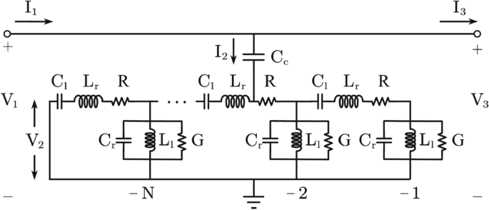
A practical circuit model for the traveling microwave transporting along the feedline and being scattered by a quarter-wavelength CRLH-TLR with N unit cells.
Here, we set (gamma _1^{‘}=gamma _3^{‘}=gamma), (gamma _2^{‘}=gamma ^{‘}), and (Z_0=Z_0^{‘}=50Omega) for the impedance matches. The boundary conditions, i.e., at the points (x=0) and (x=-NDelta x), could be expressed as
Again, assuming that the feedline has matched termination, and thus (V_{3}^{-}=0). Instituting Eq. (24) into Eq. (23), we have
wherein (theta ^{‘}=omega _nC_{c}Z_{0}^{‘}) and
respectively. As a consequence, the transmission coefficient of the traveling microwave scattered by a quarter-wavelength CRLH-TLR can be expressed as
through the resonator. Specifically, for the near-resonant driving, i.e., the frequencies of the traveling microwave are set as (omega approx omega _n+delta omega) and satisfied (omega _n=2pi f_n). Here, (f_n) specifically reads as
with (A_4=(L_r/L_l+C_r/C_l)-2cos [(npi )/2N]+2) by using the nonlinear dispersion relation is shown in Eq. (22). Also, we have (D=e^{2gamma ^{prime}NDelta x}approx -(1+2alpha ^{prime}NDelta x)), (E=e^{-2gamma NDelta x}approx -1+[npi (f-f_n)j]/f_n), (F=e^{2(gamma ^{prime}-gamma )NDelta x}approx 1+2alpha ^{prime}NDelta x-[npi (f-f_n)j]/f_n), and (M=e^{(gamma ^{prime}-gamma )NDelta x}approx 1+alpha ^{prime}NDelta x-[0.5npi (f-f_n)j]/f_n), respectively. Finally, the (S_{21})-parameter of a quarter-wavelength CRLH-TLR can be obtained as
where (P_{out}(x=0)) and (P_{in}(x=-NDelta x)) are the output and input power, respectively. Also, (V_{in}(x)=V_{1}^{+}e^{-gamma x}), (I_{in}(x)=V_{1}^{+}e^{-gamma x}/Z_{0}), (V_{out}(x)=V_{3}^{+}e^{-gamma x}), and (I_{out}(x)=V_{3}^{+}e^{-gamma x}/Z_{0}), respectively.
Figure 11 plots the (S_{21})-parameter of a quarter-wavelength CRLH-TLR by numerical calculation, where the typical device parameters are set as (C_{r}=3.44) pF, (L_{l}=2.11) nH, (C_{l}=2.31) pF, (L_{r}=3.14) nH, the length of TLR is (l=0.025) m, the coupling capacitance is (C_{c}=1) fF, and the loss is approximated to be (alpha ^{prime}approx 4.18times 10^{-5}) m(^{-1}), respectively.
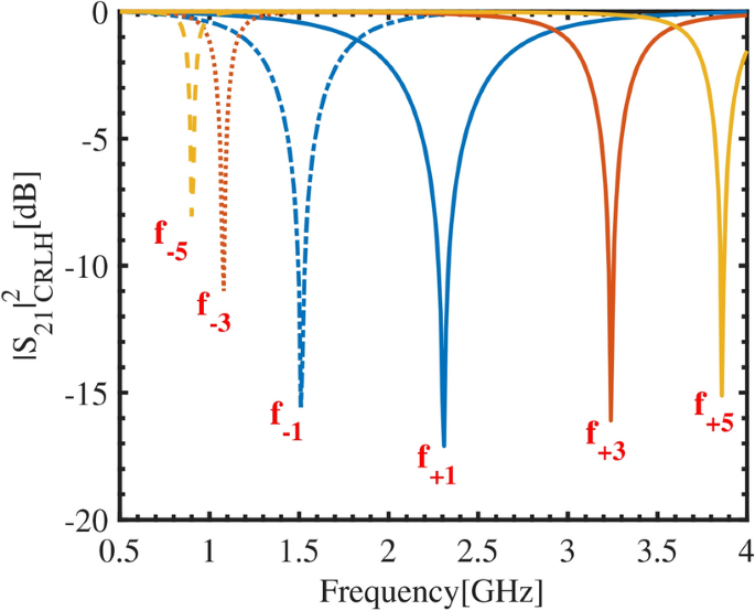
The (S_{21})-parameter of a quarter-wavelength CRLH-TLR, with the typical parameters32: (C_{r}=3.44) pF, (L_{l}=2.11) nH, (C_{l}=2.31) pF, (L_{r}=3.14) nH, (C_{c}=1) fF, and (l=NDelta x=0.025) m, respectively. Here, the number of the unit cells is set as (N=3) and the standing wave modes scattered by the resonator are taken as (n=pm 1), (pm 3), (pm 5), respectively.Here, the resonant frequency corresponding to the (n=+1) order standing wave mode can be obtained as (f_{+1}=2.30) GHz from Eq. (28), and the loss of the resonator is approximated as (alpha ^{prime}approx 8(pi f_{+1}C_cZ_0^{prime})^{2}/l) with (alpha ^{prime}approx 4.18cdot 10^{-5}) m(^{-1}).
It is seen really that the six transmitted dips are respectively observed at frequency points (f_{-5}=0.90) GHz, (f_{-3}=1.08) GHz, (f_{-1}=1.52) GHz, (f_{+1}=2.30) GHz, (f_{+3}=3.24) GHz, and (f_{+5}=3.86) GHz, and the corresponding standing wave modes (n=pm 1), (pm 3), (pm 5) allowed in the resonator. These numerical results are consistent with the analytical ones demonstrated above. Due to the nonlinear dispersion in Eq. (22), the standing wave modes of the quarter-wavelength CRLH-TLR with non-uniform frequency intervals are distinguished from the RH-TLR with uniform frequency intervals.
A microstrip superconducting quarter-wavelength CRLH-TLR with three unit cells: design, fabrications and experimental measurements
Following Refs.34,49,50, we demonstrate the design, fabrication, and low-temperature experimental measurements of a microstrip superconducting quarter-wavelength CRLH-TLR with three unit cells. As shown in Fig. 12a, a circuit model of a microstrip superconducting quarter-wavelength CRLH-TLR with three cells is designed using electromagnetics simulation software, where each of the unit cell structures composed of a series of interdigital finger capacitor and a shunt stub inductor, and the substrate is SiO(_2). Specifically, the thickness of the substrate and the upper air medium layer is set as (h=2.2) mm and 2 mm, and the dielectric constant of the substrate is (varepsilon _{r}=3.7). The length and the width of the fingers are set as (l_{id}=10.2) mm and (w_{id}=0.3) mm, the number of fingers is 10, and the finger spacing is set as 0.2 mm, respectively. Also, the length of a shunt stub inductor is (l_{stub}=9.5) mm, with the width being (w_{stub}=2) mm. The gap between the microstrip feedline and the CRLH-TLR is set as 0.2 mm and (w=1) mm. The resonator is coupled to a microstrip feedline with a width of (W=4.8) mm and the characteristic impedance is set as 50 (Omega)46.
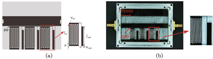
(a) Simulated prototype of microstrip superconducting quarter-wavelength CRLH-TLR with three unit cells and the corresponding unit cells; (b) Experimental samples. The size of the sample holder is (50.4times 35.4times 9.6) mm(^3), and the size of the sample is (50times 35) mm(^2). Here, the black part of the sample refers to the aluminum film coated on the substrate, with a thickness of 100 nm.
Based on the design demonstrated above, we fabricated the devices using the high vacuum electron beam evaporation coating technique to deposit the high-purity aluminum films on the SiO(_2) substrate and then used the laser direct writing lithography to generate the device patterns, and spot welding the sample onto the sample holder. Specifically, the aluminum target the material in the crucible is heated, melted, and evaporated by an electron gun, and then the aluminum gas was deposited onto the SiO(_2) substrate to generate a desirable aluminum film, and one of the generated samples is illustrated in Fig. 12b.
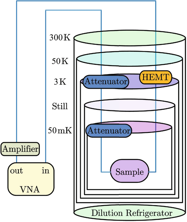
Schematic diagram of the experimental setup used to measure the transport properties of microwave signals at low temperatures, where the VNA is used to measure the (S_{21})-parameter of the device in the frequency domain.
The schematic diagram of the experimental setup is shown in Fig. 13, which consists of two parts: a frequency domain measurement system by a vector network analyzer (VNA) and a low-temperature measurement system by a dilution refrigerator. We fixed the sample on the MC plate of the dilution refrigerator, and when the internal temperature of the dilution refrigerator drops to 50 mK, the sample transforms into a superconductor. Here, in order to suppress the noises in the resonator, a (- 20) dB microwave attenuator was added to the 3 K and 50 mK plate in the dilution refrigerator. Then, the microwave signals through a transmission line were amplified by a cryogenic HEMT (High Electron Mobility Transistor) amplifier mounted on a 3 K plate inside the dilution refrigerator, and the (S_{21})-parameter of the microstrip superconducting quarter-wavelength CRLH-TLR with three unit cells measured by a VNA43.
The (S_{21})-parameter of the microstrip superconducting quarter-wavelength CRLH-TLRs with three unit cells are shown in Fig. 14. According to the parameter extraction approach32, the cell parameters of the CRLH-TLRs can be extracted as (C_{r}=3.44) pF, (L_{l}=2.11) nH, (C_{l}=2.31) pF, and (L_{r}=3.14) nH, respectively. The blue curve represents the simulation results of the (S_{21})-parameter, wherein the six transmitted dips centered at (f_{-5}=0.97) GHz, (f_{-3}=1.31) GHz, (f_{-1}=1.58) GHz, (f_{+1}=2.58) GHz, (f_{+3}=3.20) GHz, and (f_{+5}=3.58) GHz are obtained, respectively. The red curve represents the experimental measurement results of the (S_{21})-parameter of the fabricated device for the driving power being set as (- 50) dBm, which is relatively strong due to the circuit dissipation. It is seen that six transmitted dips, respectively centered at (f_{-5}=0.90) GHz, (f_{-3}=1.21) GHz, (f_{-1}=1.42) GHz, (f_{+1}=2.42) GHz, (f_{+3}=3.19) GHz, and (f_{+5}=3.86) GHz, are observed and their internal quality factors are approximately fitted as (Q_{-5}=1296), (Q_{-3}=14858), (Q_{-1}=4258), (Q_{+1}=31620), (Q_{+3}=15331), and (Q_{+5}=734). It can be seen that the experimental observed results and simulated ones for the negative resonances are well in agreement with the theoretical in Fig. 11. In the positive resonance regime, i.e., between (f_{+3}) and (f_{+5}), an additional dip is observed, which may be due to the crosstalk effect between the higher-order modes and parasitic effect47. Meanwhile, the existence of additional dips near (f_{+1}) in the measured results may be due to the “mixed mode” phenomenon generated by the strong coupling between the unit cells, which leads to mode splitting, as well as parasitic effects and preparation errors of the device47. Also, as the signals have been amplified by using the cryogenic HEMT amplifier, the measured (S_{21})-parameter is greater than zero. The resonant frequency points obtained from different approaches (i.e., the theoretical predictions, simulations, and experimental measurements) were compared in Table 1.
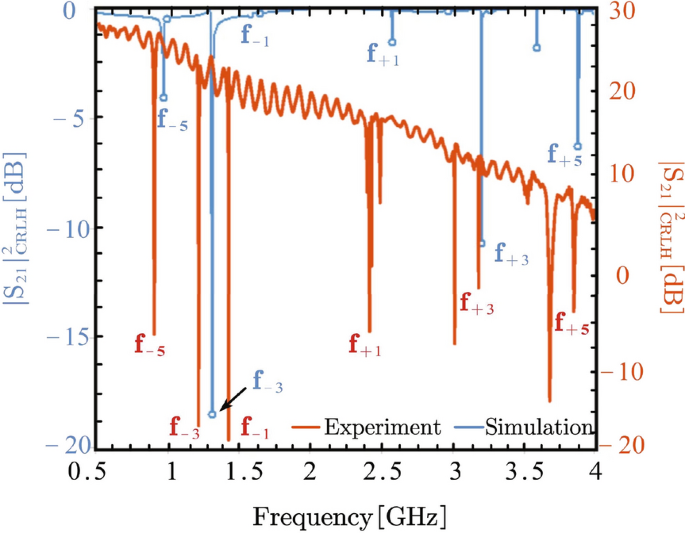
The microwave (S_{21})-parameter of the fabricated microstrip superconducting quarter-wavelength CRLH-TLR with three unit cells. Here, the blue curves refer to the simulations, and the red curves refer to the experimental measurements, respectively.
It can be seen from Table 1 that the experimental and simulation results are in general agreement with the theoretical predictions shown in Fig. 11, although there are some slight deviations between the frequency points obtained by different methods. More importantly, one can see that the measured frequency intervals between the nearest-neighbor modes are non-uniform, typically such as (f_{-3}-f_{-5}=0.31) GHz, (f_{-1}-f_{-3}=0.21) GHz, (f_{+1}-f_{-1}=1) GHz, (f_{+3}-f_{+1}=0.77) GHz, and (f_{+5}-f_{+3}=0.67) GHz, respectively. Therefore, the expected non-uniform mode spacings had been experimentally verified, although the observed internal quality factors of the transmitted dips are relatively low due to impurities and energy loss during the device preparations and microwave transport measurements. This indicates that, compared with the usual superconducting quarter-wavelength RH-TLRs with uniform frequency spacing, the demonstrated microstrip superconducting quarter-wavelength CRLH-TLRs could provide certain novel applications for the superconducting QIPs.
Conclusion
In summary, given the usual superconducting RH-TLRs have been widely applied to the microwave band QIPs, we experimentally demonstrated here that the superconducting CRLH-TLRs, as one of the MTMs devices, possess the non-uniform mode spacing. Beyond the usual equivalent circuit approach, we use a real-space approach to analyze microwave transport properties by using the physical characteristics of device boundaries. We have designed and fabricated the relevant devices, and experimentally measured their transport properties at low temperatures. The experimentally measured results agree with the simulated results and the theoretical predictions. The experiments verified that the CRLH-TLRs possess the desired non-uniform mode spacing. This not only verifies that the CRLH-TLRs possess the nonlinear dispersion relation, and thus could be utilized to encode the qubits for the superconducting QIPs.
Responses