Field-free spin-orbit torques switching and its applications

Introduction
The development of non-volatile resistive memories is essential for progress in future computing technologies, especially in the era of data-centric technology, such as the Internet of Things (IoT), big data, machine learning, and artificial intelligence1,2,3,4. Among them, magnetic random-access memory (MRAM) has demonstrated excellent characteristics, including fast operating speed, low power consumption, and superior reliability, making it a potential platform for future memory and logic applications5,6,7. The core building block of MRAM is a magnetic tunnel junction (MTJ), consisting of ferromagnetic free and pinned layers separated by a thin insulating barrier8,9,10. The tunneling magnetoresistance of the MTJ is determined by the magnetization alignment of the two ferromagnets (FMs), which enables storing digital information by switching the magnetization direction of the free layer while maintaining the magnetization of the pinned layer. This magnetization switching is achieved by using either a magnetic field or current-induced spin torques11,12,13,14.
Earlier MRAM utilized an Oersted field for magnetization switching15; however, this technique is not scalable. As the device size decreases, the coercivity of the free FM layer increases16, resulting in significantly higher power consumption to write information. Current MRAM successfully addresses this issue by employing current-induced spin torques, where the switching current scales down with device size17,18. Spin torques, which manipulate magnetization via the angular momentum exchange between spin currents and local magnetic moments, are classified as either spin-transfer torque (STT)13,14 or spin-orbit torque (SOT)19,20,21,22, depending on how the spin current (JS) is generated. STT involves a longitudinal JS generated by a charge current (JC) flowing through an FM layer via s–d exchange interaction. On the other hand, SOT exploits spin-orbit coupling effects, which generate a transverse JS via the spin Hall effect (SHE) in an adjacent non-magnet (NM), and/or the Rashba-Edelstein effect at the FM/NM interfaces (Fig. 1a).

a Spin-orbit torque, where a charge current (JC) in the x-direction creates spin current (JS) flowing in the z-direction, which accumulates spin polarization along the y-direction at the NM/FM interface. The purple and pink arrows represent the direction of spin polarization and the red and blue arrows indicate the magnetization direction of the free FM layers. b Schematic of a three-terminal SOT-MRAM.
Because of the difference in JS generation mechanism, SOT-MRAM exhibits several distinct characteristics compared to STT-MRAM23,24. First, SOT-MRAM employs a three-terminal device geometry, where the write current path is separated from the reading current paths, as shown in Fig. 1b. This separation enhances device reliability and increases read-disturb margin, as a large writing current does not flow through the thin tunnel barrier. In addition, SOT-MRAM can have a thicker tunnel barrier, potentially increasing TMR value25,26,27. Second, the spin polarization of the JS, which is orthogonal to both the JC and JS flow directions, is aligned in the film plane in a typical NM/FM bilayer. This configuration allows the SOT-MRAM to achieve fast switching of perpendicular magnetization within a sub-nanosecond28,29,30,31,32, as it eliminates the requirement of thermal fluctuations and the associated incubation time required in STT-MRAM. However, this orthogonal relation between the spin polarization and magnetization directions in conventional SOT imposes a critical limitation: the perpendicular magnetization cannot be deterministically switched without an external magnetic field (Bext) along the JC direction19,20,21,22. This Bext requirement makes device integration challenging.
To address this, various strategies for achieving field-free SOT switching have been investigated. This Perspective reviews two main approaches. The first involves a conventional SOT combined with different symmetry-breaking methods, and the second explores unconventional SOTs that generate out-of-plane spin polarization. Additionally, we discuss the potential applications of field-free SOT switching in innovative spintronic devices.
Conventional SOT with in-plane symmetry breaking
In-plane effective magnetic field
In conventional SOT structures consisting of a homogenous NM/FM bilayer, JC in the x-direction creates JS flowing in the z-direction, which accumulates spin polarization along the y-direction at the NM/FM interface. These accumulated spins generate a SOT that tilts the magnetization of the FM toward the y-direction. Once the JC and the associated SOT are removed, the magnetization returns to either the +z– or −z-direction with equal probability due to the perpendicular magnetic anisotropy (PMA). Therefore, deterministic switching of perpendicular magnetization does not occur with conventional SOT alone. When an in-plane Bext is applied along the x-direction, the SOT acts on the x-component of magnetization (mx) in the z-direction, given by [mx × y], determining a preferred direction of magnetization switching. This can be also explained by the symmetry argument. When JC flows along the x-direction, the system’s symmetry with respect to the x–z plane is preserved in the absence of Bext, which does not allow deterministic switching, as illustrated in Fig. 2a. In contrast, the application of Bext breaks the inversion symmetry, enabling a deterministic switching of perpendicular magnetization (Fig. 2b). One way to eliminate the requirement for Bext is to induce an in-plane effective magnetic field (Beff) by introducing an antiferromagnet (AFM) or an additional FM. The former harnesses an exchange coupling field from AFM in IrMn/CoFeB and PtMn/[Co/Ni] structures33,34, where AFM (IrMn or PtMn) also generates a sizable JS (Fig. 3a). Note that it is difficult to achieve an in-plane exchange coupling field at the AFM interface, when coupled with an FM that has a PMA. Y.-W. Oh et al. addressed this by introducing an additional FM CoFeB layer with in-plane anisotropy underneath the IrMn layer, which improved the in-plane exchange bias and facilitated reliable deterministic SOT switching33. The latter involves an in-plane Beff through magnetic coupling with other FMs35,36. For instance, an in-plane Beff could be generated via the Ruderman-Kittel-Kasuya-Yosida (RKKY) interaction35 or a dipolar coupling37,38 from an in-plane magnetized FM positioned away from the NM/FM structure. Note that this technique can be applied in actual devices; K. Garello et al. demonstrated deterministic SOT switching of MTJs on a 300-mm wafer by utilizing the dipolar field from 50-nm-thick Co FMs integrated away from the MTJ devices39.
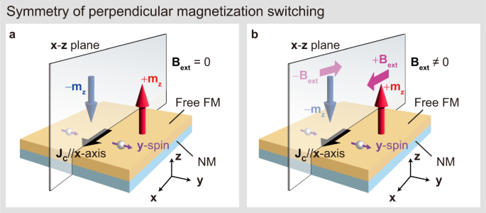
Schematics of the perpendicular magnetization (±mz), charge current (JC) along the x-direction, and y-spin under inversion symmetry along the x–z plane a, without and b, with external magnetic field (Bext).
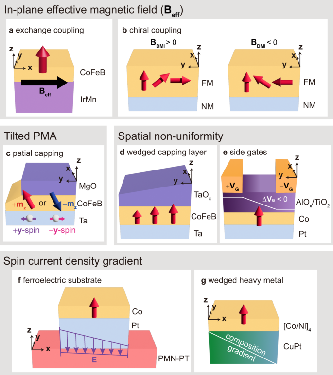
a Schematic of a CoFeB/IrMn bilayer, where IrMn generates the Beff via exchange coupling. b Possible magnetization configurations where the chiral symmetry is broken by the BDMI. c Schematic of tilted magnetic anisotropy in a Ta/CoFeB/MgO structure. The tilting is achieved by partially covering the CoFeB with MgO along the y-direction. Red and blue arrows indicate UP and DOWN magnetization states with y-component magnetization due to tilted magnetic anisotropy. d Schematic of a Ta/CoFeB/TaOx structure with wedge-shaped TaOx. e Schematic of the Pt/Co/AlOx structure with two side gates, where a gate voltage gradient (ΔVG(),) induces lateral modulation of the Rashba effect. f Schematic of a Pt/Co structure on top of a ferroelectric substrate (PMN-PT), where an electric field (E) gradient creates a spin current density. g Schematic of a CuPt/[Co/Ni]4 structure with a composition gradient along the x-direction. The red arrows indicate the magnetization direction of FMs, and JC flows in the x-direction in all schematics.
Another way to replace Bext involves exploiting a Dzyaloshinskii–Moriya interaction (DMI) field, BDMI40. The BDMI breaks the chiral symmetry of the SOT-induced non–collinear spin textures, leading to an energetically favorable magnetic state (Fig. 3b) that enables field-free SOT switching. This has been demonstrated in several structures, including a wedge-shaped CoGd or CoFeB layer on a Ta layer40, an epitaxial Pt/Co bilayer structure on a single- crystal MgO substrate41, a perpendicular magnetized CoTb ferrimagnet with a composition gradient along the z-direction42,43, and a Pt/Co/AlOx structure consisting of chiral-coupled perpendicular and in-plane magnetization regions44.
Tilted magnetic anisotropy
The SOT switching symmetry can be broken by employing an FM with tilted magnetic anisotropy from the perpendicular direction. In the case where the magnetization lies in the +y-+z plane, indicated by the red arrow in Fig. 3c, the SOT with +y spin rotates the magnetization toward the +y direction. However, due to the tilted anisotropy, it is unable to overcome the energy barrier for switching to the -z direction, making the UP magnetization (+mz) energetically favorable. Conversely, when applying SOT with −y-spin, the tilted magnetic anisotropy favors the DOWN magnetization (−mz), enabling deterministic SOT switching. This was demonstrated in a Ta/CoFeB/MgO structure, where the FM CoFeB was partially covered by the MgO layer (Fig. 3c)45. This technique has been applied to various magnetic materials: to conventional 3d-FM Co, with dislocations designed through the substrate’s miscut angle46,47; a [Co/Gd] multilayered ferrimagnet combining uniaxial in-plane and perpendicular magnetic anisotropies48; a SrRuO3 oxide FM with tilted magneto-crystalline anisotropy49; and a (Ga,Mn)As semiconductor FM with a non-uniform Mn distribution50. Note that these approaches, involving both Beff and tilted magnetic anisotropy, successfully achieved deterministic SOT switching, but inevitably induced an in-plane magnetization component in the free layer, which weakens PMA and the associated thermal stability.
Spatial non-uniformity
Another way of achieving field-free SOT switching is to introduce a special non-uniformity transverse to the JC direction (y-direction). Introducing spatial non-uniformity allows the spin torque to act preferentially in one direction. For example, in wedge-shaped structures, the gradual variation in capping oxide layer thickness along the y-axis creates a non-uniform distribution of magnetic properties such as magnetic anisotropy, across the structure. This non-uniformity breaks the inversion symmetry in the x–z plane, allowing for deterministic switching. Indeed, field-free SOT switching has been demonstrated in a Ta/CoFeB/TaOx structure with varying TaOx thickness (Fig. 3d)51 and in a Mo/CoFeB/MgO with varying Mo thickness52. Spatial asymmetry can be also introduced through microstructural modulations, such as slanted columnar Cr grains grown at a tilted angle in Cr/CoFeB/MgO53. Additionally, local microstructures can be modulated by external stimuli. For instance, local laser annealing or ion irradiation spatially modifies the stacking order of Co/Pt multilayers54 or the composition gradients in magnetic materials, such as CoGd55 or Co/Ni multilayers56, respectively.
Note that in the approaches mentioned above, once they have been established, the direction of spatial non-uniformity and the resulting field-free SOT switching polarity are fixed. Electrically controllable field-free SOT switching polarity has been reported by introducing two side gates in a Pt/Co/AlOx device, where a gate voltage gradient (ΔVG(),) induces lateral modulation of the Rashba effect (Fig. 3e)57,58. In this device, the polarity of field-free SOT switching can be reversed by changing the gate voltages, providing additional functionalities, including programable spin logic operations.
Spin current density gradient
Another approach to field-free SOT switching is to employ a spin current density gradient along the x-direction. K. Cai et al. created a spin current density gradient in a Pt/Co/Ni/Co/Pt structure grown on a ferroelectric substrate by utilizing electric field-induced ferroelectric polarization (Fig. 3f)59. This spin current density gradient generates an effective magnetic field (Beff ~ (partial {{bf{J}}}_{{bf{S}}}/partial {bf{x}})) along the x-direction, resulting in field-free switching. Field-free SOT switching by exploiting spin current density has also been demonstrated in samples with wedge structures along the x-direction, by varying W thickness in a Pt/W/[Co/Ni]4 structure60, or by varying CuPt composition in CuPt/[Co/Ni]4 (Fig. 3g)61. An alternative approach involves adjusting the geometry of the SOT device62,63,64, such as introducing a bending structure, where a JC generates a spatially non-uniform JS, enabling field-free SOT switching. This approach demonstrated scalability and compatibility with wafer-scale manufacturing processes.
Unconventional SOT with out-of-plane spin polarization
Low symmetry materials
This chapter describes another approach to field-free SOT switching by utilizing JS with out-of-plane spin polarization (z-spin). This is often referred to as unconventional SOT because it is absent in conventional SOT with isotropic materials. Unconventional SOT was first demonstrated in materials with low crystal symmetry, where a JC applied in a direction with broken mirror symmetry generates z-spin. WTe2 is a typical example of a low symmetry material, where z-spin was generated when JC flows along the a-axis (the low symmetry direction), as shown in Fig. 4a65. This unconventional SOT successfully demonstrated switching of perpendicular magnetization in WTe2/Fe2.78GeTe266, SrRuO3/WTe267, and WTe2/Ti/CoFeB/MgO heterostructures68 without Bext.
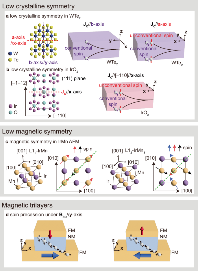
a Unconventional SOTs of in WTe2. The JC flowing to the a-axis (low symmetry direction) generates both y– and z-polarized JS. b Unconventional SOTs of IrO2. The JC flowing to the [−110] direction (low symmetry direction) along the red dashed line generates both y– and z-polarized JS. c Magnetic configuration of L10-IrMn and L12-IrMn3 and the magnetic mirror symmetry in the (001) plane. Arrows indicate magnetic moments with their orientations differentiated by colors. d Spin current generation with spin-orbit presession in magnetic trilayers. Here, an interfacial spin-orbit field (BSO) is induced at the NM/FM. The blue and red arrows in the ferromagnet indicate the magnetization direction. The black arrows represent the direction of spin polarization of JS when a JC flows in the x-direction.
Recently, it was reported that the spin Hall conductivity of z-spin can be enhanced by introducing a PtTe2/WTe2 bilayer, where the conventional y-spin generated in PtTe2 is effectively converted into z-spin WTe2 through spin-to-spin conversion69. Unconventional SOT has been also demonstrated in other low symmetry materials, including a L11-ordered CuPt/CoPt structure70 and a CoPt single layer71. For example, when JC is applied along the [1−10] direction in the CuPt (11−2) plane, the broken inversion symmetry gives rise to SOT with a z-spin, resulting in field-free SOT switching of the perpendicularly magnetized CoPt. The observed three-fold angular dependence of the field-free switching confirms the above symmetry argument, that z-spin appears only when JC is applied to a low symmetry direction of the CuPt layer. Note that unconventional SOT can be also observed in a high-symmetry material. M. Patton et al. reported that by controlling the crystal symmetry of IrO2 using epitaxial heterostructures, unconventional SOT with z-spin was observed in the IrO2 (111) plane when JC flows along the [−110] direction, where the inversion symmetry is broken, as shown in Fig. 4b72.
Low magnetic symmetry
Another way to generate unconventional SOT involves using materials with low magnetic symmetry, where the crystal symmetry is preserved, but the symmetry is broken by the presence of magnetic moments. For instance, the magnetic mirror symmetry is broken along the [110] direction in the (001) plane in L10-IrMn or L12-IrMn373,74, as shown in Fig. 4c, and therefore, JC along the [110] direction generates unconventional SOT with z-spin. Similarly, unconventional SOT was demonstrated in Mn2Au, as well as consequent field-free SOT switching in Mn2Au/[Co/Pd]3 heterostructure75. Note that this unconventional SOT observed in AFM with low magnetic symmetry is also known as the AFM SHE.
Recently, a new magnetic phase referred to as altermagnet has been theoretically and experimentally reported to generate unconventional SOT. Altermagnets have vanishing net magnetization due to their antiparallel magnetization alignment, similar to AFMs, but they can also generate spin currents like FMs because of their spin-split band structure76. The generated JS exerts a torque on the adjacent FM, which is also called spin-splitter torque. Moreover, the spin polarization of the spin current is determined by the altermagnetic order vector, allowing for the generation of either conventional or unconventional SOT depending on the crystal direction of the applied JC77. JSs with various spin polarizations, depending on the crystal direction, have been reported in altermagnet RuO278,79,80. Among these, field-free SOT switching driven by unconventional SOT with z-spin has been observed in (101)-textured RuO279.
Magnetic trilayers
The z-spin and the associated unconventional SOT can also be generated by exploiting an FM/NM/FM magnetic trilayer (Fig. 4d), where the JS generated from the bottom FM/NM layer exerts SOTs on the top FM layer81. In the FM/NM heterostructure, JS carries the spin polarizations in the conventional y-direction (y-spin), the magnetization direction of the FM (m-spin), and the (m × y) direction ((m × y)-spin). Note that y-spin is due to the spin Hall and Rashba-Edelstein effects and interfacial spin-orbit filtering, m-spin is due to the spin anomalous Hall and spin anisotropic magnetoresistance effects, and (m × y)-spin is due to the magnetic SHE and interfacial spin-orbit precession82,83.
In particular, when the bottom FM has an x-component of magnetization, (mx × y)-spin has a z-component, facilitating the field-free SOT switching of the top perpendicular magnetization. Furthermore, theoretical calculation suggested that an increase in the contribution of unconventional SOT with z-spin leads to a significant reduction in the critical SOT switching current density84. This unconventional SOT has been demonstrated in FM/NM/CoFeB/MgO structures, where the bottom FM is in-plane magnetized CoFeB and NiFe, and the NM is Ti, Ta, and W32,81,85,86,87,88. Furthermore, in the magnetic trilayers, all three spin components of y-, m-, and (m × y)-polarizations can be exploited by modulating the azimuthal angle of the m with respect to the JC. It was demonstrated that the field-free switching current of the CoFeB/Ti/CoFeB trilayer is considerably reduced by exploiting these three polarizations89.
Novel spintronics applications with field-free SOT switching
Emerging non-volatile memory applications
SOT offers the key advantage of fast operation as the state-of-the-art SOT-MRAM demonstrated sub-nanosecond field-free SOT switching (300 ps) in a three-terminal MTJ with a low writing error rate (<10−6) and high endurance (>1012)39. This makes non-volatile SOT-MRAM a strong candidate to replace volatile SRAM in high-speed applications like last-level caches. However, to be a more practical alternative, the SOT-MRAM switching current and resultant power consumption still needs to be reduced while maintaining field-free switching capabilities.
Several approaches have been proposed to achieve a lower critical switching current. The first approach involves combining other switching mechanisms with SOT, such as voltage-controlled magnetic anisotropy (VCMA) or STT. It has been reported that the SOT switching current can be modulated by controlling the magnetic anisotropy of the free layer using VCMA57,90. Further, E. Grimaldi et al. reported that combining VCMA and STT with SOT enhances switching efficiency and led to faster switching in CoFeB/MgO-based MTJs with a uniform and narrow switching current distribution31. The second approach is to increase the efficiency of JS generation by using JS sources with large spin-orbit coupling, such as topological insulators91,92,93,94,95 or Weyl semimetals65,66,67,68,69,96,97,98, or by employing unconventional SOT with z-spin32,81,85,86,87,89 as described in the previous chapter. Lastly, recent efforts have focused on reducing the SOT switching current by utilizing orbital currents arising from the orbital Hall effect and/or orbital Rashba-Edelstein effect99,100,101,102,103,104,105,106, following theoretical predictions that orbital Hall conductivity is much greater than spin Hall conductivity in most elements107,108,109.
Note that among the various field-free SOT technologies discussed in the previous chapter, those suitable for practical device applications must be compatible with complementary–metal–oxide–semiconductor (CMOS) processes and scalable to wafer-level implementation. Some techniques (e.g., tilted magnetic anisotropy, spatial non-uniformity, and low symmetry materials) will require further development to meet these criteria, while approaches utilizing dipolar fields from an additional FM layer or unconventional SOT in magnetic trilayer structures have already demonstrated wafer-level device implementation of field-free SOT-MRAM39,110. In addition, most current research on field-free SOT switching focuses on proof-of-concept demonstrations. Therefore, establishing standardized benchmarks for evaluating the characteristics of field-free SOT switching would enable more meaningful comparisons across different technologies, thus advancing SOT technology. Future research should prioritize collaborative efforts to define and adopt these standards, facilitating the seamless integration of SOT-based spintronic devices at an industrial scale.
Spin logic device applications
SOT can be utilized not only in memory devices but also in spin logic devices. The integration of logic functions with the memory characteristics of MRAM enables in-memory computing. This approach can overcome the limitations of the von Neumann architecture that underpins modern computing technology. Z. Luo et al. implemented a domain wall (DW) inverter by using SOT to control the magnetization state in a DMI-induced chiral structure containing in-plane and perpendicularly magnetization nanomagnets. They demonstrated reconfigurable NAND/NOR gates based on the DW inverter (Fig. 5a)111. Remarkably, in this spin logic device, logic inputs and outputs were based on the same physical phenomena, allowing for the direct cascading of multiple logic gates. As a result, they constructed XOR and full adder gates by cascading several NAND gates.
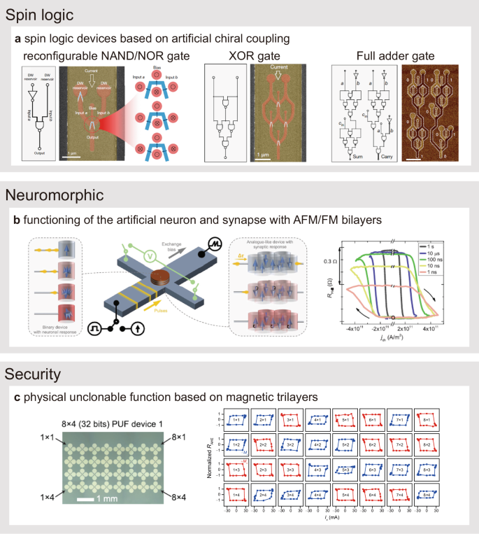
a Device structures of reconfigurable NAND/NOR, XOR and full adder gates based on artificial chiral coupled nanomagnet devices. Adopted from ref. 111. b Schematic of functioning of the artificial neuron and synapse with PrMn/[Co/Ni] devices. Adopted from ref. 124. c 32 bits security device of physical unclonable functions based on field-free SOT switching. Adopted from ref. 86.
Another SOT-based spin-logic functionality has been demonstrated, by controlling magnetization switching using various parameters such as a Bext112, a magnetization direction of coupled in-plane magnetization113, or gate voltage57,90,114. For example, spin logic devices were implemented in a Ta/CoFeB/MgO/AlOx structure by controlling the SOT switching current using the VCMA effect. In this structure, the polarity of VCMA was altered by modifying interfacial oxidation states, leading to the creation of n-type and p-type spin logics and demonstrating complementary spin logic operations90. Additionally, AND and XOR logic operations were demonstrated in a Pt/Co/AlOx structure by utilizing asymmetric gate voltage-induced field-free SOT switching and the electric control of its polarity57. These findings provide an excellent platform for scalable all-electric spin logic, paving the way for in-memory computing applications.
Neuromorphic computing applications
Another emerging non-von Neumann computing technology that utilizes SOT is neuromorphic computing, which includes spintronic-based artificial synapses and neurons. SOT devices provide analog and non–volatile memory functions within a single unit, offering more efficient artificial synapses compared to CMOS-based devices, which require complex circuitry and numerous transistors115. Various magnetic phenomena have been harnessed to create SOT-driven artificial synapses116,117,118. For example, Y. Cao et al. demonstrated multilevel characteristics and associated synaptic functionalities like excitatory postsynaptic potential (EPSP), inhibitory postsynaptic potential (IPSP), and spike-timing-dependent plasticity (STDP) by tuning the pinning potential of SOT-driven DW propagation in a Pt/Co/Ta/Co structure118. Other approaches involve controlling the Néel vector of the AFM119,120,121,122,123 or the exchange-bias direction in AFM/FM heterostructures34,124,125, where switching multiple domains creates non–volatile intermediate states (Fig. 5b). Additionally, a multilevel spintronic synaptic device was demonstrated by reversibly modulating the magnetic easy axis in a Ta/CoFeB/Pt/MgO structure with VCMA126.
SOT-driven devices can also function as artificial neurons, synchronously adjusting synaptic weights while receiving and outputting stimuli. A key characteristic of the artificial neuron is leaky integrate-and-fire (LIF) behavior, where a response occurs only when the integrated stimulus exceeds a certain threshold. SOT devices with a critical switching current can mimic the LIF function24,127,128. For example, A. Kurenkov et al. demonstrated LIF behavior in a PtMn/[Co/Ni] structure by using trains of pulses that varied in number and interval24. They also demonstrated synaptic STDP behavior in the same system, based on current pulse-driven multi-level switching.
Electronic security hardware applications
As mentioned earlier, without a Bext, a conventional SOT does not favor UP or DOWN magnetization, so it cannot deterministically switch perpendicular magnetization, but instead switches stochastically. While this random switching characteristic is detrimental to memory or logic applications, it can be utilized in other applications such as true random number generators (TRNGs), physical unclonable functions (PUFs), and probabilistic computing. The inherent randomness of the SOT switching is distinct from stochastic nano-MTJs22,129, which rely on thermal fluctuations in the magnetization direction between the two states. M.-H. Lee et al. demonstrated TRNGs based on random SOT-induced switching in NM (W, Ta, or Pt)/Nb/CoFeB structures130, where the stochasticity of SOT switching increased with Nb thickness due to the increased field-like SOT contribution.
Additionally, stochastic SOT switching behavior has been proposed for use in security hardware as PUFs86,131,132,133,134,135,136. Among these, a PUF was demonstrated that exploited field-free SOT switching in an exchange-biased IrMn/CoFeB/Ta/CoFeB magnetic trilayer structure (Fig. 5c)86. The entropy source of this PUF is the random distribution of the exchange bias direction of the IrMn/CoFeB layer, which determines the switching polarity of the perpendicular CoFeB layer. This PUF, based on the field-free SOT switching property, provides additional advantages over other spintronic PUF technologies in terms of magnetic field immunity, reconfigurability, and scalability.
Conclusion
In this Perspective, we review field-free SOT switching of perpendicular magnetization and its potential applications. There are two representative approaches for field-free SOT switching: conventional SOT with in-plane symmetry breaking, and unconventional SOT utilizing out-of-plane spin polarization. In the former, symmetry breaking methods include the use of internal effective magnetic fields such as the exchange bias field from AFM, the dipolar field from other FM layers, or DMI field. It also involves inducing spatial non-uniformity or tilted PMA along the transverse direction or creating a spin current density gradient. The latter, unconventional SOT, exploits spin current with out-of-plane spin polarization in low (magnetic) symmetry materials or magnetic trilayers.
We also discuss the potential applications of SOT technologies ranging from conventional memory and logic devices to neuromorphic computing with artificial synapses and neurons, as well as electronic security hardware such as TRNGs and PUFs. The further development of field-free SOT-MRAM with reduced switching current could revolutionize computing technologies by offering faster operating speeds, lower power consumption, and enhanced reliability.


Responses