Full-color tuning in multi-layer core-shell nanoparticles from single-wavelength excitation
Introduction
Lanthanide-based materials are a class of ideal candidates for efficient nonlinear anti-Stokes visible photon upconversion under infrared excitations1,2,3. Lanthanide ions have abundant discrete energy levels that allow for multiple emission colors in the visible spectral region4,5,6,7, showing great promise in diversities of frontier applications including laser8,9, volumetric display10,11, super-resolution nanoscopy12,13,14, and biophotonics15,16,17. However, conventional upconversion and luminescent materials usually exhibit a specific emission color when the dopants and compositions are determined. Recently, an interesting orthogonal excitation–emission phenomenon was observed in multi-layer core-shell (MLCS) nanoparticles, featuring a change in the emission colors by simply switching excitation wavelengths18. For instance, a spatial separation of Er3+ and Tm3+ into suitable layers in an MLCS nanostructure results in green light emission (from Er3+) under 980 nm irradiation and blue light emission (from Tm3+) under 808 nm irradiation19,20,21,22. As a result, the red-green-blue (RGB) colors become obtainable by integrating more luminescent layers in an MLCS nanostructure or by employing non-steady state upconversion10,23,24,25. Such extension in optical properties of luminescent materials further promotes their frontier applications in information security26,27, optical memory28, super-resolution nanoscopy29, photodynamic therapy30, and optogenetics31,32.
However, it should be noted that dual or more excitation wavelengths are necessary for the color tuning of MLCS nanoparticles, resulting in a complex design of the pumping system. Also, the MLCS structure together with its compositions and dopant species have to be exquisitely designed to avoid any spectral cross-talk between different luminescent shell layers, which raises stringent demands for the sample structure and experimental synthesis. These intrinsic constraints seriously limit the design and application of luminescent materials with a full-color switchable output by using only a single-wavelength excitation.
Recent work suggests that temporal control of upconversion dynamics provides a new possibility to tune and edit emission colors3. As a typical nonlinear anti-Stokes process3,33, it requires time to populate the emitting energy level of a lanthanide emitter from its lower-lying intermediate state, giving rise to a characteristic rise time for the resultant emission (Fig. 1a). This provides a new parameter, apart from the decay time, to describe the temporal evolution process of a photon upconversion by comparison to conventional Stokes luminescence. This feature means that a color change would be available by modulating the upconversion rise times for specific lanthanide emitters that have multiple emission peaks (Fig. 1b). On the other hand, for a given emitting state, it has an intrinsic decay time under infrared excitation. When multiple emission profiles are designed in one upconversion system, the emissions with longer decay times can be singled out by filtering out those shorter decay emissions through the time-gating technique22. Therefore, a rational combination of modulating approaches on both the initial rise and final decay processes of upconversion luminescence could be greatly capable of producing full-color switchable output from a single nanoparticle under a single-wavelength excitation.
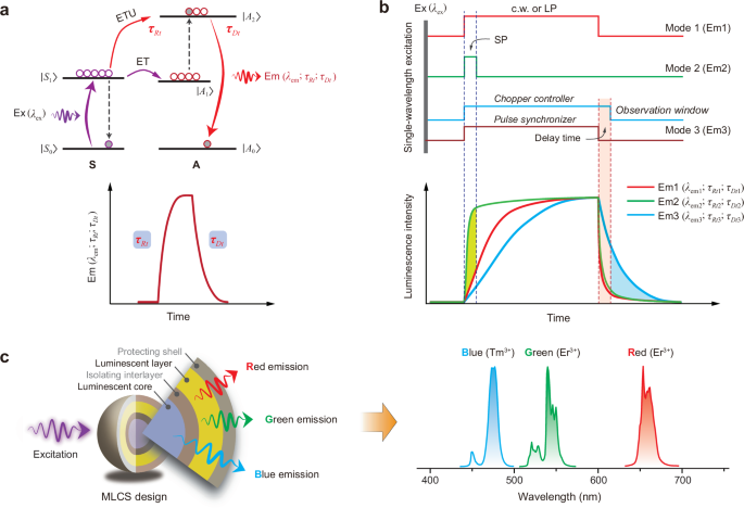
a Schematic of up-transition and decay processes in a sensitizer–actator (S-A) coupled system with characteristic rise time (τRt) and decay time (τDt) for an upconverted emission. ET, ETU, Ex, and Em stand for energy transfer, energy transfer upconversion, excitation, and emission, respectively. |A0-2> and |S0,1> stand for energy levels of S and A dopants, respectively. b Schematic of tuning RGB colors through continuous wave (c.w.) (or long pulse, LP) and short pulse (SP) excitations, and time-gating technique. The c.w. (or LP) is used for the emission with a longer rise time, SP for the emission with a shorter rise time, and time-gating for the longer decay emission. c Proposed multi-layer core-shell (MLCS) nanostructure consisting of two complementary luminescent layers for full-color tuning under a single excitation wavelength with suitable modulation modes.
Here, we describe a conceptual model to realize the full-color tuning in a single MLCS nanoparticle upon a commercial 980 nm laser (Fig. 1c). The conventional emitters of Er3+ (green and red emissions) and Tm3+ (blue emission) were selected and spatially doped into different nanoscale regions toward its specific emission colors. We find that Er3+ in shell can produce red-to-green color-switchable emissions by tuning its upconversion dynamics through the cooperative modulation effect of the Tm/Yb couple. The blue light of Tm3+ in core can be singled out by applying the time-gating technique which removes the short-decayed green and red emissions. More importantly, it is capable of simplifying the pump systems greatly by only using one single-wavelength laser excitation instead of two or more, as shown in the previous reports. We further demonstrate the new role of Tm3+ in manipulating upconversion dynamics in addition to the typical role of a blue-emitter, which plays a key role in enabling the temporal control of emission colors of Er3+. These findings help deepen the understanding of the photophysics of lanthanide ions, showing great promise in the frontier photonic applications.
Results
To validate our hypothesis, we first explore how to realize the temporal control of red/green color-switchable upconversion of Er3+. In general, its emission profile consists of two adjacent green emission bands (2H11/2,4S3/2 → 4I15/2 transitions) and a red emission band (4F9/2 → 4I15/2 transition) under the commonly used 980 nm excitation34,35,36. Note that the conventional Er3+/Yb3+ codoped materials usually show a fixed emission color, such as green for the regular NaYF4:Yb/Er@NaYF4 core-shell nanoparticles under both continuous-wave (c.w.) and pulse 980 nm laser excitations (Supplementary Fig. 1a). However, it is interesting to observe a faster rise time for the green emission than that of the red emission (Supplementary Fig. 1b). This suggests that temporal control of emission colors would be highly desirable by pre-editing the steady-state upconversion emission profiles of Er3+. Here we introduced a small amount of Tm3+ in the Er/Yb couple to mediate the upconversion dynamics of Er3+. It can promote the population of Er3+ from its 4I11/2 state to the lower-lying intermediate 4I13/2 state through an energy-transfer looping (ETL) process, namely Er3+ (4I11/2) → Tm3+ (3H5) → Er3+ (4I13/2), consequently leading to a red color output under c.w. 980 nm excitation (Fig. 2a; Supplementary Fig. 2).
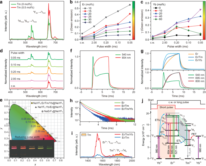
a Upconversion emission spectra of NaYF4:Er/Tm/Yb(15/0.5/40 mol%)@NaYF4 and NaYF4:Er/Yb(15/40 mol%)@NaYF4 core-shell nanoparticles under 980 nm excitation. b, c Upconversion emission intensity ratio of green emission (γ) over the total emissions obtained from the NaYF4:Yb/Er/Tm(40/10-40/0.5 mol%)@NaYF4 and NaYF4:Yb/Er/Tm(0-60/15/0.5 mol%)@NaYF4 core-shell nanoparticles under c.w. and pulse excitations. d Normalized upconversion emission spectra of NaYF4:Yb/Er/Tm(40/15/0.5 mol%)@NaYF4 core-shell nanoparticles under c.w. and pulse 980 nm excitations. e CIE (x,y) chromaticity diagram of emission colors of sample in (d). Insets show the corresponding emission photographs. f Time-dependent upconversion emission profiles of Er3+ at 540 and 654 nm for (d) sample. g Time-dependent upconversion emission profiles of Er3+ at 540 nm from NaYF4:Er(15 mol%)@NaYF4, NaYF4:Er/Yb(15/40 mol%)@NaYF4 and NaYF4:Er/Tm(15/0.5 mol%)@NaYF4 core–shell nanoparticles (top panel) and that of Er3+ at 540 nm from NaYF4:Er/Yb/Tm(15/40/0.5 mol%)@NaYF4 core-shell nanoparticles and Tm3+ at 695 and 800 nm from NaYF4:Yb/Tm(40/0.5 mol%)@NaYF4 core-shell nanoparticles (bottom panel). h Decay curves of Er3+ at its 4S3/2 state (540 nm) from NaYF4:Er(15 mol%)@NaYF4, NaYF4:Er/Tm(15/0.5 mol%)@NaYF4 and NaYF4:Er/Tm/Yb(15/0.5/40 mol%)@NaYF4 samples under pulse 980 nm excitation. i Infrared emission spectra of NaYF4:Er/Tm(15/0.5 mol%)@NaYF4 and NaYF4:Er/Tm/Yb(15/0.5/40 mol%)@NaYF4 samples under 980 nm excitation. j Schematic of possible processes for the observation of green emission color under short pulse laser excitation. CR1 and CR2 stand for [Er3+ (2H11/2); Tm3+ (3F4)] → [Er3+ (4I9/2); Tm3+ (3H4)] and [Er3+ (2H11/2); Tm3+ (3F4)] → [Er3+ (4I11/2); Tm3+ (3F2,3)], respectively.
A series of NaYF4:Er/Tm/Yb@NaYF4 core-shell nanoparticles were synthesized by a modified co-precipitation method (Supplementary Note 1)26, showing sphere-like morphology and hexagonal phase (Supplementary Fig. 3). The inert NaYF4 shell layer was used to prevent the lanthanide emitters in core from being quenched by surface quenchers. The upconversion emission colors are closely dependent on the concentrations of each lanthanide dopant (Fig. 2a–c), and the doping of 15Er:0.5Tm:40Yb (mol%) results in an emission color change by only modulating the pulse width of 980 nm excitation laser (Fig. 2d, e; Supplementary Figs. 4–10 and Supplementary Tables 1–4). Namely, the sample shows red color under c.w. or long pulse (e.g., >8 ms for pulse width) 980 nm excitation; while it starts to present a gradual emission color change from red to orange, yellow and green with reducing the excitation pulse width down to 0.05 ms. As a control, other excitation wavelengths (e.g., 808 or 1530 nm) do not lead to an emission color change (Supplementary Fig. 11a, b). The recently reported NaErF4@NaYF4 core-shell nanoparticles only show a red color under both c.w. and pulse 980 nm excitation (Supplementary Fig. 11c, d)37,38,39. In addition, the steady-state red upconversion of the Er/Tm/Yb tri-doped sample is much greater than that of the Yb/Ho/Ce tri-doped system (Supplementary Fig. 12). These observations confirm the feasibility of achieving emission color tuning of Er3+ through temporal control of its upconversion dynamics under conventional 980 nm excitation, laying a solid foundation for the following full-color tuning with a single wavelength excitation.
To shed more light on the upconversion mechanism of Er3+ in the Er/Tm/Yb tri-doped system, we measured the time-dependent upconversion emission profiles of the samples. As shown in Fig. 2f, it is interesting to observe a faster rise time for the green emission than the red emission during the excitation pulse width. This feature ensures the observation of green emission color by simply reducing the excitation laser pulse width. The faster rise time of green emission than that of red emission can originate from the difference in their upconversion processes. The green upconversion is based on the resonant energy transfer from Yb3+ (at its 2F5/2 state) to Er3+ (at its intermediate 4I11/2 state) followed by an up-transition process3. In contrast, for the red upconversion its intermediate 4I13/2 state has to be pre-populated through a Tm3+-mediated ETL process and/or multi-phonon relaxation (MPR) from 4I11/2 to 4I13/2 (Supplementary Fig. 2b). Such additional processes result in a temporal delay in the up-transition of Er3+ to the red emitting 4F9/2 state. Although the presence of Tm3+ accelerates the rise time of red emission, it is still slower than that of the green emission (Fig. 2f; Supplementary Fig. 13).
Another interesting observation in Fig. 2f is the abrupt drop in the time-dependent emission profile of Er3+ when the pulse duration is over ~0.5 ms. This suggests that some relatively slow depleting processes begin to occur at the green emitting levels. To shed more light on this issue, we prepared a set of core–shell control samples with single doping of Er (15 mol%), and codoping of Er/Tm (15/0.5 mol%) and Er/Yb (15/40 mol%) in the core (Supplementary Fig. 14). Their time-dependent emission profiles were compared in Fig. 2g (top panel), showing no abrupt drop for all of them. Thus the abrupt decline of Er3+ should result from the cooperative modulation effect due to the presence of both Tm3+ and Yb3+, which work together to make a dynamic manipulation of Er3+ upconversion. Importantly, it was found that the lifetime of green emission exhibits a decrease for the Er-doped control samples after the presence of Tm3+ or Tm/Yb couple (Fig. 2h). The abrupt decline is presumably attributed to the cross-relaxation (CR) between Er3+ at its green emitting 2H11/2,4S3/2 states and Tm3+ at its intermediate 3F4 state instead of the ground state 3H6. Taking into account a small energy mismatch (~1600 cm−1) 3, the energy transfer from Yb3+ (at its 2F5/2 state) to Tm3+ (at its 3H5 state) needs more time than that to Er3+ (at its 4I11/2 state), which is a resonant process. As a result, the CR occurring at the 3F4 state of Tm3+, populated by a rapid MPR process from the upper-lying 3H5 state, would have a slower temporal feature. In this case, the upconversion emission based on the intermediate 3F4 state of Tm3+ should also have a slower rise time than that of Er3+ (Supplementary Fig. 15). This was confirmed by the time-dependent upconversion emission profiles of Tm3+ (e.g., 695 and 800 nm emissions) upon 980 nm excitation (Fig. 2g bottom panel). For the Er/Tm (15/0.5 mol%) coupled control sample, much less Tm3+ ions populate at its 3F4 state, which cannot support efficient CR processes, and there is no change in the emission color with tuning the pulse width of excitation laser (Supplementary Fig. 7a). While after the presence of Yb3+, much more Tm3+ ions were pumped in its 3F4 state followed by the energy transfer from Yb3+ (2F5/2) to Tm3+ (3H5) and subsequent relaxation to its 3F4 state, as evidenced by the remarkable enhancement of infrared emission of Tm3+ from its 3F4 → 3H6 transition (Fig. 2i). In contrast, no obvious abrupt decline was observed in the Er/Yb codoped control sample, implying that the CR between Er3+ and Yb3+ has no notable contribution to the color change despite a decline in the lifetime of green emission (Supplementary Fig. 16)40,41,42. The observation of temporal abruptness was also in agreement with the simulation through rate equations via an upconversion model (Supplementary Fig. 17; Supplementary Note 2). Thus, we have demonstrated the key role of the Tm/Yb couple in manipulating both the rise and decay dynamics of Er3+, and the involved processes were schematically illustrated in Fig. 2j.
We next investigate how to realize the long-decay blue emission light together with a slower rise time than that of green and red emissions of Er3+. This is a prerequisite to single out the blue emission from the total upconversion emission profiles through the time-gating technique. Among a series of lanthanide ions, Tm3+ is a possible candidate for blue emission light by taking advantage of its 1G4 → 3H6 transition (peaking at around 475 nm), which is widely observable in Yb3+/Tm3+ codoped systems upon 980 nm excitation (Fig. 3a) 4. However, a crucial issue for Tm3+ lies in the serious concentration quenching effect when it is doped into host with higher concentrations due to the multiple CR processes43,44,45, such as [1G4; 3H6] → [3H4; 3H5], which would result in a rapid decline in the lifetime of Tm3+ at its 1G4 state in addition to decreased blue emission intensity (Fig. 3b, c). Other emission levels of Tm3+ show a similar result (Supplementary Fig. 18a). To get rid of this limit, we attempt to enlarge the ionic separation by employing a smaller Tm3+ dopant content, and the CR processes occurring in the blue emitting level were well suppressed, resulting in markedly prolonged lifetime (Fig. 3c). Also, it can be observed that a decrease of Tm3+ content helps to slow the rise time of blue emission (Fig. 3d), might be resulted from a greater Tm3+-Yb3+ ionic separation. This is a key point to remove the interference of blue emission on other emissions under short pulse 980 nm excitation. Relatively low doping of Yb3+ content is also helpful for intense blue emission with slower rise time and longer decay time (Fig. 3e; Supplementary Fig. 18b). Thus, the Yb/Tm couple with the concentration ratio of 20/0.1 mol% was selected for the on-demand blue emission light.
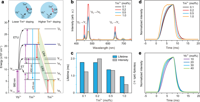
a Schematic of blue upconversion of Tm3+ in Yb/Tm coupled system and possible CR processes that may result in quenching of the emissions. CR3 and CR4 stand for CR processes of [1G4; 3H6] → [3F2; 3F4] and [1D2; 3H6] → [1G4; 3F4], respectively. Insets compare the ionic interactions with and without CR for lower and higher Tm3+ dopant cases. b Upconversion emission spectra of NaYF4:Yb/Tm(20/0.1-1.0 mol%)@NaYF4 core-shell nanoparticles under 980 nm excitation. c Dependence of 475 nm emission intensity and lifetime on Tm3+ dopant concentration for (b) samples. d, e Time-dependent upconversion emission profiles of Tm3+ at 475 nm from (b) samples and NaYF4:Yb/Tm(10-40/0.1 mol%)@NaYF4 core–shell nanoparticles upon pulse 980 nm excitation with a pulse width of 8 ms.
To achieve the single-wavelength responsive full-color output in a single nanoparticle, we construct an MLCS nanostructure to integrate each functional unit. In detail, the Yb/Tm couple was codoped into the core and Er/Tm/Yb into the outer luminescent shell layer, both of which were spatially separated by growing an optically inert NaYF4 epitaxial interlayer aiming to avoid any spectral cross-talk between them26, and finally another NaYF4 shell was coated outside to prevent surface quenching effect46. In such a design, a newly emerging issue encountered is that the blue emission from the core was concurrently activated along with the red emission upon c.w. 980 nm excitation (Supplementary Fig. 19; Supplementary Table 5). This means that the content of 40 mol% Yb3+ in the luminescent shell layer is not sufficient enough to block the 980 excitation photons reaching the blue light emitting core21,47. In this case, we attempted to use the Yb sublattice to raise Yb3+ content in the luminescent shell layer, some of which could act as the energy harvester to facilitate the trapping of incident 980 nm excitation photons and properly minimize the excitation energy to activate Tm3+ in the core (Fig. 4a, b; Supplementary Fig. 20), resulting in observation of red color output under c.w. 980 nm excitation. Also, it is still capable of enabling green emission light under short pulse 980 nm excitation due to the faster rise time of the green emission. More importantly, the lifetime of Tm3+ emission is much longer than that of Er3+ (Fig. 4c), which allows for the blue emission light output through the time-gating technique to filter out those short-decay emissions (Supplementary Note 3), resulting in RGB color-tunable emissions under suitable excitation modes (Fig. 4d). The RGB colors can be kept in a large range of pump power densities under 980 nm excitation (Supplementary Fig. 21; Supplementary Tables 6–8). We further examined the role of the inert NaYF4 interlayer between the core and luminescent shell (Supplementary Fig. 22) and found that it is indispensable for the observation of the blue emission by suppressing the interfacial quenching effect (Supplementary Figs. 23–26). In comparison, the thickness of the outermost NaYF4 shell has a slight effect on the color tuning besides a change in the luminescence intensity (Supplementary Figs. 27–31). So far, we have successfully realized the RGB colors output in an MLCS nanoparticle by simply tuning the excitation modes of a single 980 nm laser (Fig. 4e) for the first time to the best of our knowledge (Supplementary Table 9).
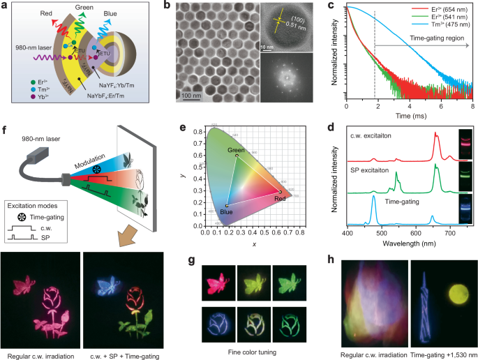
a, b Schematic of the NaYF4:Yb/Tm(20/0.1 mol%)@NaYF4@NaYbF4:Er/Tm(15/0.5 mol%)@NaYF4 MLCS sample and corresponding TEM image, high-resolution TEM image and Fourier transform diffraction pattern. c Decay curves of the upconverted red, green, and blue emissions from (b) sample under pulse 980 nm excitation. d, e Upconversion emission spectra of (b) sample under 980 nm excitation with modes of c.w., short pulse, and time-gating technique, respectively. f Schematic of the full-color volumetric display using the (b) sample by simply altering the excitation modes. The pattern (A butterfly fluttering over a rose) shows a blue butterfly, a red rose, and green leaves under suitable excitation mode. As a control, it shows only red color under regular c.w. 980 nm excitation. g Fine color tuning through modulating the excitation laser modes. h Identification of concealed information (Canton tower facing the moon) through tuning excitation modes. The concealed information pattern was painted using (b) sample, and the interference information using NaYF4:Yb/Er/Tm(40/2/0.25 mol%)@NaYF4, NaYF4:Yb/Tm(30/1.5 mol%)@NaYF4, and NaYF4:Yb/Ho/Ce(20/2/16 mol%)@NaYF4 core–shell nanoparticles.
The realization of primary RGB color-switchable emissions permits new chances for frontier photonic applications. As a proof of concept, we prepared a painting of a “butterfly-over-rose” pattern using such nanoparticles through the screen printing method (Fig. 4f top). Interestingly, it can precisely show a red rose flower under c.w. 980 nm irradiation, green leaves, and bud under short pulse 980 nm irradiation, and then blue butterfly under the time-gating mode (Fig. 4f; bottom right panel). In contrast, under regular c.w. 980 irradiation the entire painting only shows a single red color (Fig. 4f; bottom left panel). More colors can be easily achievable by fine-tuning the pulse widths of the incident laser (Fig. 4g). This may contribute to the full-color volumetric display under a single excitation wavelength and reduce the complexity of pump systems18. As an added benefit, such smart control of emission light colors also holds great promise in multi-level anti-counterfeiting26. The concealed information can be clearly distinguished by applying a time-gating technique and 1530 nm irradiation (Fig. 4h; Supplementary Fig. 32).
Discussion
We have demonstrated a new conceptual model that is convenient to realize the full-color tuning from a single nanoparticle upon a single 980 nm wavelength excitation. The temporal control of up-transition and decay dynamics is confirmed to be a facile but effective strategy to achieve color-switchable output from conventional lanthanide emitters of Er3+ and Tm3+. Intriguingly, the new roles of lanthanide ions were discovered during the manipulation of luminescence dynamics and energy transport over the lanthanide sublattice, which helps break the stereotypes of each lanthanide ion. The results described in this work contribute to the design of full-color emissive nanoparticles for volumetric display, which would be further promoted by the new strategies of full-color tuning and device miniaturization in the future. Moreover, in light of versatile color-tunable properties, they would also help develop a new class of smart materials for frontier applications such as information security and storage, functional flexible devices, and wavelength-tunable lasers.
Methods
Materials
The materials including erbium (III) acetate hydrate (99.9%), ytterbium (III) acetate hydrate (99.99%), thulium (III) acetate hydrate (99.9%), yttrium (III) acetate hydrate (99.9%), holmium (III) acetate hydrate (99.9%), cerium (III) acetate hydrate (99.99%), oleic acid (90%), 1-octadecene (90%), sodium hydroxide (NaOH; >98%), and ammonium fluoride (NH4F; >98%) were all purchased from Sigma-Aldrich and used as received unless otherwise noted.
Synthesis of nanoparticles
The core and core-shell nanoparticles were synthesized using a modified co-precipitation method. The MLCS nanoparticles were prepared by combining coprecipitation and thermal decomposition methods. The synthetic procedures for other control nanoparticles were identical to the above methods except for the use of different core seed nanoparticles and corresponding lanthanide shell precursors. The experimental details are provided in the Supplementary Information.
Characterization
The low- and high-resolution transmission electron microscopy measurements together with energy-dispersive X-ray spectroscopy were carried out on a JEOL JEM-2100F transmission electron microscope (200 kV). Powder X-ray diffraction was performed by a Philips Model PW1830 X-ray powder diffractometer with Cu Kα radiation (λ = 1.5406 Å). The upconversion emission and infrared emission spectra were recorded by a Zolix spectrofluorometer equipped with external power-controllable laser diodes of 980, 808, and 1530 nm. The decay curves were measured using the same spectrofluorometer through using the pulse laser as an excitation sources. The lifetime values were determined by fitting the decay curves by the equation: I = I0exp(-t/τ), where I0 is the initial emission intensity at t = 0 and τ is the lifetime. The upconverting emission photographs were taken by a digital camera with suitable optical filters. All the measurements were conducted at room temperature. The time-gating observation is obtained based on the setup in which a chopper and a pulse synchronizer were used to set the delay time, and the details are provided in the Supplementary Information.
Reporting summary
Further information on research design is available in the Nature Portfolio Reporting Summary linked to this article.
Responses