Full textile-based body-coupled electrical stimulation for wireless, battery-free, and wearable bioelectronics

Introduction
Electrical stimulation has been used worldwide as a promising nonpharmacological treatment for long-term therapy and functional recovery of tissues1,2. Electrical stimulation is clinically approved for treating various neurological diseases, including Parkinson’s disease, epilepsy, and depression3,4,5,6,7, and has shown significant effects on tissue regeneration, such as bone repair8 and wound healing9,10,11, as well as on inducing muscle fiber vitalization in functional electrical stimulation12,13. In recent years, technologies that utilize bioelectronic devices capable of electrical stimulation for gastrointestinal stimulation have been developed to aid in weight management14,15,16 or to replace the pacemaker function in the heart17. Despite recent advances in micro-batteries, ongoing challenges remain, including toxicity and replacement issues, necessitating improvements in energy supply methods to provide more convenient and effective electrical stimulation. Recently, energy-harvesting technologies have been proposed for converting waste energy from the human body into energy for electrical stimulation10,18,19,20. However, the spatial constraints for generator installation and the need for wire connections between the stimulation site and the power source remain challenging.
To address these issues, new approaches have been proposed that use the human body as a medium for wireless energy transfer. Ultrasound can vibrate generators implanted within biological tissues to produce electrical energy21,22. The body-coupling effect allows electromagnetic waves to be transmitted through the human body to power small electronic devices23,24. However, ultrasound produces mechanical vibrations and high-frequency electromagnetic waves can cause dielectric losses25 in biological tissues and convert energy into heat. This leads to energy loss with distance, and restricts the positioning of the energy source and stimulation site. Extremely low-frequency (ELF) electromagnetic waves under 1 kHz can be transmitted regardless of the distance within the body26 without causing dielectric losses in biological tissues consisting of cytoplasm, extracellular fluid, and ions, allowing energy transfer unaffected by distance. However, they require generators, batteries, additional circuits, devices, and PCB substrates for electrical stimulation.
We recently reported a novel concept involving concentrating an electric field at any desired location on the body to induce wireless electrical stimulation, thereby eliminating the need for energy harvesters or batteries26,27,28. This approach is based on the potential distortion that occurs when energy is transferred via the body-coupled effect and spatial structure of the electrodes (Fig. 1a). This strategy is called body-coupled electrical stimulation (BCES) because it enables wireless electrical stimulation by transmitting energy through body coupling, also known as body-mediated energy transfer29,30,31,32, human body communication33,34, and body area networks35. The utilized energy loss occurs from the electromagnetic waves from electronic devices or static electricity (triboelectrification) generated during physical activity32,36. The transmitted energy extends towards the body parts in contact with other objects of different potentials, such as the ground, forming a potential distribution across the body (Fig. 1b). If a passive electrode is attached to the body and a counter electrode with a different potential is connected, electrons move to balance the electrical potential between them, distorting the potential and creating a localized electric field in the biological tissues (Fig. 1c).

a Extremely low frequency (ELF) electric fields below 1 kHz are transmitted towards the human body when it comes into contact with objects of different potentials (earth ground). Electrical stimulation is achieved by inducing potential distortion during this body-coupled energy transfer. b Ψ1 and Ψ2 represent the potentials of muscle and skin, respectively. ELF electric fields generate potential distributions based on the direction of transmission, but the high permittivity of biological tissues results in minimal potential reduction and almost no potential difference between the muscle and skin. c When a passive electrode attached to the body is connected to a counter electrode with a different potential, electron movement causes potential distortion (ΨD). This potential distortion creates a potential difference between the muscle and the outer skin, inducing a localized electric field. d Fully textile-knitted polyester and conductive threads. e The passive electrode pattern is located at the contact area with the body, and the counter electrode is positioned in the area not in contact with the body. f Photo of wearing BCES socks. g Changes in the BCES socks’ passive electrode resistance with respect to strain. h Resistance changes when washed BCES socks are dried.
In this study, we aimed to minimize the need for additional circuits and devices by focusing on the development of fully textile-based electrical stimulation clothing. Previous research introduced the concept of BCES and tested its clinical effects in a mimicked structure; however, crucial capabilities for commercial applications have not yet been validated. First, we confirmed the feasibility of weaving conductive fibers with polyester fibers into socks to ensure the stability of the textile-based stimulation bioelectronics. Subsequently, we focused on verifying the design factors and performance of the pattern in the BCES socks through computational modeling and clinical measurements. Finally, we evaluated the effects of stimulating the calf muscles with BCES during exercise on exercise performance and muscle fatigue. Our findings demonstrate the functionality of the complete textile-type BCES and its capability to induce activation in human muscle tissue and modulate exercise performance.
Results
Feasibility validation in commercial BCES socks
To fully implement textile-type BCES clothing, we utilized a commercial automatic sock-knitting machine provided by Barun Bio Inc. to knit BCES socks. Multiple needles and hooks were used to arrange the textiles by interlocking. A combination of commercial polyester and conductive threads was used to pattern the passive electrodes at the contact points between the sock and calf muscles (Fig. 1d). The counter electrode was patterned on the outside of the sock, which did not come in contact with the body, and was knitted to connect it with the passive electrodes (Fig. 1e and Supplementary Fig. 1). The conductive thread is silver-coated nylon (silver filament DTY 140D, SuZhou TEK Silver Fiber Technology Co.,Ltd), commonly used in sportswear, and has a mechanical strength and behavior similar to that of a regular thread. Therefore, when knitted into textiles, they stretch and crumple, similar to ordinary clothing. Being completely implemented in textile form, the BCES socks could be worn comfortably, similar to regular socks (Fig. 1f). The knitted conductive fibers retained a loop pattern; therefore, even if the textile itself was stretched, the elongation strain of the fiber was minimal. This is similar to stretchable electrodes patterned in loop form in typical flexible electronics37,38. Even when the cuff of the BCES sock is stretched by 100%, the resistance shows a small change of approximately 2.4 Ω (Fig. 1g and Supplementary Fig. 2). To verify the stability against sweat and washing, the change in resistance was measured by drying the washed socks for 5 min. The change of resistance due to washing or water absorption was very small, approximately 1.1 Ω, demonstrating the excellent performance and commercial feasibility of the BCES socks (Fig. 1h). However, when the wet BCES socks were worn, we observed that the electric field strength decreased significantly, reaching as low as 91.56 mV/mm (Supplementary Fig. 3b). Despite the minimal change in resistance when wet, the substantial decrease in electric field can be attributed to the water in the BCES socks wetting the skin, which interferes with the contact between the skin and the passive electrode of the BCES design. The presence of water affects the electric field concentration effect by altering the interface between the electrode and skin, thereby reducing the efficiency of electric field concentration. As the BCES socks dried, the electric field strength recovered to its original level, demonstrating that the BCES socks can regain their functionality once they are dried. Furthermore, to evaluate the washability of the BCES socks, we conducted repeated washing tests. The socks were laundered according to standard washing procedures for 0, 10 and 20 cycles (Supplementary Fig. 3a, c). After each set of washing cycles, we performed visual inspections and measured the electric field generated by the BCES design. The visual inspections revealed no significant changes in the appearance of the BCES design—the conductive threads remained intact without fraying or degradation. Moreover, the measurements indicated that the electric field strength remained consistent after washing, demonstrating that the electrical performance of the BCES socks was maintained even after multiple washes. These results confirm the excellent washability and durability of the BCES socks, highlighting their suitability for regular use in practical applications.
Input and output systems of BCES
BCES utilizes energy loss from electronic devices and static electricity (triboelectrification) generated from physical activities as its power source, eliminating the need for an external power supply or generator (Fig. 2a). These energy losses, which have an ELF range, allow energy transfer across the human body while minimizing the dielectric loss. In electronics, a loss potential with a frequency of 50−60 Hz occurs and is mainly generated by plugged-in electronics (Fig. 2b). The magnitude of this energy varies between 10−200 V depending on the device, such as charging smartphones, laptops, hair dryers, and other household electronics (Supplementary Fig. 4). Interestingly, AC signals are detected even in devices driven by DC power. This phenomenon is attributed to unused AC energy coupling through the device casing and internal wiring. Our previous research demonstrated that this energy was dissipated by polarizing surrounding materials but could be converted into usable electrical energy without increasing the power consumption of electronics32. Although further discussion is required regarding these energy losses, they represent a completely wasted energy source that can be harnessed as a stable and powerful energy source. Additionally, static electricity generated from repetitive physical activities, such as walking or friction from clothing, results in non-sinusoidal ELF electrical energy losses. Energy losses from physical activity do not exceed 6 Hz because the static electricity is correlated with the repetitive movements of the body, which can be easily transmitted through the body and converted into usable electrical energy, as reported in several studies32,36.
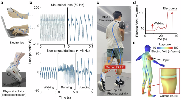
a Energy losses utilized as energy sources: electromagnetic waves emitted from electronics and static electricity (triboelectrification) generated from physical activities. b Energy losses from electronics (laptop) and physical activities have frequencies of 60 Hz and below 6 Hz, respectively. While the magnitude of the loss potential of input can vary depending on the devices or type of physical activity, the frequency remains below ELF, allowing easy transmission through the human body. c BCES can utilize energy from electronic devices and physical activities either independently or simultaneously as input sources. d Electric fields measured in BCES: physical activities generate irregular electric fields of over 10 mV/mm, whereas electronics generate stable electric fields of over 100 mV/mm. e 3D simulation of BCES. When a 100 V, 60 Hz input source is applied to the right arm, electric field concentration is achieved along the passive electrode pattern.
BCES socks use these two types of energy losses as input sources, which can be utilized independently or simultaneously (Fig. 2c). The electric field formed by the BCES socks was measured in root mean square (RMS) values using a handheld multimeter and a non-grounded method39. Typical grounded benchtop equipment can overestimate the electric field strength because of its grounding40,41, making it unsuitable for measuring electric fields on the human body. When walking with the BCES socks, an electric field of over 10 mV/mm was concentrated owing to static electricity (Fig. 2d). This field, formed by body movements, is irregular because it is non-sinusoidal. A strong and stable electric field of over 100 mV/mm was generated when the hand was placed on a laptop while wearing the BCES socks. This 60 Hz sinusoidal energy loss resulted in a relatively large and stable electrical stimulation. In the case of electrical stimulation, it is generally reported that exceeding a certain threshold can activate cells or tissues2, and the range of electric fields (approximately 10–100 mV/mm) generated by BCES covers the range necessary to activate muscle cells42,43. The BCES can also be calculated using finite element analysis (COMSOL Multiphysics). When a sinusoidal energy loss of 60 Hz and 100 V were applied to the right arm, an electric field greater than 100 mV/mm was generated at the passive electrode (Fig. 2e). In this simulation, the passive and counter electrodes were grouped as floating electrodes, meaning that they were not grounded but connected as a single electrode. This proves that BCES can be implemented solely through the structural pattern of the electrodes.
Experimental and computational analysis of design factors
The parameters of the BCES design that influenced the concentration of the electric field were identified, and the COMSOL simulation results were compared and analyzed with the experimental results. Figure 3a shows the experimental setup employing a laptop generating a loss potential of 180 V at 60 Hz as the input source. An aluminum tape, serving as the passive electrode of the BCES design, and a wire, functioning as the measurement electrode to assess the skin electric field, were affixed to the left calf at 1 mm interval. The skin electric field and induced voltage were measured using two multimeters: one connecting the measurement electrode to the passive electrode and the other connecting the counter electrode (a 2 cm × 2.5 cm piece of aluminum tape) to the passive electrode. As depicted in Fig. 3b, the parameters studied included the lengths of the passive electrode and counter electrode, as well as a horizontal gap (distance) and a vertical gap (height) between the passive electrode and counter electrode. Initially set at 15 mm for passive electrode thickness, 2.5 cm for counter electrode length, 0.5 cm for distance, and 0 cm for height, these parameters were adjusted by increasing the height, distance, and counter electrode length in 5 cm steps, and passive electrode thickness in 5 mm steps. We first investigated the effect of different passive electrode geometries, such as sine wave, ramp wave, and straight line, on the electric field strength. COMSOL simulations indicated that sine wave and ramp wave shapes can generate higher electric field strength in a localized region due to their sharper geometry (Supplementary Fig. 5a, b). However, when the electric field was measured 1 mm above the electrode edge by COMSOL simulations and experimental measurements, similar field strengths were observed for all shapes (Supplementary Fig. 5c). Therefore, we standardized the passive electrode to a straight shape for experiments investigating other variables.
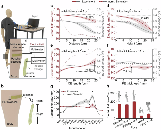
a Schematic of the BCES experimental setup. b Schematic of BCES with the main components. The electric field and induced voltage of BCES as a function of (c) distance and d height between the passive electrode (PE) and counter electrode (CE), e length of CE, f thickness of PE. The electric field of BCES with respect to (g) input location and h user poses.
Figure 3c, d display the variations in the electric field concentration and induced voltage based on the distance and height between the passive and counter electrodes, respectively. In Fig. 3c, both the experimental (solid line) and normalized simulation (dotted line) results indicate a clear reduction in the electric field strength as the distance increases. With an increase in distance to 25 cm from an initial 0.5 cm, the electric field strength decreased by 6.48% from 170.08 mV/mm to 159.06 mV/mm, and a similar trend was observed for the induced voltage. Similarly, the experimental and simulation results depicted in Fig. 3d demonstrate a reduction in electric field strength as the height increased, with a significant decrease of over 13% from 168.73 mV/mm to 143.41 mV/mm when the height was extended to 25 cm, indicating that height has a greater impact on reducing electric field strength than distance. This decrease in the electric field strength is attributed to a reduction in capacitance and less effective charge storage as the gap between the electrodes widens, which can be explained by the following capacitance formula:
where (C) is the capacitance, (varepsilon) is the permittivity of the medium between the electrodes, (A) is the effective area of the electrodes facing each other, and (d) is the distance between the electrodes.
Figure 3e, f presents the influence of the passive and counter electrode areas, respectively, on the electric field strength and induced voltage. Both figures illustrate that expanding the electrode area resulted in a marginal change in the induced voltage and an increase in the electric field strength. An optimal electric field strength for passive electrode was observed after an increase beyond 5 mm from the initial thickness (15 mm), whereas for counter electrode, the electric field strength continuously increased with length. This improvement was due to an increase in capacitance, which resulted from the larger effective area between the electrodes, thus enhancing charge storage. In conclusion, narrower gaps between the passive and counter electrodes, longer counter electrode lengths, and a passive electrode thickness of 20 mm or more enhanced the BCES performance. Additionally, regardless of the BCES design, the location of the input and the pose of the user significantly affect the electric field strength. As shown in Fig. 3g, the simulation results indicated an increase in the electric field strength when the input was near the left calf in the standing position, whereas the experimental results suggested that the input location did not significantly affect the BCES, showing relatively uniform electric field strengths across various input locations and a small yet higher field strength when the input was at the foot, contrary to the simulation results of nearly zero. However, the user poses significantly affected BCES, as shown in Fig. 3h. The electric field strength was not notably different when the right foot was raised (163.59 mV/mm), but when the left foot was raised, reducing the grounding effect of the left foot and increasing the floating ground effect of BCES, the electric field strength increased by approximately 18% to 199.78 mV/mm. In contrast, sitting or lying down reduces the electric field strength by over 70% owing to an expanded contact area with the ground, which serves as the grounding for the human body.
Validation of electric field concentration in daily life
Based on the outcomes of the preceding parameter experiments, the effect of electric field concentration in daily life environments was validated using socks equipped with an optimized BCES design (Fig. 4a). The input sources are the energy lost from electronics (Input 1) and triboelectric energy generated through physical activity (Input 2). The electric field was measured for each input, independently and in combination. Input 1 exhibits a loss potential that varies with the type of electronic device and maintains a consistent frequency of 60 Hz (Supplementary Fig. 4). Conversely, the potential of Input 2 varies depending on the material of the ground and shoe soles, with frequency changes corresponding to the speed of walking or running. As shown in Fig. 4b, a weak electric field is created by the electrical noise that occurs in daily life, even when stationary and without any inputs. During physical activity (walking), a non-sinusoidal loss potential was produced as input 2, creating an irregular electric field around the AE. In scenarios where a charging cell phone served as Input 1, a stable and intense electric field exceeding 100 mV/mm was established owing to the sinusoidal loss potential of 150 V (60 Hz) emitted by the phone. Walking while holding a cell phone (Input 1 + 2) results in the overlap of loss potentials from both inputs, generating an irregular electric field larger than that from Input 1 alone. Since the BCES socks generate these electric fields equally even when worn on both sides, the electric stimulation effect can occur simultaneously in both areas. We compared the electric fields generated when wearing BCES socks on one leg versus wearing them on both legs (Supplementary Fig. 6). Both simulation and experimental results demonstrated that the electric fields were formed similarly in each case, indicating that the BCES design can effectively stimulate multiple muscles concurrently without compromising performance at any single site. This occurs because the BCES system operates by distorting the body’s electrical potential to create localized electric fields at the sites of the passive electrodes. Each BCES sock induces a local electric field independently by altering the natural potential distribution, rather than sharing or dividing a fixed amount of energy. Consequently, adding more electrodes in different locations does not diminish the electric field strength at any one site, allowing for effective simultaneous stimulation of multiple muscles. Furthermore, the strength of the electric field varied depending on the ground and shoe type (Fig. 4c). Epoxy, commonly used on building floors; polyurethane, typical in basketball and running courts; and grass fields produce similar electric fields (Supplementary Fig. 7). The surfaces covered with PTFE tape yielded electric fields that were three times higher than those of the other ground types during physical activity. Independent of the shoe type, a comparable electric field was generated, which doubled when the socks were worn without shoes. These findings demonstrate that the passive and counter electrodes of the BCES design, implemented using conductive threads, perform equivalently to metal electrodes, enabling wireless, battery-free electrical stimulation through clothing. Additionally, if the shoe sole is coated with a highly negative material from a triboelectric series, such as PTFE, or a highly positive material, such as nylon, the electrical stimulation effect is amplified by a stronger electric field concentration during walking or running.
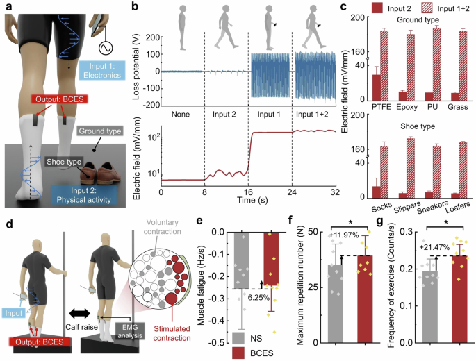
a Schematic of input conditions for BCES. b Loss potential with respect to input conditions and electric field of BCES socks. c Electric field of BCES socks with respect to ground and shoe type. d Schematic of a human testing experiment setup for determining the muscle fatigue reduction effect of BCES socks. Data analysis graphs (NS: Non-stimulation): e reduction rate of the average slope of median frequency (muscle fatigue) for analyzed participants, f increasing rate of the maximum repetition number of calf raise, and g increasing rate of the average frequency of calf raise.
Probing the physiological effect of BCES socks
Experiments were conducted to prove the effectiveness of BCES on exercise performance and muscle fatigue during calf-raises (Fig. 4d). We hypothesized about the effect of the BCES in these two aspects: First, BCES can reduce muscle fatigue; Second, if the BCES socks reduces muscle fatigue, the repetition count and the frequency of the calf raise may increase. To validate these two hypotheses, each participant performed a one-leg calf raises with their preferred leg at a self-paced speed until it could not be performed. The detailed protocol and hypotheses of the clinical trials and statistical analysis methods are described in the Functional Testing in Human Response and Statistical Analysis of the EXPERIMENTAL METHODS sections, respectively. The median frequency of electromyography signals decreases as muscle fatigue accumulates44,45. Therefore, we quantified muscle fatigue by analyzing changes in the slope of the median frequency using surface electromyography sensors (sEMG). Regarding the first hypothesis, five participants showed a reduction in the slope of the trend line (Fig. 4e). Compared to the non-stimulation (NS) socks condition, the average value of the slope of the BCES socks condition was reduced by 6.25% from −0.256 ± 0.191 to −0.240 ± 0.123 (mean ± standard deviation; p value = 0.878). For the second hypothesis, compared to the NS socks condition, the average value of the repetition count of calf raise with the BCES socks was significantly increased by 11.97% from 35.10 ± 9.48 to 39.30 ± 9.03 (mean ± standard deviation; p value = 0.045) (Fig. 4f). The operation time with the BCES socks was reduced by 5.39% from 180.00 ± 48.77 to 170.30 ± 39.26 (mean ± standard deviation; p-value = 0.437), but there was no significance. The calf-raise frequency with the BCES socks was significantly increased by 21.47% from 0.194 ± 0.035 to 0.235 ± 0.033 (mean ± standard deviation; p-value = 0.019) (Fig. 4g and Supplementary Fig. 8). Regarding the second hypothesis, five participants showed a reduction in the slope of the trend line (Supplementary Fig. 9). Clinical trials demonstrated the effectiveness of BCES socks in enhancing exercise performance and reducing muscle fatigue. The experimental results showed the possibility of reducing calf muscle fatigue during calf raise using BCES socks. Based on the experiments, we verified the following hypotheses: First, BCES socks can reduce muscle fatigue; Second, if the BCES socks reduce muscle fatigue, the repetition count and calf-raise frequency may increase. From the point of view of the first hypothesis, the average slope was reduced by 6.25% in the BCES socks condition compared with the NS socks condition. However, only five participants experienced a reduction in the slope of the median frequency, and there was no statistical difference between the BCES socks and NS socks conditions. From the point of view of the second hypothesis, the average value of the repetition count and frequency of calf raise significantly increased by 11.97% (p value = 0.045) and 21.47% (p value = 0.019) for the BCES socks condition compared with the NS socks condition. Based on these results, we can expect that BCES socks can reduce fatigue of the gastrocnemius muscle during calf-raising. Because we verified that the BCES socks can improve the repetition count and calf-raise frequency, we believe that the effect of the BCES socks is not only on quasi-static motion, but also on more dynamic locomotion.
There was no significant difference in the average slope between the BCES socks and NS socks condition because the result of the average slope was influenced by the design of the experimental protocol for human testing. Compared with the typical experimental protocol that revealed the effect of the wearable system on muscle fatigue, our experimental protocol had different points at the experimental constraint. In the typical protocol, they imposed constraints such as the frequency of motion performed using a metronome, experiment time, and repetition count of motion. However, in this study, we did not impose constraints on the participants regarding motion frequency, experiment time, or repetition counts. Owing to the absence of these constraints, we analyzed the data of certain repetition counts of operations in reverse from the failure point of each participant. However, because of the difference in the repetition count of the calf raises between the conditions, the starting points of the measurement data that analyzed the median frequency could not be the same for the two conditions. Regarding these aspects, we will run further experimental protocols in the future with specific constraints such as frequency, repetition count of motion, or experiment time.
Discussions
We introduced fully textile-based BCES socks that utilize energy losses from electronics and static electricity generated during physical activity. The BCES socks were created by weaving commercial conductive and polyester fibers to ensure the stability and comfort of wearable bioelectronics. BCES socks generate electric fields ranging from tens to hundreds of millivolts per millimeter, which cover the range necessary to activate muscle cells. The electric fields generated were stable and sufficient, with measurements of over 10 mV/mm for physical activity and over 100 mV/mm for electronics. Experimental and computational analyses revealed key design factors, such as the passive electrode thickness, counter electrode length, and the height and distance between them. Results showed that increasing the distance to 25 cm decreased the electric field strength by 6.48%, whereas increasing the height between electrodes to 25 cm resulted in a 13.01% reduction in electric field strength. These findings emphasize the importance of electrode configuration in maximizing the BCES performance. Human trials demonstrated the effectiveness of BCES socks in reducing muscle fatigue and enhancing exercise performance. Participants wearing BCES socks showed an 11.97% increase in calf raise repetition count (p value = 0.045), a 21.47% increase in frequency (p value = 0.019), and a 6.25% reduction in muscle fatigue. These improvements highlight the potential of the BCES technology in providing effective and practical muscle stimulation during physical activities. In future studies, we will expand the testing protocol to include dynamic locomotion, such as walking or running. These improvements highlight the potential of the BCES technology in providing effective and practical muscle stimulation during physical activities. In summary, the fully textile-based BCES system offers a promising battery-free alternative to wireless electrical stimulation. Additionally, we believe that integrating BCES technology with the recently developed smart textiles could allow for more user-controlled adjustments and maximize synergistic effects46,47,48. Their integration into wearable bioelectronics has a significant potential for commercial applications aimed at vitalizing biological tissues and treating various diseases.
Methods
Mechanism of BCES
The BCES system utilized energy loss from the electromagnetic fields generated by surrounding electronic devices and physical activities such as walking. This energy loss is transmitted through the body, which acts as an energy transfer medium due to its high relative permittivity. The passive is placed on the human body and the counter electrode is placed at different locations, creating a potential difference between them that allows this energy to flow. As the energy transfer through the body, it starts to balance the electrical potential between the passive and counter electrodes. This flow of energy distorts the electrical potential in the tissue, concentrating the electric field in the area under the passive electrode. The resulting localized electric field near the passive electrode stimulate biological tissues, particularly muscle cells. The electric field impacts the cell membranes by affecting voltage-gated ion channels, thereby inducing muscle activation2. This activation of ion channels contributes to increased ATP production, which in turn supports muscle fiber activation and enhances overall muscle function26.
Measurement of electrical properties and performance
The resistances of the passive electrodes in the BCES socks were measured using a multimeter (Fluke-289, Fluke Corporation). Measurements were performed by contacting the two probes of the multimeter with a passive electrode knitted with a conductive thread. The individual measurement data function of the multimeter was used to measure the resistance with respect to the strain. The passive electrode diameter of 9 cm was increased by 1 cm (11.1% strain) every 10 s. Ten resistance data points were measured every second for each condition, and the average and standard deviations were calculated. The resistance measurements under wet conditions were conducted using the individual measurement data functions of the multimeter. Starting when the sock was completely wet, the resistance was recorded every second until the sock was completely dry after 5 min of drying.
The loss potential from various electronic devices and physical activities were measured using a mixed-domain oscilloscope (MDO 3014, Tektronix Co., United States). The electronic device under test interacted while holding the oscilloscope probe to measure the loss potential. This method has been applied to various types of electronic devices and physical activities. For electronic devices, the loss potential was measured by holding a cell phone (A2403, Apple Inc., United States) or a hand dryer (MS7001A, JMW Co., South Korea) in one hand and an oscilloscope probe in the other hand. For Laptop (S) (NT550XED-K78A, Samsung Electronics Co., Ltd., South Korea) and Laptop (L) (15ZD960-gx50k, LG Electronics Inc., South Korea), the loss potential was measured by placing one hand on the laptop surface while holding the oscilloscope probe in the other hand. To measure the potential loss generated by physical activity, the oscilloscope probe was held with one hand while engaging in various movements.
The measurements of the electric field and induced voltage were conducted in a room maintained under constant temperature (21.5 °C) and humidity (RH 41%). One researcher and one participant were involved in the measurement, and a measurement electrode and passive electrode were attached to the gastrocnemius muscle area of the participant’s left calf. The participant maintained a standing position and placed their right hand on a laptop (L). The data measurements for each of the variable conditions were repeated four times, and the average and standard deviation were calculated. At this time, the 20 cm × 30 cm aluminum foil (Hwami Co, South Korea) inserted into the laptop and the 5 cm × 5 cm aluminum tape (Duksung Hitech Co., South Korea) were connected with wires to transfer the loss potential of the laptop to the aluminum tape, and the aluminum tape was used as input. In all variable experiments, the BCES design was attached to the participant’s left calf. To minimize alterations in each electrode and multimeter setting during the posture change process, the participant restricted the movement of the left foot and received assistance from the researcher. For the electric field measurements of BCES socks, a measurement electrode was attached 1 mm above the passive electrode of the BCES sock, and a multimeter probe was connected to the passive and measurement electrodes. To ensure minimal disturbance to the probe connections from shocks during physical activity (walking), only the right foot, which was free from measurement setups, was measured while walking in place.
Finite element modeling
3D BCES simulation was performed using COMSOL Multiphysics. The passive and counter electrodes were connected using a floating electrode within the AC/DC module to ensure that the electric potential difference between the electrodes remained zero. The loss potential decreased as the distance increased, and the potential was relatively maintained as the permittivity of the medium increased, according to the following equation:
where ({varepsilon }_{0}), ({varepsilon }_{r}), and (V) represent the permittivity of vacuum, the relative permittivity of the medium and electric potential, respectively, and (delta) is the charge density.
A person standing on the floor in a typical atmospheric environment was modeled. The floor was perfectly grounded, and the air potential was increased by 100 V/m from the floor. The human body model was based on an adult male with a height of 180 cm, and the relative permittivity of the human body was set to 107. The input electrode was attached to the right hand and the loss potential was set to 150 V. A passive electrode was applied to the left calf at a thickness of 15 mm. The counter electrode with an initial size of 1 cm in width, 0.2 cm in thickness, and 2.5 cm in height, was applied floating at a distance of 0.5 cm from the passive electrode. The passive and counter electrodes were composed of aluminum and maintained under floating potential conditions. The electric field and induced voltage for each condition were calculated as the average values within a section with an arc length of 18 cm at the upper edge of the passive electrode positioned on the gastrocnemius muscle.
Functional testing in human response
Fifteen participants (11 males and 4 females) participated in the experiments under two conditions: NS socks and BCES socks. All participants received explanations of the experiments, and this study was approved by the Institutional Review Board of Chung-Ang University, Republic of Korea. The experimental protocol was divided into two days; and the testing order was randomized (Supplementary Fig. 10). On the first day, we randomized the wearing conditions for each participant, and on the other day, each participant switched the wearing condition as follows: NS socks to BCES socks or BCES socks to NS socks. Between these two conditions, the participants recovered for two weeks to minimize the effects of fatigue. It was hypothesized that the BCES socks could reduce muscle fatigue, and that if muscle fatigue was reduced, the repetition count and frequency of calf raises might increase. To validate these two hypotheses, each participant performed a one-leg calf raises with their preferred leg at the participant’s own pace until it could not be performed. Muscle activity data were collected using a surface electromyography sensor (sEMG, Delsys Trigono Systems) at 2000 Hz. The sEMG device was attached to the gastrocnemius muscle, and its placement followed guidelines by SENIAM (Supplementary Fig. 11). The sEMG data were filtered using a notch filter with a cut-off frequency multiple of 60 Hz and a 4th-order butter-worth low-pass filter with a cut-off frequency of 10 Hz (Supplementary Fig. 12). Because all participants had different calf-raise cycles, the data were analyzed for 22 cycles, which was the minimum frequency among the participants, starting from the failure point of each participant. The median frequency (MF) of the sEMG signal was selected as the analysis index for muscle fatigue49. The MF of the filtered sEMG signals was calculated by overlapping 1-s epochs, and the trend line was modeled using a curve-fitting tool. The calf-raise frequency was calculated by dividing the repetition count of the calf raises by the operation time. The sign of the slope of the MF trend line was selected as the exclusion criterion for the participants’ data. Because the positive sign of the slope indicates that muscle fatigue is recovering, which is not an ideal case, these participants’ data were excluded from the data analysis50.
Statistical analysis
Statistical analyses were conducted to evaluate differences between the data. The Shapiro-Wilk test was used to validate data normality. Repeated-measures analysis of variance was performed on the collected data for normal distribution. If the data were non-normally distributed, the Friedman test was conducted. For post-hoc analysis, paired t-tests with a Sidak-Holm correction were used for repeated-measures analysis of variance, and the Wilcoxon signed-rank test was used for the Friedman test. The parameters were presented in the form of mean ± standard deviation.


Responses