High strength and ductility in a rare-earth free magnesium alloy processed by rotary swaging and flash annealing
Introduction
Magnesium (Mg), with a density of 1.74 g/cm³, is an appealing structural material for aerospace applications where weight reduction is critical1,2,3. However, its low strength and limited ductility must be addressed to meet the stringent requirement of the aerospace industry4.
One significant factor contributing to low strength of Mg is the exceptionally low critical resolved shear stress (CRSS) for basal <a> dislocation slip and ({10bar{1}2}) deformation twinning, typically around 1 ~ 10 MPa5,6. This low CRSS causes Mg to yield under minimal applied loads. A commonly used strengthening method is age hardening, which involves generating precipitates through prolonged heating. These precipitates impede dislocation glide and twinning7,8,9, thereby increasing yield strength. However, this approach often compromises ductility, as the precipitates can introduce stress concentrations, serving as crack nucleation sites and leading to premature fracture10,11,12. Additionally, the extended duration required for age hardening increases production costs.
Regarding to the low ductility, one major reason is the difficulty of plastic deformation along the crystallographic <c> direction, which requires dislocation glide on pyramidal planes with <c + a> Burgers vectors13,14,15,16,17,18. Due to the large CRSS, the nucleation and activation of pyramidal <c + a> dislocations are more challenging compared to basal <a> dislocations. As a result, Mg often lacks sufficient <c + a> dislocations to accommodate plastic strain, particularly along the hard <c> axis strain. Various metallurgical strategies have been developed to enhance plastic strain capability along the <c> axis by promoting <c + a> dislocation activity. One approach is reducing grain or precipitate size15,19,20, which increases strength and generates the high stress needed to facilitate the formation of more pyramidal <c + a> dislocations. Alloying with appropriate rare earth (RE) elements has also been found to promote the nucleation21,22,23 and cross-slip14,24 of <c + a> dislocations, thereby improving ductility25,26. However, RE alloying can be prohibitively expensive for civil applications. Alternatively, severe plastic deformation (SPD) processes, such as equal-channel angular pressing (ECAP)27, rotary swaging (RS)28,29, and multi-directional forging (MDF)30, have also been employed to promote <c + a> dislocation activity by introducing high stresses that encourage <c + a> dislocation formation. However, these methods often introduce excessive defects, ultimately reducing ductility and leading to premature failure29,31,32.
In this study, we present an alternative approach to simultaneously enhance the strength and ductility of Mg through a specially designed rare-earth free Mg-Al-Ca alloying system, combined with rotary swaging and flash annealing. The RS process promotes the formation of a significant amount of <c + a> dislocations under high processing stresses. Following this, a brief 10-second FA is applied to rapidly eliminate defects while retaining the <c + a> dislocations. These dislocations persist due to their high climb energy barrier in the Mg-Al-Ca system and the limited time available for them to climb and annihilate at grain boundaries. During rotary swaging and flash annealing, nanosized Al-Ca precipitates and clusters form, acting as obstacles to <c + a> dislocation climb, further aiding in the retention of these dislocations. These <c + a> dislocations are then ready to glide during subsequent deformation, significantly improving ductility33. Basal <a> dislocations are pinned by the <c + a> dislocations through forest hardening and by the nanosized Al-Ca precipitates and clusters, which collectively enhance the material’s strength. This combination of mechanisms ensures that the designed rare-earth-free Mg alloy exhibits a superior balance of strength and ductility.
Results
Simultaneous enhancement of strength and ductility in AX61 alloy through RS + FA processing
Tensile tests were conducted on the AX61 alloy in its as-extruded (EX), rotary swaged (RS), and flash annealed (FA) conditions. Parallel control experiments were performed on the commercial Mg-Al-Zn alloy (AZ31) to assess the effects of processing methods and alloying elements on the mechanical properties. The results are presented in Fig. 1 and Table 1. It shows that after rotary swaging (RS), the yield strength of both alloys increased significantly, while elongation was substantially reduced, which is a common outcome of SPD processes that introduce a large number of defects detrimental to ductility. Notably, the YS of AX61 increased from 158 MPa (EX) to 386 MPa (RS), representing a gain of 228 MPa. In comparison, the YS of AZ31 increased from 194 MPa (EX) to 350 MPa (RS), with a smaller gain of 156 MPa. The greater strengthening effect observed in AX61 suggests that more defects were generated in AX61 during RS than in AZ31.
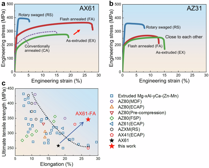
a Engineering stress-strain curves of as-extruded (green solid line), rotary swaged (blue solid line), conventionally annealed (purple dashed line), and flash annealed (red solid line) AX61. AX61-FA exhibited substantially higher strength and elongation than AX61-EX and AX61-CA. b Engineering stress-strain curves of as-extruded (green solid line), rotary swaged (blue solid line), and flash annealed (red solid line) AZ31. AZ31-FA was almost similar as AZ31-EX in strength and ductility. c UTS and tensile elongation of AX61-FA compared with other rare-earth-free Mg alloys under various processing conditions (References of these data points are listed in the Supplementary Fig. 5).
Following RS, flash annealing was applied to both alloys. The tensile stress-strain curves indicate that the strength and ductility of AZ31 degraded to nearly the same level as in its as-extruded condition (AZ31-EX), suggesting that most of the defects introduced during RS were likely eliminated during FA. In stark contrast, AX61 exhibited simultaneous improvement in strength and ductility after FA (AX61-FA). To assess the efficacy of the flash annealing, conventional annealing (CA) was additionally performed on the rotary-swaged AX61 alloy in a salt bath. As shown in Fig. 1 and Table 1, both the yield strength and tensile elongation of AX61-CA were much lower than those of AX61-FA. The combination of ultimate tensile strength (UTS) and elongation in AX61-FA surpasses that of almost all other rare-earth-free (RE-free) Mg wrought alloys, including those processed by methods such as MDF, ECAP, or friction stir processing (FSP) (Fig. 1c). This outstanding tensile performance of AX61-FA can be attributed to the unique microstructure developed during the FA process, as discussed in the following sections.
Generation of numerous < c + a> dislocations in AX61 after RS + FA processing
A significant level of lattice distortion was observed in AX61-RS by electron backscatter diffraction (EBSD), as shown in Fig. 2a. The mean kernel average misorientation (KAM), which quantifies the extent of lattice distortion, reached 2.36°. In contrast, AZ31 exhibited less severe lattice distortion after RS (AZ31-RS), with a mean KAM value of 1.89°. Notably, numerous deformation twins were present in AZ31-RS (Fig. 2b). These results suggest that the severe plastic strain induced by RS in AX61 was primarily accommodated by dislocations, while in AZ31, both deformation twins and dislocations played a role.
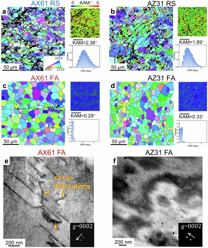
a EBSD inverse pole figure (IPF) map and KAM map of AX61-RS. In the IPF map, grains in red color have their <0001> axis being close to the extrusion direction, while grains in blue or green colors have their <0001> axis being nearly perpendicular to the extrusion direction. Large lattice distortion is observed, suggesting a high density of dislocations. b IPF map and KAM map of AZ31-RS. Deformation twins are prolific in the sample. c, d IPF map and KAM map of AX61-FA and AZ31-FA. e, f Two beam bright field TEM images of AX61-FA and AZ31-FA, taken along the [2(bar{11})0] axis under g = (0002) condition. AX61-FA contained many <c + a> dislocations, while AZ31-FA was free of <c + a> dislocations.
After FA, the mean KAM in both AX61 and AZ31 substantially decreased (Fig. 2c, d), indicating the lattice distortions caused by rotary swaging were largely recovered. Deformation twins in AZ31-FA also disappeared. Surprisingly, many <c + a> dislocations were identified in AX61-FA by TEM (Fig. 2e), while AZ31-FA was almost free of <c + a> dislocations (Fig. 2f).
Abundant < c + a> dislocation activity in AX61-FA during tensile loading
Based on the EBSD-measured grain orientations, slip trace analysis was performed on an AX61-FA sample after 4% tensile strain. Slip traces of pyramidal II <c + a> slip (i.e. ({11bar{2}2}, < 11bar{23} > )) were identified, with two examples shown in Fig. 3a, b. A statistical analysis covering 117 grains (Fig. 3c) indicates that basal <a> slip accounts for approximately 56% of the total activated slip modes, while non-basal slip modes, including prismatic <a > , pyramidal I <a > , and pyramidal II <c + a> slip, constitute about 44% (Fig. 3d). Notably, pyramidal II <c + a> slip represents 6.8% of all observed slip lines. Figure 3e, f display TEM images of <c + a> dislocations in AX61-FA, confirming their extensive activation. In contrast, slip trace analyses on AX61-EX (176 grains) and AZ31-EX (75 grains) show that basal slip is the predominant mode, comprising up to 85% and 89% of the total slip modes in these two samples (Fig. 3d). Pyramidal II <c + a> slip accounts for only 2.9% in AX61-EX and is almost nonexistent in AZ31-EX.
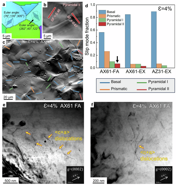
a, b An example of slip trace analysis showing pyramidal II slip lines in two grains, which were attributed to <c + a> slip. c Slip trace analysis of more grains from a larger area, where different line colors represent different slip planes (i.e. blue lines: basal planes; orange lines: prismatic planes; green lines: pyramidal I planes; red lines: pyramidal II planes). d Statistics of the identified slip activities in AX61-FA, AX61-EX, and AZ31-EX. e, f Two beam bright field TEM images of a AX61-FA sample after 4% tensile strain, taken along the [2(bar{11})0] axis under g = (0002) condition. Many <c + a> dislocations show zig-zag morphology, suggesting cross-slip.
Precipitates and atomistic clusters in AX61-FA
The YS of AX61-FA is significantly higher than that of AX61-EX and AX61-CA. According to EBSD analysis (Supplementary Fig. 1), AX61-EX, AX61-CA, and AX61-FA exhibit similar texture; average grain sizes of AX61-EX and AX61-CA are even smaller than that of AX61-FA. Therefore, the high strength in AX61-FA must be attributed to finer microstructural features.
Figure 4a shows the X-ray diffraction line profiles of AX61 at different conditions. Al2Ca peaks are identified in all four samples. According to TEM observations, AX61-FA contains many Al2Ca nanosized precipitates (Fig. 4b and Supplementary Fig. 2), while Al2Ca in AX61-EX and AX61-CA often exist as coarse particles. The nanosized Al2Ca precipitates can effectively inhibit dislocations (Fig. 4c) and so offer strengthening.
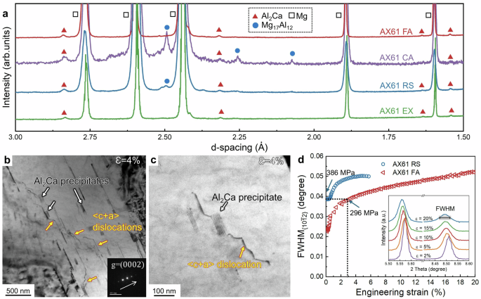
a Integrated diffraction line profiles for AX61 in the as-extruded (green solid line), rotary swaged (blue solid line), conventionally annealed (purple solid line), and flash annealed (red solid line) states. Al2Ca peaks are observed in all four samples. Mg17Al12 peaks were found in the rotary swaged sample, but disappeared after flash annealing. b, c Bright field TEM images of an AX61-FA sample after 4% tensile strain, showing the interaction between <c + a> dislocations and Al2Ca precipitates. d FWHM of the ({10bar{1}2}) peak at different tensile strains in AX61-RS (blue circles) and AX61-FA (red triangles).
In addition to forming Al2Ca precipitates, Al and Ca atoms can also form clusters in Mg lattice. According to recent studies34,35, Al-Ca atomistic clusters were found in Mg-Al-Ca-Mn alloys, and these clusters can enhance the CRSS by 16 ~ 46 MPa for different slip systems. To explore the existence of Al-Ca atomistic clusters in AX61-FA, we analyze the evolution of the diffraction profiles with strain in AX61-FA from the in situ synchrotron X-ray diffraction experiment, as shown in the inset of Fig. 4d. In general, all diffraction peaks of Mg broaden with increasing strain. Figure 4d shows the full width at half maximum (FWHM) for the ({10bar{1}2}) peak at different tensile strains. Before the tensile test, the ({{{{rm{FWHM}}}}}_{{10bar{1}2}}) of AX61-RS is much higher than that of AX61-FA due to the higher defects density in AX61-RS. ({{{{rm{FWHM}}}}}_{{10bar{1}2}}) of AX61-FA at 3% strain was almost same as that of AX61-RS at 0 strain, despite AX61-FA having a much lower flow stress at 3% strain (296 MPa) compared to the YS of AX61-RS (386 MPa). This suggests that the peak broadening in AX61-FA is influenced by factors beyond dislocations alone. It is known that clusters of solute atoms can make lattice distortion locally, leading to a nonuniform distribution of crystal plane distance. So the additional diffraction peak broadening in AX61-FA can be attributed to the existence of Al-Ca atomistic clusters.
Discussion
The rotary swaging + flash annealing process substantially enhances the strength and ductility of AX61, but it proves almost ineffective for AZ31. To understand the underlying mechanism, we first examine the differences in microstructure evolution between these two alloys under the same processing conditions.
Rotary swaging is a process involving high speed and multi-directional strains, which induces a high density of dislocations, especially <c + a> dislocations36. The major difference between AX61-RS and AZ31-RS is that the latter contains many deformation twins, while the former does not. To understand this difference, molecular dynamics (MD) simulations were conducted to calculate the critical stress for twin boundary migration in models with nominal compositions of Mg-3Al-1Zn and Mg-6Al-1Ca (both in wt.%), as illustrated in Fig. 5a, b. During the shear deformation, twin boundary migrates along the z direction, facilitated by the motion of twinning dislocations (Supplementary Fig. 3). As shown in Fig. 5c, the critical stress for twin boundary migration was higher in AX61 than in AZ31, suggesting that deformation twins are more difficult to grow in AX61. This finding aligns with the observation of fewer deformation twins in AX61 (Fig. 2a). During flash annealing, the deformation twins in AZ31 quickly disappeared (Fig. 2d), resulting in a microstructure and tensile stress-strain curve for AZ31-FA that closely resemble those of AZ31-EX (Fig. 1b).
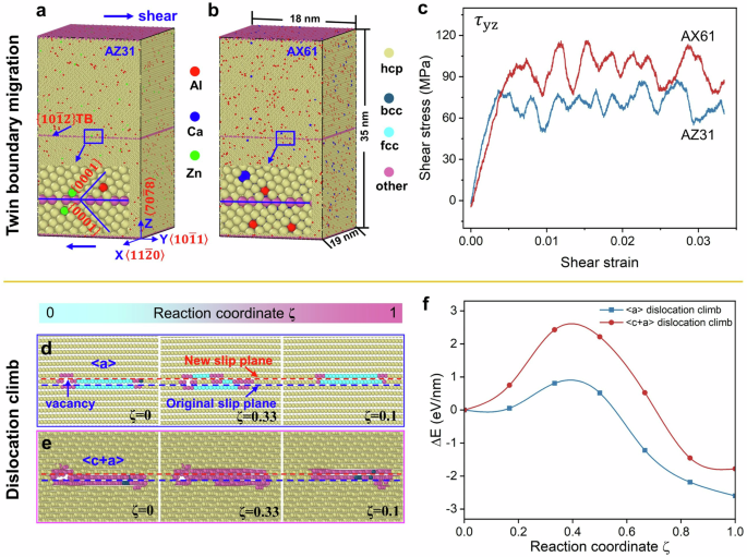
a, b The atomistic models with nominal compositions of Mg-3Al-1Zn and Mg-6Al-1Ca (both in wt.%) were constructed, where the solute atoms are randomly distributed. In each model, a (left{10bar{1}2right}) twin boundary was introduced so that the upper part and the lower part are symmetric to each other. c The shear stress-strain curves during twin boundary migration in AZ31 (blue solid line) and AX61 (red solid line). d, e The atomic climb processes of <a> and <c + a> dislocations in Mg lattice and (f) the corresponding energy evolution during <a> and <c + a> dislocation climb.
In the absence of sufficient deformation twins, the AX61 alloy must generate a higher density of <c + a> dislocations to accommodate strain along <c> axis. A significant portion of these <c + a> dislocations are retained after flash annealing, while most <a> dislocations are eliminated (Fig. 2e). To understand the retaining of <c + a> dislocations, MD simulations were used to calculate the energy barriers for the climb of <a> and <c + a> dislocations in Mg lattice (Fig. 5d, e), revealing a significantly higher barrier for the latter (Fig. 5f). This explains the increased presence of <c + a> dislocations after flash annealing. These <c + a> dislocations are then primed for glide during subsequent deformation, thereby enhancing ductility. Additionally, they contribute to forest hardening, further strengthening AX61-FA.
The formation of nanosized Al2Ca precipitates significantly contributes to the high strength in AX61-FA. Figure 6a shows the equilibrium phase fraction as a function of temperature for the AX61 alloy based on thermodynamics calculation. Up to 500 °C, Al2Ca is an equilibrium phase in AX61. Therefore, Al2Ca particles are expected to exist after homogenization (at 450 °C) and extrusion (at 250 °C), as well as after rotary swaging and flash annealing. Mg17Al12 was unstable above 300 °C, so it was effectively eliminated during homogenization. During rotary swaging, temperature in the rod was likely to increase, so a small amount of Mg17Al12 could form again, which explains the presence of Mg17Al12 peaks in AX61-RS. According to finite element method (FEM) simulation, the temperature rapidly rises to about 450 °C during induction heating (Fig. 6b), causing the above Mg17Al12 to re-dissolve into Mg matrix. The increased Al content in the Mg matrix could lead to the nucleation of Al2Ca nano-precipitates in AX61-FA. The temperature increase of the sample during conventional annealing is much slower (Fig. 6b), so Mg17Al12 could form in the AX61-CA sample. Al2Ca nano-precipitates have a much better strengthening capability than Mg17Al12, and the latter often causes fracture during deformation, which can explain why AX61-FA exhibits higher strength and ductility than AX61-CA. These Al2Ca nano-precipitates not only strengthen the material, but also act as obstacles to dislocation climb, aiding the retention of <c + a> dislocations during flash annealing.
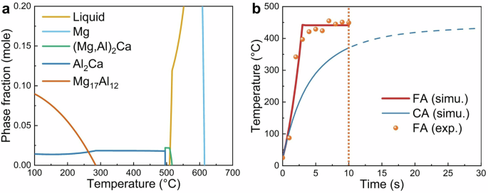
a Calculated phase fractions as a function of temperature in AX61. b Temperature evolution under flash annealing and conventionally annealing from infrared thermal imaging experiment and FEM simulation.
In addition to Al2Ca nano-precipitates, Al-Ca clusters were also likely to form during flash annealing. Thermodynamics calculations reveal that the mixing enthalpy of the Al-Ca pair is highly negative37. In a previous study34 of an Mg-1.3Al-0.3Ca-0.5Mn (wt.%) alloy extruded at 275 °C, homogenized at 500 °C for 10 min, followed by water quenching and a subsequent aging at 200 °C for 0.5 h, a high density of Al-Ca Guinier-Preston (G.P.) zones were identified by 3D atom probe tomography (APT). It is estimated these Al-Ca G.P. zones increase the CRSS of basal slip by 16 ± MPa and the CRSS of prismatic slip by 46 ± MPa. In our case, flash annealing was performed at 450 °C for 10 s in a microstructure full of dislocations. It is possible for some Al-Ca clusters to form, and these clusters offer a moderate strengthening.
The YS of AX61-FA is 95 MPa higher than that of AX61-EX. Table 2 summarizes the estimated contribution of individual strengthening mechanisms. The Orowan strengthening by nanosized Al2Ca precipitates, ({Delta sigma }_{{ppt}}), is estimated to be ~ 30 MPa (Supplementary Note 1). The retained <c + a> dislocations in AX61-FA provide a forest hardening (({Delta sigma }_{{forest}})). From TEM images (Supplementary Fig. 4), the density of <c + a> dislocations in AX61-FA is approximately 1.05 × 10¹³ m−2. Using the Taylor Equation (Supplementary Note 2), ({Delta sigma }_{{forest}}) is estimated to be 25 MPa. The grain sizes of AX61-FA and AX61-EX are 18 μm and 15 μm, respectively. Using the Hall-Patch coefficient of 200 MPa·(μm)1/2 in the literature38,39, the contribution of grain size strengthening (({Delta sigma }_{{gs}})) is −5 MPa. Finally, the contribution of Al-Ca cluster strengthening (({Delta sigma }_{{cluster}})) is estimated to be 45 MPa to account for the YS difference between AX61-EX and AX61-FA.
Figure 7 summarizes the microstructure evolution in AX61 during rotary swaging and flash annealing. During extrusion, micro-sized Al2Ca precipitates formed in AX61. After rotary swaging, both <a> and <c + a> dislocations are introduced. Following flash annealing, the retained <c + a> dislocations, along with Al2Ca nano-precipitates and Al-Ca clusters, contribute to the alloy’s exceptional tensile properties. Given that AX61 contains no rare earth elements and the rotary swaging + flash annealing process can be completed in a relatively short time, this work offers a promising Mg alloy for consideration in the aerospace industry. The alloy design strategy could also be applied to other metal systems.
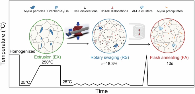
Rotary swaging induced a high density of dislocations. After flash annealing, <c + a> dislocations were retained; Al2Ca nanoprecipitates and Al-Ca clusters formed.
Methods
Materials fabrication and tensile test
To prepare the alloy with nominal composition of Mg-6Al-1Ca (wt.%), commercial pure Mg, pure Al, and a Mg-30Ca(wt.%) master alloy were melted and casted. The actual alloy composition was determined using Inductively Coupled Plasma Atomic Emission Spectroscopy (ICP-AES) analyzer (Perkin-Elmer, Plasma 400) as Mg-5.8Al-0.76Ca (wt.%). After homogenization at 450 °C for 24 h, the alloy was extruded at 250 °C into rods with a diameter of 20.6 mm. The extrusion ratio was 16:1. A four-die rotary swaging machine was employed to refine the microstructure of the extruded rods of AX61 and AZ31 alloys. During the swaging process, four dies symmetrically surrounded the rod’s circumference. These dies rotated at high speed performing high-frequency, short-range radial strokes. This intense mechanical working reduced the initial rod diameter from 20.6 mm to 18.8 mm, imposing an equivalent strain (ε) of 18.3% on the alloys. Samples from the radial center of the rod were extracted for this study.
Some of the rotary swaged rods were flash annealed using a high-frequency inductive heating instrument (SPG-20, Shenzhen Shuangping Power Technology Co. Ltd.) in a coil with a diameter of 80 mm. The frequency of the alternating electromagnetic field was 540 kHz. An infrared thermal imager (MAG42, Shanghai Magnity Technologies Co. Ltd.) was employed to record instantaneous temperature of the sample during inductive heating. After 10 s of inductive heating, the rods were water quenched. Conventional annealing in a salt bath was conducted for comparison. An Al2O3 crucible filled with NaCl powder was preheated at 450 °C for 30 min, then some rotary swaged AX61 samples were immersed into the NaCl powder for 10 s and subsequently water quenched.
Dog-bone-shaped tensile specimens with gauge dimensions of 15 mm (length) × 4 mm (width) × 1.5 mm (thickness) were extracted from the as-extruded, rotary swaged, and flash annealed rods. The tensile axis was aligned parallel to the extrusion direction. Tensile tests were performed using a ZwickRoell instrument (Z100 TEW) at a constant strain rate of 1 × 10⁻³ s−1.
FEM simulation of flash annealing and conventional annealing
Finite element method (FEM) simulation was performed using COMSOL Multiphysics. For flash annealing, a Mg rod was placed at the center of a 7-layer copper coil subject to an alternating electromagnetic field with the frequency of 540 kHz. For conventional annealing, a Mg rod was placed in a NaCl media at 450 °C for 10 s. The temperature evolution of the two Mg rods were computed based on Faraday’s Law of induction and Fourier’s Law of heat conduction, respectively.
Microstructure characterization and in-situ testing
Scanning electron microscopy (SEM) and electron back-scattered diffraction (EBSD) were performed using a MIRA3 instrument (Tescan, Czech Republic). The EBSD data were analyzed using TSL OIMTM software (EDAX Inc., USA). Further characterizations was performed using transmission electron microscopy (TEM) in a Talos F200X G2 instrument (FEI, USA).
In-situ synchrotron X-ray diffraction experiments were conducted at Beamline P21.2 of the Deutsches Elektronen-Synchrotron (DESY), Germany. The X-ray energy was 52 keV, equivalent to a wavelength of 0.2386 Å. The beam size was 150 × 150 μm2. Diffraction signals were recorded using a Varex XRD4343CT detector (2880 × 2880 pixels). The detector geometry parameters were calibrated using a CeO2 standard sample. Flat dog-bone shaped tensile specimens with gauge dimensions of 4 mm (length) × 1 mm (width) × 1 mm (thickness) were extracted from the rods, with the tensile axis being parallel to the extrusion direction. The in-situ tensile test was conducted at a nominal strain rate of 1.0 × 10⁻³ s−1, with diffraction patterns recorded intermittently.
Molecular dynamics (MD) simulations
The Large-scale Atomic/Molecular Massively Parallel Simulator (LAMMPS) package was utilized for MD simulations40. The modified embedded atom method (MEAM) interatomic potentials for Mg-Al-Zn and Mg-Al-Ca alloys were employed41. Periodic boundary conditions (PBC) were applied along the x and y axes. Prior to shear deformation, molecular static calculations using the conjugate gradient method were performed for energy minimization to achieve equilibrium configurations. Subsequently, the samples were relaxed for 10 ps under the Nosé–Hoover isobaric-isothermal (NPT) ensemble at 300 K. Shear deformations were executed using the NPT ensemble, with the top atoms subjected to prescribed shear displacement, while the bottom atoms remained fixed (thickness = 1 nm). The applied shear strain rate, (dot{gamma }), was set at 2 × 10⁸ s−1, with a timestep of 1 fs for all MD simulations.
The energy barriers for the climb of <a> and <c + a> dislocations were investigated using molecular static calculations. The <a> and <c + a> dislocations dipoles were constructed in Mg by applying the corresponding Volterra’s displacement field in the case of isotropic elastic medium to satisfy the PBC in all three axes42. For <a> dislocations, the simulation cell axes x, y, and z were aligned along, (leftlangle 1bar{1}00rightrangle), (leftlangle 11bar{2}0rightrangle) and (leftlangle 0001rightrangle) respectively. For <c + a> dislocations, the x, y, and z axes of the simulation cell were aligned along (leftlangle 58bar{13}3rightrangle), (leftlangle 11bar{2}3rightrangle) and (leftlangle 7bar{7}04rightrangle), respectively. The dimensions in y and z axes were 30 nm, while the x axis dimension corresponded to one unit of the direction vector for both models. A slice of atoms with the width of one Burger vector was removed from the slip plane to generate vacancies for both models to assist dislocation climb. The calculated energy barrier represents the energy per unit length along the x axis.
All atomic configurations were visualized using OVITO43, with atoms colored according to the common neighbor analysis (CNA) method44: yellow, green, and cyan represent hcp, bcc, and fcc atoms, respectively, and magenta denotes other structures.

Responses