Holomorphic embedding method for large-scale reverse osmosis desalination optimization
Introduction
Large-scale optimal design problem arises in various research areas, which covers craft manufacturing, chemical engineering, energy engineering and many fields. Here are a bunch of examples including optimal aircraft design1,2,3, chemical process optimization4,5, optimal design of stabilizers in power system6,7, optimization for energy storage and use8, etc. The development of real-time calculation in large-scale optimal design processes is valuable, as it may considerably promote iterative design and innovation, boost customized design, and augment adaptability to technological and market shifts9,10,11. Numerous large-scale optimal design problems, however, are still difficult to be tackled in practical applications with real-time requirements12,13,14. One of the primary obstacles lies in their mathematical challenges, which includes the nonlinearity and high-dimensionality of objective and constraint functions, the mixed nature of design variables, to name a few13. The effectiveness of design optimization is limited by the computational complexity related to the design evaluation, particularly in the simulation of nonlinear differential equations (NDEs)13,14. Consequently, it’s meaningful to develop efficient numerical methods and corresponding simulation solvers for NDE in specific design problem.
Freshwater scarcity is one of the most urgent global challenges. Reverse osmosis (RO), a prevalently employed desalination technology, facilitated by the external pressure, separates undesirable solutes from the solvent through a semi-permeable membrane to procure freshwater15. The influence of various membrane properties, membrane module design and arrangement, operating conditions, and other configurations of RO systems on the produced water quality, recovery rate, system energy consumption, etc. has been studied in-depth16,17,18,19,20. In recent years, advanced membrane materials have attracted widespread attention due to their advantages such as high water-permeability, strong mechanically strength, suiting wide pH and strong oxidants, etc20, which leads to performance improvement and cost optimization. However, there is an upper bound of membrane performance due to the limitations in fluid mechanics and mass transfer in realistic RO system19,20. Therefore, membrane module design of RO system must be improved to match the development of advanced membrane19,20. A hybrid model that couples a three-dimensional computational fluid dynamics model at submillimeter-scale and a one-dimensional system-level model at meter-scale is built for simulating the RO process16,17. The one-dimensional system-level model, mathematically formulated as a system of differential algebraic equations (DAEs) (2), is intrinsically linked to the operating condition, arrangement of membrane module and various design configuration of the RO system18. It requires to solve many DAEs with various design variables to find an optimal solution. To minimize the cost, selecting an efficient numerical method for solving DAEs is critical.
The classical method popularly utilized for solving DAEs includes Euler method, trapezoidal method, Runge-Kutta method, Adams methods, backward differentiation formula (BDF) method, among others21,22,23. Notably, the Runge-Kutta and BDF methods are frequently employed, the former is favored for solving non-stiff equations, while the latter is particularly effective for stiff equations23,24. Especially the BDF method, was first proposed by Curtiss and Hirschfelder in 195224. Owing to the contributions of Gear25, BDF method earns general acceptance for the integration of stiff differential equations, essentially due to its good stability-properties. Building upon the BDF framework, the numerical differential formulas (NDF) method is derived as a variant that renders augmented stability and greater efficiency26,27,28. In modern engineering practices, BDF or its variants are extensively applied29. These traditional methods employ a small-step iteration technique to directly ascertain solutions at discrete points from the solution at previous points, requiring that the step size be sufficiently small to satisfy accuracy for the given equations. While effective in many cases, the speed of this technique is constrained by the large number of small-step iteration needed when dealing with large-scale problems. In 2018, a fast and flexible holomorphic embedding (FFHE) method was firstly proposed by Wang et al.30 to calculate the power flow in large scale power systems with quick speed and high accuracy successfully. Compared to those traditional small-step iteration methods, FFHE method is a promising numerical tool for large-scale problems. It breaks away from the small-step iteration paradigm and uses the idea of function approximation in a piece-wise manner to construct solutions, which provides FFHE with fast, accurate, and memory-efficient advantages30,31,32,33. Besides, the framework of FFHE could be directly used to solve a variety of common mathematical equations, thereby offering a broad range of applications34,35,36.
Inspired by those works, we design a semi-analytic algorithm based on FFHE that enables to solve the hybrid model in RO desalination efficiently, as a first step toward addressing the multi-scale optimal design problem in the next work. Furthermore, the accuracy of FFHE is validated using a representative case study from industry. Subsequently, we benchmark the efficiency of the proposed algorithm against commonly used solvers in MATLAB within the context of the multi-scale optimal design problem of RO system. Finally, the algorithm is applied to evaluate the effect of advanced membrane materials in high permeability seawater RO desalination systems.
Results
Overview of the FFHE method
The FFHE method is a computational framework that could be utilized to efficiently solve common mathematical equations numerically. It typically sequentially comprises four stages: initially deriving power series representation of the solution, subsequently deriving rational approximant for the solution, then adaptively segmenting interval, and concluding with composing high accuracy approximate solution quickly30 (Fig. 1). It possesses the features such as stepping outside of the small-step iteration framework of conventional numerical techniques, independently building rational approximants for every subdivided interval, and flexibly subdividing the interval as per the preset precision demand. Owing to the less computational domain segments and great precision of rational approximation37,38, FFHE method exhibits desirable computing speed with guaranteed accuracy. In this work, a four-stage algorithm based on FFHE is designed to numerically solve the one-dimensional system-level model (2) for RO system (see the section “Methods”).

First, finding an initial point of the computational interval. Step1: to get the power series representation of the solution function. Step 2: to get the rational approximant of the solution function. Step 3: to do an adaptive segmentation in the computational domain by the predicting error test. If the test is passed, then advance to the next point of the interval, else return to the Step 1. With that action, the error of the numerical solution is expected to be bounded within preset error tolerance. Step 4: to integrate piecewise solutions generated by adaptive segmentation into a global approximate solution. The red star denotes the segmentation points chosen by the adaptive segmentation.
Method validation
Numerical experiments are conducted on cases from waterworks in Chino Desalter I located in Chino, California39, validating the effectiveness of our algorithm. A two-stage RO desalination process16 (Fig. 2) is simulated and the results (transmembrane pressure ΔP, flow rate Q) of simulation and measurement are shown in Fig. 3. The solution solved by FFHE (blue curves) and NDF (solid black dots) almost overlap everywhere with relative error of the order of 10−3. Compared with the actual measurements data (red hollow circles in Fig. 3) collected from industry, simulated results of Q are consistent while the outcomes derived for ΔP display discrepancies with absolute error of 0.19 bar at X = 1 and 0.38 bar at X = 2. This is primarily resulting from the decline in membrane performance over extended periods of use in industrial settings39. The remarkable precision of the algorithm is attributed to the high order truncation error and adaptive segmentation according to preset accuracy. Theoretically, the rational approximants used in this case reach the truncation error of order O (10), which can be traced back to the truncation number used of power series. Moreover, each adaptive segmentation in Fig. 3 (marked as a red star) ensures the error of the numerical solution within a predefined level, which is achieved by setting absolute error bound ε in criteria (10) as (3times {10}^{-5}). More details about algorithm are provided in section “Methods”.
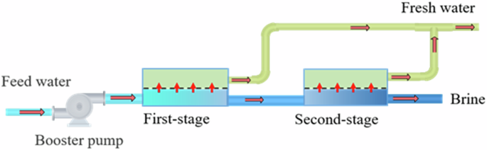
A two-stage brackish water reverse osmosis system.

The numerical solutions calculated by fast and flexible holomorphic embedding (FFHE) method, numerical differential formulas (NDF) and the factory measurement data points of a transmembrane pressure (Delta P), b flow rate (Q). c Relative error of estimated (Delta P) using FFHE compared with that of the NDF. d Relative error of estimated (Q) using FFHE compared with that of the NDF. An adaptive segmentation technology is employed in FFHE and the red star denoted in the plot represents the segmentation point. (X) represents the normalized length from inlet to outlet for the RO system (First stage: (Xin [0,1]); Second stage: (Xin [1,2])).
Computational efficiency evaluation
Furthermore, numerous equations from the optimal design problem of RO system (as is introduced in the section of “Problem description”) are solved using the FFHE and commonly-used computational solvers in MATLAB27,28,40,41,42 with respect to 100, 1000, 10000 and 100000 design parameters (or geometrical parameters of feed spacer) respectively (see Table 1). These solvers encompass implementations of classical numerical calculation methods such as the trapezoidal rule, Runge–Kutta method, BDF method, NDF method and others. For each group, the solver based on FFHE consumes the least time on average compared to all MATLAB solvers. As the equations get more and more, the results indicate that FFHE can even achieve about 6x speed-ups than the most efficient solver in MATLAB (ode15s). The superior efficiency arises from the piecewise function approximation idea of FFHE, which jumps out of the small-step iteration framework of traditional methods and hence to avoid large amounts of iterations during the calculation process. In light of this, the main cost is incurred in the calculation of coefficients for deriving the approximation function piece-wisely. Thus, a smaller number of interval segments in Stage 3: Adaptive Segmentation (see the section “The FFHE method”) also expedites the calculation and further improves the efficiency.
Application in evaluating the effect of advanced membrane
The hydraulic permeability ({L}_{{rm{p}}}) measures the ability of membrane to be permeable by the fluid, which describes the capability of purification and desalination of water. The proposed algorithm based on FFHE is applied to evaluate the effect of seawater RO systems with different high permeable membranes (Figs. 4 and 5). The estimated results (transmembrane pressure, flow rate and permeation flux) obtained from the FFHE and ode15s solver in MATLAB are completely consistent with respect to various (X) and ({L}_{{rm{p}}}) (Fig. 5). Specific energy consumption (SEC) and maximum concentration polarization factor (Max CPF) under a fixed recovery rate of 50% are illustrated in Fig. 6. It shows that the SEC declines sharply from 2.59 kWh m−3 to 2.21 kWh m−3 (decreased by 17.2%) as ({L}_{{rm{p}}}) increases from 1 Liter m−2 hour−1 bar−1 (lmh bar−1) to 3 lmh bar−1 then levels off when ({L}_{{rm{p}}}ge 3) lmh bar−1. Hence, developing advanced membrane materials with high permeability does not always lead to reduced energetic costs, but can help reducing the required membrane area. To avoid an acceleration of membrane fouling and a decline of driving force, practically, Max CPF is controlled to no more than 1.2 in generic flow arrangements for membrane modules18,20. Figure 6 displays that Max CPF grows almost linearly with Lp and is near 1.2 when Lp reaches 3 lmh bar−1, which also hinders the application of most high permeable membranes in existing factory settings. The concentration polarization can be reduced by membrane module optimization and system design43. Calculation formulas about SEC and Max CPF can be found in article18.

a Transmembrane pressure (Delta P). b Flow rate (Q). c Permeation flux ({J}_{{{{rm{W}}}}}). (X) represents the normalized length from inlet to outlet for the reverse osmosis system.

a Transmembrane pressure ((Delta P)) calculated by FFHE. b (Delta P) calculated by ode15s. c Flow rate ((Q)) calculated by FFHE. d (Q) calculated by ode15s. e Permeation flux (({J}_{{{{rm{W}}}}})) calculated by FFHE. f ({J}_{{{{rm{W}}}}}) calculated by ode15s. (X) represents the normalized length from inlet to outlet for the reverse osmosis system.

a Specific energy consumption (SEC). b Maximum concentration polarization factor (Max CPF). The black dotted line denotes an upper bound of the Max CPF in generic flow arrangements for membrane modules.
Discussion
The proposed numerical method based on FFHE in this work enjoys a few notable advantages:
High speed
FFHE constructs approximate solution by the power series representation and rational approximant of the solution. Unlike traditional methods with small-step-iteration paradigm, it does not need to calculate an approximate value at each discrete point iteratively, but instead constructing an accurate approximation function in each interval independently. Since the Padé approximant expands the convergence effectively31,37, the algorithm can quickly advance to the end.
High precision
According to predetermined accuracy, adaptive segmentation is executed in the solution process to ensure precision. In each interval segment, approximate function with high-order truncation error ensures the local convergence of the solution.
High space-utilization
To store the approximate solution, FFHE simply requires saving the coefficients of power series or rational approximants of the solution. In order to attain the final results, however, the classical numerical method entails the store of the information for many intermediate points, which consumes substantial memory space.
High transferability
FFHE offers a numerical computation framework that is expected to be adaptable to solving equations corresponding to industrial application under practical conditions. FFHE is a promotable tool that could be used for engineering applications especially for large-scale problems (typically involve substantial numbers of equations or variables), which exert its efficiency advantage better.
Future optimization for this method could focus on better approximation function and strategies of adaptive segmentation, to further reduce the number of segments and enhance computing efficiency. From truncated power series to Padé approximant, the convergence domain is enlarged. Besides, a strategy that determining the optimal segment points in the computational domain is also worth researching. Both of them improve the performance effectively.
Methods
Problem description
A hybrid model is established to model the RO process16. The hybrid model couples a three-dimensional multi-physics (fluid flow and mass transfer) model with high fidelity at submillimeter-scale and a one-dimensional system-level model (differential algebraic equations, DAEs) at meter-scale. The detailed mathematical description for multiscale design optimization problem with constraints can be found in our previous work44. Like many multi-scale optimal design problems45,46, its object is to find an optimal design strategy for different scale to minimize the cost of the whole system within specific constraints. For RO systems, it involves the module design (or feed spacer design) at sub-millimeter scale and system design (configuration of operating conditions, module arrangement) at meter scale18,44. The process of finding optimal solutions requires solving a large number of non-linear differential equations, which is indispensable but time-consuming.
Three-dimensional computational fluid dynamics model is established by the Naiver-Stokes equation and continuity equation for the fluid flow and mass transfer processes in the RO desalination process, which could be described mathematically as44:
where computational domain (Omega) is determined by given geometric structure, ({{{bf{u}}}}equiv (u,v,w)), ({P}) are velocity vector along three-dimensional coordinate axes and hydraulic pressure, respectively. (rho ,(c)) and (mu ,(c)) denote density and viscosity of fluid associated with molar concentration of salt (c), respectively. ({D}_{s}) denotes the salt diffusivity.
One-dimensional system-level model at meter scale depicts the relationship among flow rate (Q), transmembrane pressure (Delta P), and water permeation flux ({J}_{{{{rm{W}}}}}) of the RO system in the feed direction, which is written as Eq. (2). (X) represents the normalized length from inlet (X = 0) to outlet (X = 1) for the RO system.
Instead of commonly used power function model16, quadratic polynomials are used to fit the function of the pressure drop per length and total average flow rate, the function of average mass transfer coefficient on the membrane surface and total average flow rate, which are ({F}_{{{{rm{new}}}}}(Q)) and ({K}_{{{{rm{new}}}}}(Q)) respectively in (2). Quadratic polynomial is accurate enough to fit and conducive to simplifying the derivation of the FFHE method. To determine the constant parameters({f}_{1},{f}_{2},{f}_{3},{k}_{1},{k}_{2},{k}_{3}) in ({F}_{{{{rm{new}}}}}(Q)) and ({K}_{{{{rm{new}}}}}(Q)), the least squares fitting method is applied. In addition, a theoretical proof about the existence and uniqueness of the solution of Eq. (2) is given in the section of “Existence and Uniqueness of Solution” of the Supplementary information.
The FFHE method
The algorithm based on FFHE that we proposed for solving DAEs (2) are mainly four stages. The first two stages demonstrate the techniques for constructing approximation function, and the last two stages present the process of adaptive segmentation and composing global solution.
Stage 1: Power Series Representation. Supposing that the solutions of Eq. (2) are all holomorphic on the function domain so that they could be represented by power series47. To determine the power series, algebraic equations about coefficients of each series term are constructed by inserting unknown power series into Eq. (2) and equating the coefficients for the terms of a same order on both sides after simplification. The analytic solutions of these algebraic equations lead to the algorithm of obtaining the power series. After that, a polynomial approximation of degree (q) is acquired through truncating the previous (q+1) terms of the series. Relating to the order of truncated error, generally, a considered value is chosen for (q) to balance the precision and efficiency. Next, a brief derivation is given and an algorithm to calculate coefficients of power series is formed in the end. More details are seen in the section of “Formula Derivation of FFHE” of the Supplementary information.
Assuming that the functions appeared in (2) could be expanded into power series at point ({X}_{0}) as in (3).
By substituting expression (3) into Eq. (2), differential equations are discretized and the coefficients of the power series could be calculated recursively.
The initial value conditions in the Eq. (2) tell us that when (X=0),
And ({c}_{0}) satisfies the non-linear algebraic Eq. (5),
To solve the value of ({c}_{0}), numerical method for solving nonlinear algebraic equations such as Newton Method is employed. Similarly as (4), (5), other constant terms are calculated by (6).
By (2) again, when (nge 1), the following relationship is hold.
Algorithm
Calculating coefficients of power series
Input: parameters in Eq. (2), (A,{Q}_{0},Delta {P}_{0},Delta {{{{rm{pi }}}}}_{0},{f}_{1},{f}_{2},{f}_{3},{k}_{1},{k}_{2},{k}_{3}). the degree of polynomial (q).
-
1.
Compute the coefficients when (n=0) by using Eqs. (4)–(6).
-
2.
Loop from (n:=1 ,{{mbox{to}}} ,q), calculate the coefficients by Eq. (7).
Output: the coefficients of the previous (q+1) terms truncated power series.
Stage 2: Rational Approximants. In order to improving the accuracy and efficiency, rational function (usually considering Padé approximant37,38) is constructed by previous q+1 terms of power series. Convergence domain of the solution is expanded compared to the polynomial approximation, which allows a wider range to approximate true solution. On each independent interval segment, the truncation error order can reach (O(m+n+1)) 30, where q = m + n, m and n are the degrees of the numerator and denominator of the rational function respectively. A brief introduction and the procedure to get the Padé approximant of the solution is found in the section of “Formula Derivation of FFHE” of the Supplementary information.
Stage 3: Adaptive Segmentation. When a point is far away from the expansion point, meaning outside the convergence domain of the function, the result obtained from power series or Padé approximant will be inaccurate37,38,47,48,49,50,51. To acquire numerical solution for the unsolved domain, another point will be chosen as a new expansion point to repeat the process of stage 1 and stage 2. From the previous to the next expansion point, it is like a person taking a step or leap. In the process of FFHE, the larger the length of each step, the fewer the number of expansion points and the better efficiency will be received. Because of the wide convergence region of the Padé approximation38, it is possible to select an aggressive step length to reduce calculation. In order to determine whether the point that has taken one step is qualified for being a new expansion point, we define a measure formula (9) and make an error predicting, which is the key criteria for adaptive segmentation. This stage actually divides the interval into different segments adaptively and constructs the approximate solution for each segment. To conveniently illustrate the rule of error predicting, DAE (2) is rewritten as an equivalent general form (8). (Q,Delta P,{J}_{{{{rm{W}}}}},X) are replaced with ({x}_{1},{x}_{2},{x}_{3},t), respectively.
A positive integer (q), an error bound (epsilon) (close to zero) are preset. Partitioning the interval ([a,b]) as (a={t}_{0}, < ,{t}_{1}, < ,cdot cdot cdot, < ,{t}_{n-1}, < ,{t}_{n}=b), a measure of error-predicting is defined as:
If the approximate solution ({{{bf{F}}}}(t)={({x}_{1}(t),{x}_{2}(t),{x}_{3}(t))}^{{{{rm{T}}}}}.) is close to the true solution of (8), then for any vector norm52 it must have
(PE(t)) characterizes the error between the approximate solution and the true solution. When (10) is satisfied, the point will be recognized as a new expansion point by our algorithm. To calculate derivative terms ({{{bf{F}}}}'(t)) in (9), finite difference formula could be utilized, such as central difference formula, forward difference formula, etc.53.
Stage 4: Constructing a global approximate solution. In this stage, the piecewise approximate solutions obtained at stage 3 will be integrated into a global solution over the whole interval. Assuming that the true solution of the equation is ({{{{rm{F}}}}}^{* }left(tright)={({x}_{1}^{* }left(tright),{x}_{2}^{* }left(tright),{x}_{3}^{* }left(tright))}^{{{{rm{T}}}}}) exactly. Suppose there are n segments in the global approximate solution. the solution ({{{{rm{F}}}}}left(tright)={({x}_{1}left(tright),{x}_{2}left(tright),{x}_{3}left(tright))}^{{{rm{T}}}}) that we construct will satisfy the following properties:
(1). In each segment ([{t}_{k},{t}_{k+1}],,k=0,1,cdots ,n-1), the approximate solution is the Padé approximate function mentioned in Stage 2: Rational Approximants.
(2). In each segment ([{t}_{k},{t}_{k+1}],,k=0,1,cdots ,n-1), the approximate solution ({{{bf{F}}}}(t)) could pass the predicting error test, which is:
It means that global approximation solution ({{{bf{F}}}}(t)) would converge to the true solution ({{{{bf{F}}}}}^{ast }(t)) within an error of no more than (epsilon) over the solution domain.
Responses