Low-error encoder for time-bin and decoy states for quantum key distribution
Introduction
The security of transmitted data is a critical point in our modern and interconnected society. Encrypted data are constantly under attack and the breakthrough of quantum computing poses a radical threat to the security of the modern classical cryptographic protocols1. In this scenario, unconditional security can be guaranteed only by taking advantage of the same quantum mechanics framework, so that Quantum Key Distribution (QKD) protocols stand out. QKD enables to share a secret key between two parties by exchanging quantum states2, typically encoded in light’s degrees of freedom (DoFs). A common encoding exploits the polarization DoF, which has been used to demonstrate QKD in both free-space3,4 and fiber-based links5,6,7,8. While for free-space links, there is no need to compensate for polarization’s changes in the channel, because of the negligible birefringence of atmosphere, for fiber optical channels the polarization drifts, induced by random environmental stresses, demand for an active compensation of the state transformation.
By being insensitive to birefringence, time-bin encoding has been extensively used as encoding in fiber optical QKD links as it overcomes the issue and removes the necessity of supervisioning perturbations in the channel. Reliability and robustness of time-bin encoding has been demonstrated by a number of experimental trials, in both laboratory environment9,10,11 and deployed fiber links12,13, with a plenty of different approaches mostly relying on fiber optics11,14 or integrated photonics15,16.
However, due to the need to stabilize and retrieve the relative phase between the time-bins, time-bin encoding usually requires the stabilization of local interferometers. Implementations are typically characterized by a higher intrinsic QBER compared to polarization implementation7.
One of the most widely used QKD protocols, implemented with both polarization and time-bin, is BB8417. This protocol has undergone successive refinements over the years to enhance key rates and to adapt the protocol assumptions to accommodate technological limitations. As a matter of fact, the original BB84 protocol requires the use of four prepared states, but three states have been shown to be sufficient to ensure security without penalty on the key rate18,19, allowing a further simplification of the transmitter design.
In addition, also the original requirement of using single photons has been relaxed.
Photonic states can indeed be encoded in phase-randomized attenuated laser pulses, which, however, expose the BB84 protocol to Photon Number Splitting (PNS) attacks20. A common countermeasure is the decoy state method21, which requires controlling the mean photon number of the transmitted pulse. For practical transmitters, this leads to the implementation of an intensity control stage, which is, in general, independent of the state encoder22.
The present work proposes an efficient and simple encoder design for the preparation of both time-bin states of arbitrary dimensions and arbitrary decoy levels in a compact and single optical topology. The device is all-fiber-based and exploits a Mach-Zehnder interferometer nested in a Sagnac loop, hence the name MacZac, to provide high extinction ratios and long-term stability. The MacZac can use as low as one phase modulator for both state encoding and decoy generation, greatly simplifying the experimental optical setup. We built an all-fiber prototype using only Commercial-Off-The-Shelves (COTS) components to characterize and verify the validity of the scheme for two-dimensional states (qubits). Thanks to its peculiar geometry, the device was capable of performing state encoding with an extremely high extinction ratio, showing a record-low intrinsic QBER of 2 × 10⁻⁵. The MacZac was then integrated into a complete QKD experiment to showcase its performance and advantages. By running the efficient three-state BB8423, with one-decoy method24, we achieved a steady distillation of a secret key, following from the extremely low QBER (<0.03% in key basis) provided by the encoder.
Such a device, combining high-performance, long-term stability with a practical and simple implementation, greatly simplifies the implementation of performant QKD transmitters, paving the way for more practical and low cost QKD systems.
Results
Proposed scheme
A common approach employed to generate time-bin states in QKD exploits an asymmetric interferometer, usually a Mach-Zehnder or Michelson type, which converts a pulsed laser source into a train of N successive pulses with known temporal delay and defined phases ϕj11,25,26. The parameters ϕj are controlled by means of phase modulators, electro-optical devices that change their refractive index when driven by an external electrical signal.
The appropriate mean photon number of each pulse, as required by the decoy protocol, is then prepared by an intensity modulator, as sketched in Fig. 1.
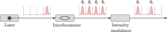
Laser pulses are distributed over N time bins (four in figure) and their phase is determined by an unbalanced interferometer structure. The desired amplitudes are selected by an intensity modulator.
Multiple technologies are available to perform intensity modulation of laser light. Examples are electro-optic or electro-absorption devices, whose working principle relies on the controllable change in a material property to directly apply the intended modulation27. The most common approach is to employ symmetric Mach-Zehnder inteferometers, which are available as COTS components and can support modulation bandwidths of several tens of GHz. However, these devices are sensitive to thermal and mechanical fluctuations, and they require an addition stabilization mechanism to operate in a stable way.
A simpler and more stable solution exploits unbalanced Sagnac interferometers, which do not require an active control since thermal and mechanical induced fluctuations are compensated by the double-pass topology28. Such a scheme does not only provides a better long-term stability, but, at the same time, it greatly simplifies the experimental implementation.
Based on the above observation, we here propose a scheme for the generation of time-bin states based on a unbalanced Mach-Zehnder interferometer included into a Sagnac based intensity modulator. The configuration allows to create time-bin states with extremely high-extinction ratio and decoy states with arbitrary intensity values, with a simple and stable setup. Since the loop layout avoids the use of an active compensation for relative phase drifts as mentioned before, the presented encoder ensures a practical and cheap implementation, where intensity and information encoding can be achieved by a single modulation stage, and besides, the design can be scaled to provide time states of arbitrary dimension. While the scheme can be employed for the generation of qudit states (i.e., d dimensional time-bin encoding) the following study starts by describing its working principles for qubits (2-dimensional states).
In Fig. 2 we show the design for qubits. Each 50/50 beam splitter (BSj) is characterized by transmissivity and reflectivity coefficients Tj = Rj = 1/2. The input BS1 equally divides the injected pulse into two modes that travel the Sagnac loop in clockwise (CW) and counterclockwise (CCW) directions, respectively. If E0 is the complex amplitude at the input, the amplitude of the mode propagating in the CW (CCW) direction is expressed by Eq. (1):
The CW mode (ECW) first propagates in the phase modulator, that applies a phase shift ϕc, and then it is transformed by the Mach-Zehnder interferometer, enclosed by BS2 and BS3, into a pair of pulses—early (e) and late (ℓ)—with identical amplitudes and with relative delay τ. The other one (ECCW) instead is first transformed into a pair of pulses, whose phases (ϕe and ϕℓ) can be selected by the phase modulators in the Mach-Zehnder interferometer arms. Here, for the sake of simplicity, we are assuming that the phase modulator(s) that acts on the CW (CCW) mode, is turned off before the CCW (CW) mode light propagates through it, so that it doesn’t apply any phase shift to the CCW (CW) propagating light. In other words, ϕc is applied only to the CW mode, while ϕe,ℓ is applied only to the pair of CCW modes.
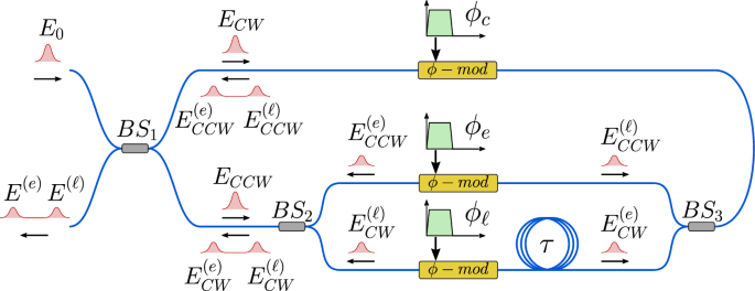
In this general scheme, each phase modulator is individually driven to modulate optical pulses traveling in a single direction: the phase modulator in the Sagnac arm modulates the CW pulse, while the phase modulators in the Mach-Zehnder modulate the CCW pulses. BS Beamsplitter, ϕ-mod phase modulator.
Before being recombined by the input BS1, the light pulses traveling in the loop have the complex amplitudes given by ({E}_{CW}={E}_{CW}^{(e)}+{E}_{CW}^{(ell )}) (and similarly for ECCW), where
and we assumed for simplicity eiωτ = 1, i.e., the relative phase imposed by the two arms of the unbalanced interferometer is zero. After the interference at the input BS1, it follows that the complex amplitudes at the output of the device of the e and ℓ pulses have the form of Eq. (3a).
The output (unnormalized) state can be written as
where (leftvert Erightrangle) and (leftvert Lrightrangle) are the e and ℓ time-bins while
From the above relation it is possible to see that the output quantum state can be controlled by properly setting the three phases ϕc, ϕe and ϕℓ. The transmittance Te,ℓ depends only on the phase difference between of ECW and ECCW modes, so that any phase drift experienced by the corresponding time-bin states is self-compensated by the closed-loop design (see Methods “Model of imperfections”). All BSs in Fig. 2 are assumed to be ideal, with a splitting ratio exactly of (frac{1}{2}). The analysis of the effect of imperfect BS is detailed in Methods “Model of imperfections”, the impact of those differences is shown to be small.
In the analysis above, the phase modulators are assumed to apply a phase shift only to a single pulse of light propagating in a single direction. However, by considering a more general regime in which traveling wave effects29 are not relevant, those devices act as phase modulators on light propagating in both directions. Therefore, the scheme can be simplified by using one phase modulator (see Fig. 3) as long as the different optical pulses ECW, ({E}_{CCW}^{(e)}) and ({E}_{CCW}^{(ell )}) travel the single modulator at distinct time instants. Indeed, in the latter condition, it is possible to apply arbitrary phases to the signals in the loop before they recombine. By suitably changing the modulating voltage signal at different times, the phase modulator can set the phases ϕc, ϕe, and ϕℓ. In this scenario, to generate (leftvert Erightrangle) ((leftvert Lrightrangle)), the control electronics applies an electric pulse to the phase modulator when is traveled by the e (ℓ) component of the CCW light. The (leftvert -rightrangle) state is produced by modulating the single CW laser pulse. This constitutes the main advantage provided by the interferometer nested structure, with respect to setups11,25,26 in which the state encoding is detached from the intensity modulation. Since the applied phase affects equally both the time-bin amplitudes, the ratio Te/Tℓ is independent of ϕc. To ensure the same mean photon number for the three states, the pulse applied to generate (leftvert -rightrangle) has to be smaller than the one used for (leftvert Erightrangle) and (leftvert Lrightrangle). Those amplitudes can be evaluated from the device response derived in Section “Transmitter characterization”. Having a single phase modulator makes the overall device cheaper and simpler, but demands an higher modulation speed. The device must be able to switch between the required phase values in a time comparable with the distance between the pulses of the time-bin state. On the other hand, the bandwidth constraint from the modulators in Fig. 2 is weaker, since the limiting factor arises from the repetition rate and the propagation delay between CW and CCW modes.
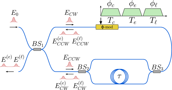
In this scheme a single phase modulator is used and electrical pulses are sent at different times to modulate either the CW, the CCW(e) or the CCW(l) pulses. BS Beamsplitter, ϕ-mod phase modulator.
The asymmetric Sagnac structure, which inherently implements an intensity modulator, allows to encode time-bin states and, at the same time, their decoy levels.
Since the transmittance depends on the applied phase shift, the mean photon number is set by controlling the amplitude of the signals driving the phase modulators. From the experimental point of view, this can be implemented with a Digital to Analog Converter (DAC) that is fast enough to generate the electrical signals driving the electro-optic phase modulators, as described in Methods “Qudit generalization”.
Transmitter characterization
In this work we were interested in developing and evaluating the performance of the MacZac in its simplest form, with only one modulator, since this provides the highest benefits in terms of optical implementation and cost-reduction. In the following we describe its experimental implementation and characterization.
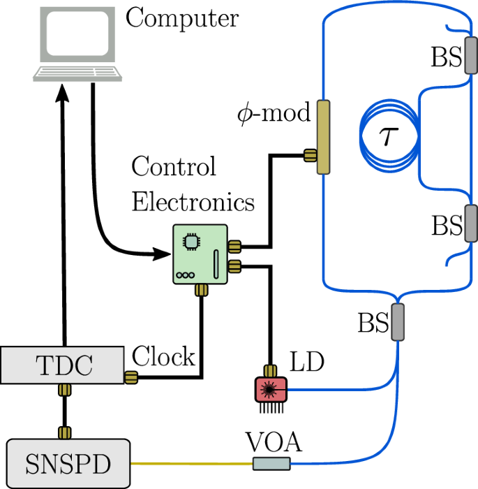
To measure the achievable performances of the encoder we built an experimental setup with COTS fiber components, as represented in Fig. 4. Specifically, the setup implements the single phase modulator layout (Fig. 3), and it includes an unbalanced Mach-Zehnder inteferometer with a delay of about 10ns, corresponding to 2 meters of optical fiber. Shorter delays, and thus higher repetition rates are possible if the fiber components are shortened and spliced together.
LD laser diode, BS beamsplitter, ϕ-mod phase modulator, TDL tunable delay line, VOA variable optical attenuator, TDC time to digital converter, SNSPD superconducting nanowire single photon detector.
All fiber components are polarization maintaining, BSs are fast axis blocking, i.e., they act as polarizing elements suppressing the mode traveling along the fast axis, and the phase modulator is a Lithium Niobate fiber modulator with 10 GHz electro-optical bandwidth. The light source is composed by a 1550 nm distributed feedback laser diode, driven in gain-switch mode, which generates laser pulses of about 50 ps width FWHM at 10 MHz repetition rate. Such a repetition rate was set in order to avoid the simultaneous modulation of more than one laser pulse inside the MacZac and, thus, to prevent eventual cross-talking effects, meanwhile simplifying the electronic control. Higher rates are feasible both by shortening the interferometer length and by improving the control logic. The ultimate limitation is then imposed by the propagation time in the phase modulator and by bandwidth constraints of the phase modulators and the driving electronics.
The control electronics (for details see Methods “Qudit generalization”) is designed to generate three states: (leftvert Erightrangle), (leftvert Lrightrangle) and the superposition (leftvert -rightrangle =frac{1}{sqrt{2}}left(leftvert Erightrangle -leftvert Lrightrangle right)), each with two possible amplitude levels μ and ν, with ν < μ. This enables to implement the three-states one-decoy efficient BB84 protocol30.
The states (leftvert Erightrangle) ((leftvert Lrightrangle)) with amplitude μ are obtained by setting phases ϕℓ = ϕc = 0 (ϕe = ϕc = 0) and ϕe = αμ (ϕℓ = αμ) with arbitrary 0 ≤ αμ ≤ π. On the other hand, to obtain the amplitude ν, the applied phase is αν such that
We note that the above equation define the values of αν in function of any arbitrary values of αμ as long as ν < μ.
The state (leftvert -rightrangle) is generated by setting ϕe = ϕℓ = 0. The value of ϕc is set to βμ for the high-intensity signal level μ and it is set to βν for the lower amplitude signal. The relation between βμ and βν is the same as the relation between αμ and αν while, to guarantee the same mean photon number in the produced (leftvert Erightrangle) or (leftvert Lrightrangle) and (leftvert -rightrangle) states, the following relations between αμ,ν and βμ,ν must hold
The applied phases for each generated state is summarized in Table 1. The control electronics drives the phase modulator in three different time slots TE, TL, and T−. The first two are the instants in which the CCW pulses cross the phase modulator and, whenever ϕe and ϕℓ are applied, they correspond to the generation of (leftvert Erightrangle) and (leftvert Lrightrangle) respectively. The latter allows to produce (leftvert -rightrangle) by setting ϕc to the single CW pulse.
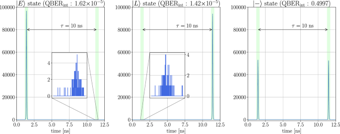
To evaluate the quality of the source, we tested it by preparing a stream of identical states which, after being attenuated down to less than one photon per pulse with a variable optical attenuator, were measured by means of a SNSPD (superconducting nanowire single photon detector). Detection events were collected by a time tagger, whose clock was synchronized with the one of the control electronics. Fig. 5 shows the histogram of the time of arrival over a period. These data are used to measure the intrinsic Quantum Bit Error Rate QBERint of the source, i.e.,
where Ncorrect are the number of photons detected in the correct time slot, and Nwrong the events happened in the wrong one. Another useful and closely related metric is the Extinction Ratio (ER) that, expressed in dB, can be evaluated from QBERint by taking (10{log }_{10}frac{{N}_{correct}}{{N}_{wrong}}=10{log }_{10}(frac{1}{{{rm{QBER}}}_{{rm{int}}}}-1)).
The diagrams represent the histogram of the time of arrival of the photons produced by the source and the corresponding extinction ratio.
By acquiring data for 1 min, with a detection rate of about 140k detections per second, we measured QBERint = 1.62 × 10⁻⁵ ± 1.4 × 10⁻⁶ (ER = 47.9 ± 0.4dB) for the early state and QBERint = 1.42 × 10⁻⁵ ± 1.3 × 10⁻⁶ (ER = 48.5 ± 0.4dB) for the late state. For the superposition state, which requires the same number of events in both time bins, we measured QBERint = 0.4997 ± 2 × 10⁻⁴. Measurement errors are ascribed to the resolution (~1 ps) and jitter (~10 ps) of the timetagger and the jitter (<30 ps) and darkcounts (~200 Hz) of SNSPDs.
The intrinsic QBERint of the encoder shows unprecedented low values compared to the literature. In some recent QKD demonstrations, the sources were indeed able to achieve an intrinsic QBERint as low as ~10−3 11,31, which is two order of magnitude greater than the result presented by this work.
QKD experiment
We used the transmitter characterized in Section “Transmitter characterization” to carry out a complete QKD experiment. The electronic control is based on a FPGA (Field Programmable Gate Array) which provides the interface between the computer and the other electronic components, including the DAC described in Methods “Qudit generalization” and the laser driver. The FPGA design is an upgrade of the stack presented32, to accommodate the different hardware.
The full setup encompassed an all-fiber receiver, based on the Michelson-Faraday interferometer25, and SNSPDs as detection system. The optical channel consisted of a spool of single mode fiber with a length of 50 km (0.2 dB/km). Due to the additional contributions of fiber connectors and detector inefficiency, the overall losses were estimated at about 16.4 dB. The experimental setup is represented in Fig. 6.
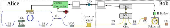
LD laser diode, BS beamsplitter, ϕ-mod phase modulator, TDL tunable delay line, VOA variable optical attenuator, Circ circulator, FM Faraday mirror, TDC time to digital converter, SNSPDs superconducting nanowire single photon detectors.
To compensate for the relative phase drift between the transmitter and receiver interferometers, we implemented a control system based on a Peltier cell, acting on the receiver. The fiber’s delay line loop at the receiver is mounted on one of the faces of the Peltier. The device slightly changes the temperature of one of the receiver’s interferometer arm, changing the refractive index of the optical fiber and, thus, changing the phase. The receiver side computer controls a H-bridge circuit that delivers the appropriate current to the Peltier cell. The control logic is accomplished by a gradient descent algorithm which aims to maximize the measured ER of the control state (leftvert -rightrangle), by applying a proportional and derivative correction to the Peltier current.
The entire optical receiver was enclosed in a box to provide the best possible thermal insulation from the environment.
Temporal reference sharing and synchronizaion is performed by Qubit4sync algorithm33, which employes the same qubits for synchronizing the devices, avoiding the use of an additional, dedicated hardware. Bob recovers indeed the signal period directly from the arrival times of Alice’s qubits, while the initial delay is determined by cross-correlating Bob’s signal with a synchronization string, sent by Alice at the beginning of the transmission.
The real-time QKD postprocessing was achieved by using an adapted version of the AIT QKD R10 software suite34, revised according to the finite-key analysis in ref. 19, which gives the secret key length l
where ({s}_{Z,0}^{l}) and ({s}_{Z,1}^{l}) are the lower bounds respectively on the vacuum and single-photon detection events, h( ⋅ ) is the binary entropy function, ({phi }_{Z}^{u}) is the upper bound on the phase error rate, λEC is the number of bits revealed during the error correction step and ϵsec and ϵcorr are the secrecy and correctness parameter, respectively.
We report the secret key rate (SKR) and the QBER achieved from 1 h of run in Figs. 7 and 8 respectively, while Table 2 summarizes the average values of the live demo, including also the detection rate. QBER in the ({mathcal{Z}}) basis is estimated on average as low as 0.027%; moreover, with a standard deviation of 0.012%, it exhibits an excellent stability, remaining within one standard deviation from its mean for the entire acquisition. We emphasizes that the great consistency of the results is achieved without any active control on the encoder, which is replaced by the self-compensation provided by the Sagnac loop. The control basis shows one order of magnitude higher mean QBER, i.e.,0.23 ± 0.29%, anyway still below 1% on average. This is due to the high sensitivity of interferometers to environmental changes and the slow response of the temperature-based control system, as highlighted by the sharp peaks in the QBER time evolution (Fig. 8, down). The different behavior over time of the QBERs in the two bases is pointed out also by their distributions represented in Fig. 9. QBER ({mathcal{Z}}) is en fact almost normal distributed around its average, whereas QBER ({mathcal{X}}) distribution shows an asymmetric tail extending toward higher QBER values. Nevertheless, the intrinsic reliability of the encoder allowed to achieve a SKR 19.27 kbps, with less than 8% fluctuations.
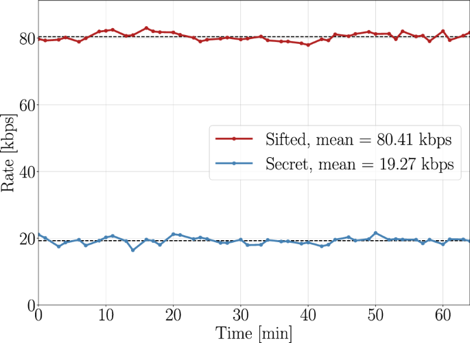
Secret key rate (blue) and sifted key (red) in the experiment.
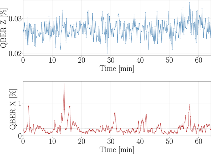
QBER in the ({mathcal{Z}}) basis (blue) and in the ({mathcal{X}}) basis (red) in the experiment.
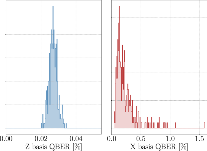
Distribution of the QBER in the ({mathcal{Z}}) basis (blue) and in the ({mathcal{X}}) basis (red) in the experiment.
The low QBER in the key basis, which is independent of the receiver interferometer, constitutes the most relevant achievement of this work, as it certifies the inherent capabilities of the MacZac. The corresponding values results more than one magnitude lower with respect to recent time-bin experiments35,36, also exploiting Sagnac-based design13, and integrated photonic solutions15,16,26,37.
Discussion
In this work we propose an optical scheme, the MacZac, based on the Sagnac and Mach-Zehnder interferometers, for the generation of time-bin states of arbitrary dimensions and mean number of photons. Such device significantly simplifies the transmitter design in a time-bin QKD experiment, by embedding in a single topology both the state preparation and the intensity modulation for the decoy state protocol. The capabilities of the proposed setup have been experimentally verified by means of an all-fiber system producing two-dimensional states. Remarkably, the intrinsic QBER of the encoder has been measured lower than 2 × 10⁻⁵, without requiring for any compensation and initial calibration. This result is unprecedented, being the lowest reported in the literature11,31 to our knowledge. The designed transmitter is applied to a QKD system to perform a real-time demonstration, in a laboratory environment, of the 3-states 1-decoy efficient BB84 protocol. On average, secret keys were generated at a rate of more than 19kbps with a preparation rate of 10 MHz. The proposed transmitter demonstrated noteworthy performances in terms of key basis QBER, measured 0.027% with a standard deviation of 0.012%, direct consequence of the high stability and extinction of the encoder. At the receiver side, the control basis was measured by an unbalanced Faraday-Michelson interferometer, in which the phase compensation is provided by a Peltier cell in order to minimize the receiver’s losses. This method allowed us to achieve a low average QBER of 0.225% for all the duration of the experiment. We think that this scheme might be useful in practical QKD apparatus, given the extremely low QBER, and the possibility to implement it with various technologies, such as discrete fiber components or a single, integrated, photonic chip, that guarantees stability and compactness.
This work opens up to future investigations in the use of the same architecture, by increasing the dimensionality and the transmission rate, in order to achieve higher key rate for a practical secure communication.
Methods
Qudit generalization
The two-dimensional case described above can be generalized for the generation of d-dimensional states, by increasing the number of arms in the Mach-Zehnder interferometer to d. For instance, the design with d = 4 is shown in Fig. 10.
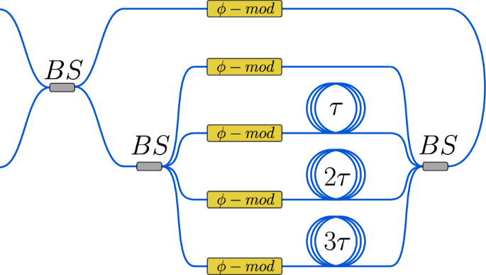
BS Beamsplitter, ϕ-mod phase modulator.
Assuming BS splitting as 50/50, the complex amplitude of the transmitted light in the k-th time slot can be written in the form of Eq. (10)
while the corresponding transmittance is given in Eq. (11)
The d-arm interferometer requires BSs with at least d + 1 ports, one input and d outputs. If not available, the latter device can be replaced by a cascade of standard BSs, as shown in Figs. 11, 12).

a Using a series of two interferometers, b Using two interferometers in parallel. BS Beamsplitter, ϕ-mod phase modulator.
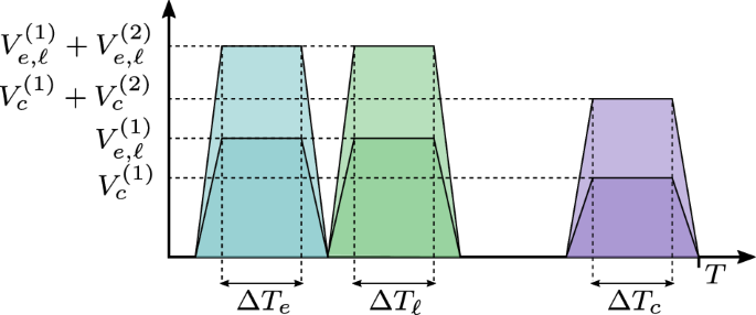
Graph of the signals generated by the digital to analog converter used to drive the phase modulator in the experiment.
The main advantages of the proposed setups are the simplicity and scalability, as the structure can be extended to generate arbitrary dimension time-bin states. In this configuration, it is sufficient to apply an adequate electrical signal when the component that must be modulated crosses the associated modulator. Moreover, the design allows to decrease to one the number of phase modulators, provided that the bandwidth of the single phase modulator is sufficient to act separately on the d time bins. The maximum delay between the temporal modes must be less than the laser pulses’ period. Furthermore, if we do not allow more pulses to be modulated in the loop, the maximum delay added to the propagation time in the loop must be less than the period.
Control electronics
The control electronics is composed by two parts: a commercial FPGA based board (ZedBoard by Avnet, based on the Zynq-7000 SoC) and a custom DAC, developed in our lab and controlled by the FPGA. The block diagram is depicted in Fig. 13.
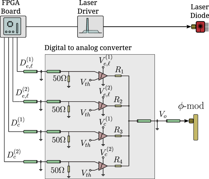
Electrical scheme of the used DAC.
We use four digital outputs of the FPGA, called here ({D}_{e,ell }^{(1)}), ({D}_{e,ell }^{(2)}), ({D}_{c}^{(1)}) and ({D}_{c}^{(2)}), the first two for the generation of (leftvert Erightrangle) and (leftvert Lrightrangle) states, and the other two for the generation of the (leftvert -rightrangle) state. To produce (leftvert E,mu rightrangle) (early with high decoy value) the FPGA generates a pulse at the time TE, i.e., the instant in which early light travels through the phase modulator, on both ({D}_{e,ell }^{(1)}) and ({D}_{e,ell }^{(2)}) digital outputs. This signal triggers the two comparators 1 and 2, whose outputs are then added by the passive resistive network. On the other hand, to generate (leftvert E,nu rightrangle) (early with low decoy value), only ({D}_{e,ell }^{(1)}) fires an output. This strategy provides the two electrical pulse amplitudes needed, which can be tuned by changing the comparators supply voltages.
The same holds for (leftvert L,mu rightrangle) and (leftvert L,nu rightrangle) states, with the only difference that signals are applied at the time TL, which is shifted from TE of the temporal distance between the time bin state, that is 10ns in the case of our experiment. The other two channels are used to control the generation of the (leftvert -,mu rightrangle) and (leftvert -,nu rightrangle) states, hence the timing of those pulses corresponds to T−, i.e., the time in which the optical pulse travels the phase modulator before entering the Mach-Zehnder interferometer. Also in this case the supply voltages are tuned in order to have the same average amount of photons μ and ν, equal to those of the early or late state. The electronics operation is summarized in Table 3.
For what concern the laser driving electronics, the FPGA board provides a 10MHz square signal, that triggers a pulse generator, whose output is sent to the laser diode module.
Model of imperfections
In the proposed scheme discussed in the maintext calculations are made assuming all the BSs to be ideal, so having a splitting ratio (T=R=frac{1}{2}). Real devices present natural discrepancies from this value. Here the effect is quantified.
With reference to Fig. 10, we label the transmittance of BS i as Ti, with the associated reflectance Ri = 1 − Ti. Given an input complex amplitude E0 at the input port of BS1, the amplitudes entering the loop in the CW and CCW modes have the amplitudes
After traveling the loop, the effects of the phase modulators and the unbalanced interferometer leads to amplitudes, of the early (e) and late (ℓ) pulses in the CW and CCW modes, shown in Eq. (13a).
where ϕs is phase accumulated in the Sagnac loop. Recombining at input beamsplitter BS1, early and late components amplitudes are the one reported in Eq. (14a).
The corresponding associated transmittances are the in Eq. (15a).
From this it is possible to identify the effect of the non-ideality of the two BSs composing the interferometer as an unbalance in the maximum transmittance of the two time slots. This can introduce an asymmetry when creating states in the superposition of (leftvert Erightrangle) and (leftvert Lrightrangle). The unbalance, if non-negligible, can be corrected by introducing a certain amount of attenuation in one of the two Mach-Zehnder interferometer arms. It’s worth noting that the phase ϕs accumulated in the Sagnac loop by CW and CCW e (ℓ) states is independent on the propagation direction in the loop, so this global phase does not affect T(e) (T(l)).
The performances of the proposed scheme, in terms of fidelity in the prepared state in the ({leftvert Erightrangle ,leftvert Lrightrangle }) basis, depends instead on the splitting ratio T1 of BS1. The effect can be quantified by looking at the device transmittance when no modulation is applied. Ideally it is zero, an became nonzero for any value of ({T}_{1}ne frac{1}{2}). When preparing the (leftvert Erightrangle) or (leftvert Lrightrangle) states, the device has to transmit the maximum amount of light in one of the time slots, while completely blocking the light from passing in the other. Assuming here BS2 and BS3 to be ideal, the maximum transmittance as function of T1 is expressed by equal to ({T}_{max}=frac{1}{4}) for any value of T1, resulting from the transmittance expression of Eq. (15a) putting ({phi }_{c}-{phi }_{e}=frac{pi }{2}). The minimum transmittance, i.e., for ϕc − ϕe = 0, results instead to be
From those, the minimum QBER that can be achieved is
The minimum transmittance Tmin and the minimum QBER as function of the input BS transmittivity T1 is shown in Fig. 14. In the figure we show the QBER reported is the present experiments by an horizontal dashed line: transmittivity T1 values in the range [0.498, 0.502] allow to achieve QBERmin ≤ 1.5 × 10⁻⁵. Therefore, the reported ultra-low intrinsic QBER does not requires 10−5 precision in the BS splitting ratio: indeed the reported range [0.498, 0.502] corresponds to an error of 0.4% with respect to the nominal 50/50 splitting ratio.
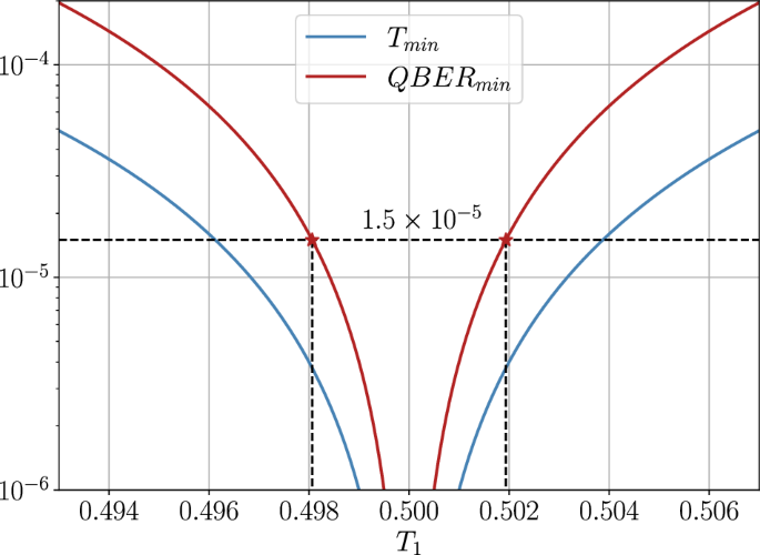
T1 values in between [0.498, 0.502] allow to achieve QBER({atop min}le 1.5times 1{0}^{-5}).
Responses