Noncollinear spin texture-driven torque in deterministic spin–orbit torque-induced magnetization switching

Introduction
Electrical manipulation of magnetization dynamics has emerged as a promising method for the development of spintronic logic and data storage. Manipulation of magnetization using spin current absorption via spin–orbit interaction, the so-called spin–orbit torque (SOT), is attracting great interest for magnetization switching, especially in perpendicularly magnetized systems, owing to its superior benefits of fast switching speed and efficient power consumption1,2,3,4,5,6,7. Despite these advantages, one of the challenges in designing SOT-based devices is the requirement of lateral symmetry breaking and/or an additional z-directional torque contribution (τz) for deterministic magnetization switching in a perpendicularly magnetized system. Applying an external magnetic field parallel to the electric current in SOT-induced magnetization switching, which is a commonly used method to exert the additional τz8,9, is not recommended for practical device applications. Therefore, numerous studies on external magnetic field-free magnetization switching have investigated the various physical phenomena, such as the exchange bias induced by the antiferromagnetic layer10,11,12,13, competing spin current layer14, magnetic tri-layer15,16, tilted magnetic anisotropy17,18,19,20,21,22,23, structural asymmetry24,25, and Rashba symmetry breaking26 by engineering materials and devices.
Magnetic chirality is a manifestation of the broken spatial inversion symmetry in a magnetic system, which determines the characteristic clockwise or anticlockwise spin canting direction. Recently, it has been reported that field-free magnetization switching induced by SOT can be achieved by utilizing chiral magnetic structures, such as magnetically coupled nanomagnets27, magnetic anisotropy gradients28, and the slab geometry of ferromagnetic layers29, extending this approach to utilize magnetic chirality for magnetization switching. Moreover, the distinct z-directional hysteresis loop shift observed in systems involving noncollinear spin texture (NST) reinforces the robust connection between NST and field-free SOT-induced magnetization switching30. Despite many the key direct and indirect experiments for suggesting the possibility of field-free magnetization switching in the chiral magnetic structure, the elucidation of the underlying origin is at a phenomenological level, where the interfacial Dzyaloshinskii–Moriya interaction (DMI)-induced NST is involved. Therefore, a theoretical investigation of the SOT-induced magnetization switching dynamics in NST is helpful for revealing the fundamental mechanism of field-free magnetization switching.
In this report, we suggest that τz is provoked by the DMI in NST. To implement and quantify the NST state, we propose a system that consists of two regions with different perpendicular magnetic anisotropy (PMA) energy densities in the lateral direction. The NST is formed in the interarea between two PMA regions by the current-induced SOT. We conducted a micromagnetic simulation by varying the interfacial DMI energy density and the asymmetricity of the PMA. We verify that the τz component, which possesses the opposite sign to the torque to restore magnetization perpendicularly, is present in the NST. To further support our claim, we experimentally realized a two-level PMA system by utilizing helium ion irradiation and observed the modification of the switching current in the laterally asymmetric PMA regions.
Results and discussion
Magnetization switching without an external magnetic field in chiral magnetic structures has been widely reported using various approaches and is known to be phenomenologically related to DMI-induced NST. To reveal the microscopic mechanism of SOT-induced magnetization switching in NST, we conducted a micromagnetic simulations in a two-level PMA system utilizing Mumax331.
Before discussing the details of the simulation, we briefly describe the two-level PMA system. Figure 1 shows a schematic of the two-level PMA system that consists of a heavy metal (HM)/ferromagnetic (FM) bilayer. The dark yellow-colored and bright yellow-colored regions indicate FM layers with large PMA and small PMA, respectively. In the initial states, both ferromagnetic layers are perpendicularly magnetized. When an electric current (Je) is applied along the x-axis, however, a y-polarized spin current ((vec{{J}_{tt s}}={theta }_{{tt SH}},cdot, left(hat{sigma }times vec{{J}_{tt e}}right))) is generated via the spin Hall effect (SHE) in the HM layer. Subsequently, the spin current is absorbed to the adjacent FM layer and exerts a damping-like torque (DLT) (vec{tau }, sim ,hat{m}times (hat{sigma }times hat{m})) on the magnetization of the FM layer. Here, ({theta }_{{tt SH}}), (hat{m}) and (hat{sigma }) are the spin Hall angle of HM, the unit vector of the magnetization, and the orientation of spin polarization, respectively. During Js injection, NST is formed in the interarea between two PMA regions owing to the difference in magnetic anisotropy. After removing Js, an additional τz occurs in the NST, which will be discussed in detail below. τz is dependent on the direction of the applied Je, and a deterministic magnetization switching can be achieved by τz.

Here, the dark yellow region is the region with a higher PMA energy than the bright yellow region, which possesses a lower PMA energy. When Je is injected, Js appears via the SHE, which results in NST near the two-level PMA boundary. According to the sign chirality, negative (positive) torque occurs and results in deterministic switching (or nonswitching) after being off the current.
The simulation conditions are described as follows: a single-layer nanomagnet with a grid size of (800 × 200 × 1) nm3 in the (x, y, z) direction with a unit cell size of (1 × 1 × 1) nm3, a saturation magnetization MS = 1.0 MA/m, an exchange stiffness Aex = 20 pJ/m, a Gilbert damping constant α = 0.01, and an interfacial DMI energy density Dint = 1.5 mJ/m2. We note that the typical material parameters are adopted as previously reported32,33. We then assign two different anisotropy energy densities (KU) in two regions relative to y = 0. The large KU (KUHIGH) and small KU (KULOW) are set to 1.3 MJ/m3 and 0.8 MJ/m3 for y < 0 and y > 0, respectively. We also apply Js with a magnitude of 1.1 × 10¹² A/m2 and a duration of 0.1 ns. Figure 2a shows the spatial distribution of magnetization during Js injection with its dimensions at 0.1 ns after Js onset. We verify that NST is formed near the boundary between two PMA regions because of the different KU values, as shown in the blue region (0 nm < y < 20 nm). We also investigated the time evolution of the z-component of magnetization (mz) in the blue region. Figure 2b, c shows the simulation time dependences of mz under the applied Je along the +x and −x, respectively. mz rapidly decreases as soon as Js is applied and reaches zero after 0.05 ns, implying that the SOT-induced magnetization dynamics are on the sub-ns scale. Remarkably, we verify that mz in NST is reversed from +z to −z after removing Je along +x direction without applying an external magnetic field. Furthermore, such magnetization switching is not manifested for the Je direction along −x. The current direction-dependent magnetization switching is contrary to the stochastic behavior of conventional SOT-induced magnetization switching. Applying Je in the opposite direction switches the spin orientation of Js and thus the sign of the DLT; namely, the chirality of NST is determined by the direction of the electric current flow. This finding suggests the possibility of an additional τz component, which originates from chirality in SOT-induced NST.
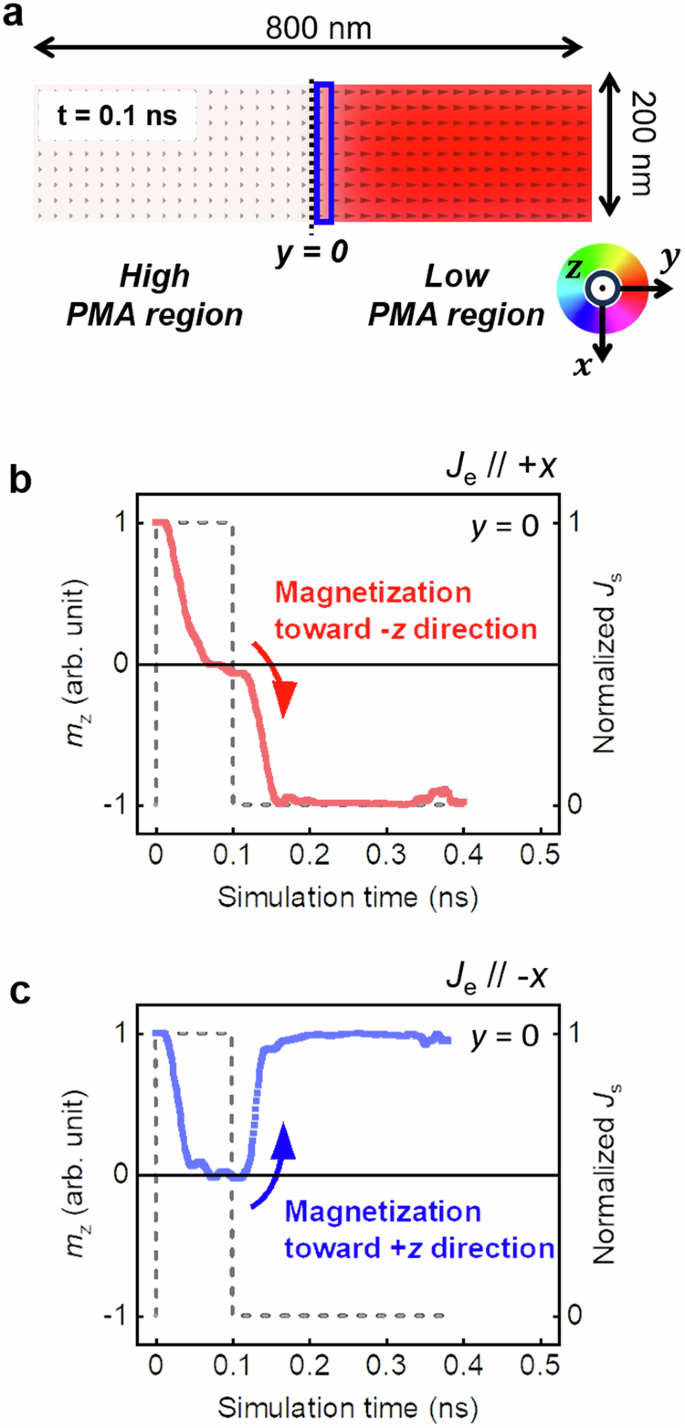
a Magnetization map with system dimensions for simulation and coordination. Here, the small triangles indicate the direction of the magnetizations, and the blue area is the cropped area for the mz dynamics observation. Time-dependent mz for (b) Je//+x and (c) Je//−x. mz dynamics detection occurs near the PMA boundary region, indicated by the blue area. Here, the injected spin current density is 1.1 × 10¹² A/m2 in pulse form, as shown by the gray dashed line.
We now discuss the origin of the current direction-dependent magnetization switching in NST. Figure 3a shows a conceptual schematic of side view of the formation of NST induced by SOT, where Je flows along the x-axis and the y-polarized spin current is absorbed from the bottom HM to the top FM. Considering a steady state by applying a constant current, we subsequently calculate the spatial distribution of magnetization in the two-level PMA regions with the aforementioned physical parameters. Figure 3b–d shows the spatial distributions of mx, my, and mz as a function of the y position. mx and my represent the x component and y component, respectively, of the normalized magnetization. As we expected, DLT induced by spin current absorption results in nonzero my components for both PMA regions. We also note that the mx component is negligible because only the y-polarized spin current is considered and the magnetizations are aligned in the y–z plane. Compared to the region with a large PMA (y < 0), the region with a small PMA (y > 0) shows significant tilting of the magnetization to the y-axis. Notably, we verify that the NST between the two-level PMA regions is formed and stabilized by the current-induced SOT.
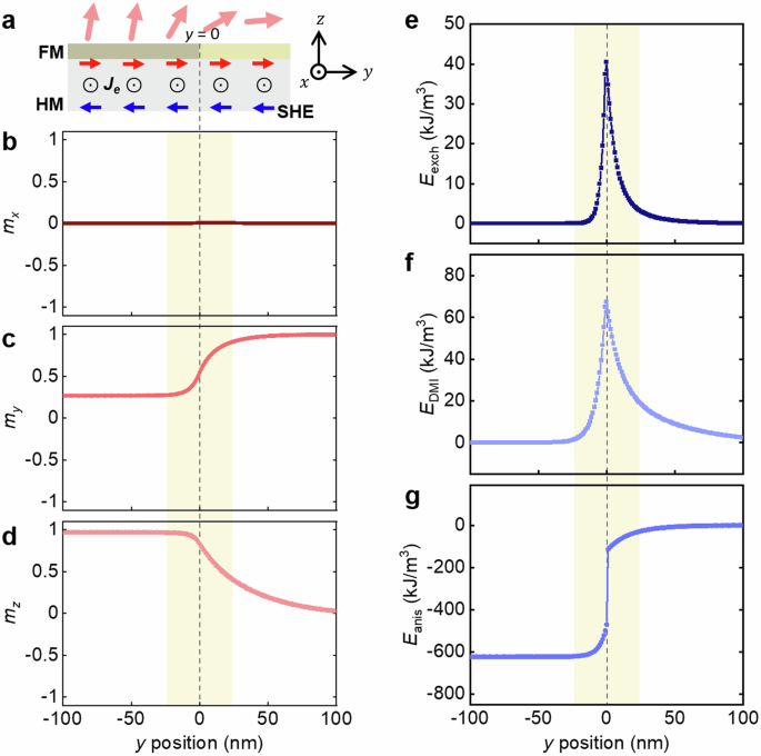
a Schematic of NST by SOT in a two-level PMA system. The y position-dependent magnetization of the b, x-, c, y– and d, z-components. The e exchange energy, f anisotropy energy and g DMI energy of the system are calculated. Here, the yellow regions in b–g indicate the area that has a large energy variation, −25 nm < y < 25 nm.
We now suppose that the current-induced SOT is suddenly cut off. Without current-induced SOT, NST is no longer stable, leading to a dynamic motion of magnetization. The magnetizations are forced to rotate to minimize their energy density, i.e., an effective torque (τeff) is exerted on each magnetization. To estimate how the effective torque acts on the magnetization in the NST, we calculate the total energy density of the magnetic configuration in the two-level PMA regions, considering the exchange energy density (left({E}_{{rm{exch}}}={A}_{{rm{ex}}}left[{left(frac{d{theta }_{{rm{M}}}}{{dy}}right)}^{2}+{sin }^{2}{theta }_{{rm{M}}}{left(frac{d{phi }_{{rm{M}}}}{{dy}}right)}^{2},right]right)), DMI energy density (left({E}_{{rm{DMI}}}={D}_{mathrm{int}}frac{d{theta }_{{rm{M}}}}{{dy}}cos {phi }_{{rm{M}}}right)), and anisotropy energy density (({E}_{{rm{anis}}}={K}_{{rm{U}}}^{{rm{eff}}}{m}_{y}^{2})). Figure 3e–g shows the spatial distributions of Eexch, EDMI, and Eanis, respectively, in the two-level PMA regions under the current-induced SOT, where NST is denoted by a yellow region. Here, θM, ϕM, and ({K}_{{rm{U}}}^{{rm{eff}}}) are the polar angle of magnetization, the azimuthal angle of magnetization, and the effective PMA energy density, including the demagnetization energy density, respectively. In the conventional perpendicularly magnetized layer, the system possesses only Eanis without Eexch or EDMI. In contrast, the nonzero Eexch and EDMI only in the NST region are accounted for by the magnetization distribution of that region. The marked difference in the magnitudes of Eanis between the region with a large PMA (y < 0) and the region with a small PMA (y > 0) is simply attributed to the varying tilting caused by the difference in anisotropy.
The total energy density (Etot = Eexch + EDMI + Eanis) and θM of magnetization in the two-level PMA regions with reversal of Je are displayed as a function of the y position by the black dots and blue dots in Fig. 4a, b, respectively. From the work done by torque, the effective torque is expressed in terms of the changes in the energy density of magnetization and the magnetization configuration: (d{E}_{{rm{tot}}}={vec{tau }}_{{rm{eff}}}cdot d{vec{theta }}_{{rm{M}}}=d{theta }_{{rm{M}}}left({vec{tau }}_{{rm{eff}}}cdot {hat{e}}_{theta }right)), where ({hat{e}}_{theta }) is the unit vector of the polar angle in polar coordinates. Figure 4c, d shows the spatial distributions of the effective torque (τeff = dEtot/dθM) with +Je and −Je, respectively. Surprisingly, the calculated τ eff with +Je, as indicated by the red arrow in Fig. 4c, exhibits a negative torque in the range of 0 ≤ y ≤ 5 nm. This result implies that the negative z-directional torque τz (=τeffsinθM) affects the magnetization and contributes to the magnetization switching in NST. The negative τz is the result of the interplay between the DMI and NST. Intuitively, DMI stabilizes a specific chirality in the magnetic configuration. Immediately after removing the SOT, the NST becomes unstable. A large DMI would then prefer to maintain the NST, while magnetic anisotropy and exchange coupling restore the magnetizations to the perpendicular orientation. In particular, if the direction of the DMI-induced chirality is opposite to the direction of the magnetization restoration, this will result in a negative τeff. Since the chirality of the NST is determined by the spin polarization of the SOT, a negative τeff is not observed under the applied −Je, as shown in Fig. 4d. τeff converges to zero far from the NST region, because spin textures are uniform and collinear due to magnetic anisotropy. We schematically summarize the appearance of the negative τz in Fig. 4e. We argue that a sufficiently large τz enables SOT-induced magnetization switching without an external magnetic field, as shown in Fig. 2b. We also confirm the robustness of the phenomenon we are claiming, recalculating spatial distributions of Etot as a function of θM with different signs of Dint, signs of Je, and initial states (see Supplementary Information Note I).
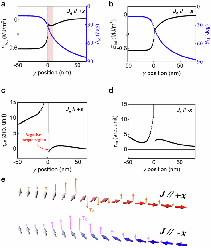
Etot = Eexch + Eanis + EDMI and θM plots as a function of the y position at (a) Je//+x and (b) Je//−x. Negative slope is shown in the red box. The effective torques defined by dEtot/dθM with the y position at (c) Je//+x and (d) Je//−x. The negative sign torque only appears in the Je//+x case, as marked by the red arrow. e Schematics of the spatial distributions of the magnetization and its corresponding τz.
Now, we discuss the relationships of τz with the magnitudes of the spin current density Js, the interfacial DMI energy density Dint, and the difference in the anisotropy energy density between two PMA regions ΔKU (= ΔKUHigh − ΔKULow). Figure 5a shows τz as a function of ΔKU with Dint fixed at 1.0 mJ/m2 and Js varying from 1.0 × 10¹¹ A/m2 to 3.0 × 10¹¹ A/m2. We observe that the negative τz is rapidly enhanced with increasing ΔKU. A large ΔKU and Js give rise to a large difference in SOT-induced magnetization tilting between the two PMA regions, which implies that magnetizations in the interlayer are highly noncollinear. Subsequently, Fig. 5b shows that τz as a function of Dint when fixing Js is 5.0 × 10¹¹ A/m2 and ΔKU is varied from 0.1 MJ/m3 to 0.5 MJ/m3. τz linearly decreases with increasing Dint. Interestingly, a negative τz manifests above a certain Dint. Furthermore, Dint for the manifestation of negative τz decreases with increasing ΔKU, i.e., in a highly noncollinear system. We summarize the trend of τz versus ΔKU and Dint, as shown in the contour map of Fig. 5c. In this contour map, we establish the specific range in which negative τz emerges based on the white region representing τz = 0 while maintaining experimentally feasible ranges of ΔKU and Dint. This serves as a fundamental gauge for assessing whether field-free SOT-induced magnetization switching is achievable. Notably, each limit in Fig. 5c substantiates intriguing physical observations. First, as ΔKU approaches 0, τz ceases to reach negative values. This result is attributed to the diminishing presence of NST as ΔKU diminishes. Consequently, in the absence of NST, all magnetization distributions become uniform, precluding the occurrence of negative torque due to Dint. Second, as ΔKU approaches infinity, the white region approaches Dint = 0. This trend suggests that even in scenarios of extreme NST, where one side’s PMA is much smaller than the other, the sign of τz can be determined by the presence of minute Dint. Furthermore, the depicted or anticipated extreme values in the contour map authentically represent physical phenomena, providing compelling evidence that our simulations accurately depict reasonable physics.
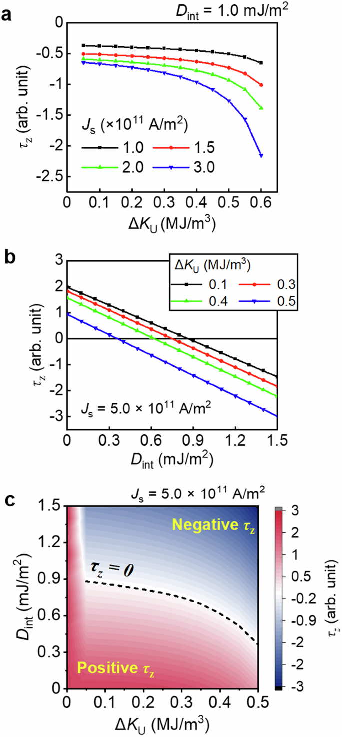
a ΔKU-dependent τz tendency at various Js for a fixed Dint. b Dint and ΔKU-dependent τz and (c) its color map at Js = 0.5 × 10¹² A/m2. The dark dashed curve in the color map indicates τz = 0. Here, τz and ΔKU are defined as ({tau}_{rm{z}}=(d{E}_{rm{tot}}/d{theta }_{rm{M}}),cdot, sin {theta}_{rm{M}}) and (Delta {K}_{rm{U}}={K}_{rm{U}}^{rm{High}}-{K}_{rm{U}}^{rm{Low}}), respectively.
Subsequently, we investigated SOT-induced magnetization switching in the NST region with an assistant magnetic field, which is a common method to achieve deterministic magnetization switching. When a magnetic field is applied in the entire system, the Zeeman energy contribution, described by the equation ({E}_{{rm{Z}}}=-{M}_{{rm{s}}},(hat{m},cdot, {mu}_{0}vec{H})), where ({mu}_{0}vec{H}) represents the external magnetic field, must be considered. In simulations, in-plane directional assistant magnetic field (μ0Hx) aligned either parallelly or antiparallelly with Je is applied. It results in a simplified form of Zeeman energy: ({E}_{{rm{Z}}}=-{M}_{{rm{s}}}{m}_{x}{mu}_{0}{H}_{x}). Etot is calculated as a sum of Eexch, EDMI, Eanis, and EZ. Figure 6a illustrates Etot at μ0Hx of 50, 0, and −50 mT. A noticeable increase in the negative slope at μ0Hx = 50 mT compared to 0 mT indicates a more pronounced assistant effect in negative τz, which diminishes as μ0Hx goes to −50 mT. Afterwards, we calculated the τeff as shown in Fig. 6b. From the results of calculated τeff, it is evident that there is a transition of sign of τeff when μ0Hx is changing from −50 mT to 50 mT, implying that positive μ0Hx assists the negative torque in magnetization switching. We stress that effective zero torque is manifested in non-zero μ0Hx due to NST-induced torque. For a deeper understanding, we investigated τz across various ΔKU values, as depicted in Fig. 6c. In conclusion, we observed that in the NST system, τz gradually shifts towards the negative direction not only with increasing ΔKU but also with larger values of μ0Hx. This aligns with the well-established understanding that a positive μ0Hx assists in deterministic SOT-induced magnetization switching, while a negative μ0Hx induces deterministic non-switching9. Therefore, it is clear that we can achieve smaller switching currents by using larger ΔKU and μ0Hx. Our results also show that as ΔKU increases, the overall trend of τz versus μ0Hx shifts.
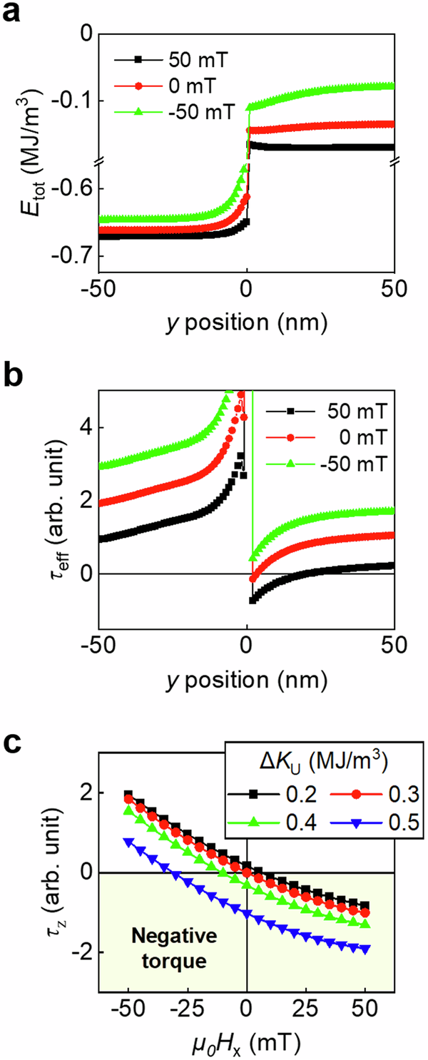
a Calculated total energy and (b) effective torque at μ0Hx = 50, 0, and −50 mT when ΔKU = 0.5 MJ/m3. c Calculated z-component torques in various anisotropy field differences. Here, all of simulations are conducted under condition of Je // +x and Dint = 0.75 mJ/m2.
Finally, we provide experimental evidence of τz in the two-level PMA system. We prepared the Hall bar devices consisting of Ta (3 nm)/Pt (5 nm)/Co (0.8 nm)/MgO (2 nm)/Ta (2 nm) structures. The film structure is deposited by using DC magnetron sputtering, and the device is fabricated by using conventional photolithography and argon ion milling. To realize the two-level PMA system, helium ion irradiation (HII) was used. Because the accelerated He ion has a large penetration length, it could modulate the physical properties of the thin film. Previous studies reported that HII significantly modifies the magnetic anisotropy with only a small modulation of the resistivity and the interfacial DMI in Pt/Co/MgO structures34,35,36. Local area of the Hall bar devices, as indicated by the red line in Fig. 7a, are exposed to HII at various doses of 15, 30, and 45 ions/nm2. As shown in Fig. 7b, two-level PMA systems with μ0ΔHK = 0.4, 0.5, and 0.7 T are achieved by using HII. A detailed explanation of the changes in the HII-dependent material characteristics and the anisotropy evaluation process are provided in Supplementary Information Note III. Here, ΔHK is defined as (varDelta {H}_{{rm{K}}}equiv {H}_{{rm{K}}}^{{rm{NI}}}-{H}_{{rm{K}}}^{{rm{I}}}), where ({H}_{{rm{K}}}^{{rm{I}}}) and ({H}_{{rm{K}}}^{{rm{NI}}}) are the HK in the irradiated (I) region and the nonirradiated (NI) region, respectively.
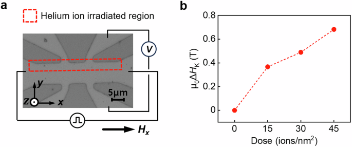
a Optical image of sample for SOT measurements. The red box indicates the HII region which possesses a lower anisotropy than the nonirradiated region. b Difference between ({H}_{{rm{K}}}^{{rm{I}}}) and ({H}_{{rm{K}}}^{{rm{NI}}}) in two PMA areas as a function of HII dose.
We demonstrate SOT-induced magnetization switching in two-level PMA systems. An electric current pulse Je of 5-ms-width is applied with an μ0Hx and the magnetization states are detected by measuring the anomalous Hall resistance. As discussed above, μ0Hx enhances or suppresses negative τz in field-assisted magnetization switching. In other words, asymmetric switching current to a sign of μ0Hx is distinct evidence of τz in the NST region. We first discuss the magnetization switching in the system with μ0ΔHK = 0.7 T. Figure 8a, b displays the magnetization switching with μ0Hx of ±70 mT. Figure 8a, b indicates the switching from magnetization up (+M) to magnetization down (−M) and vice versa, respectively. As predicted by the above calculations, strikingly, we observe that the switching current (JSW) for +M to −M is asymmetric to the current direction. We note that the two-step process of magnetization switching implies that magnetizations in the local area exposed to HII is initially switched and a magnetic domain expands in that area. For the case of switching from −M to +M, JSW is unchanged regardless of the current direction. To confirm the magnetic domain states in the SOT-induced magnetization switching, we used magneto-optical Kerr effect (MOKE) microscopy. The switching from +M to −M initially occurs in the NST of the interarea between two PMA regions and the reversed magnetization subsequently expands by domain wall motion, which corresponds to the two-step process of magnetization switching. However, we identified that the switching from −M to +M begins not from the NST but from the edge area of the sample (see Supplementary Information Note IV). The JSW for the switching from +M to −M is plotted in Fig. 8c, d as a function of the applied μ0Hx. The asymmetry of the JSW to the current direction clearly manifests in all the ranges of μ0Hx. This finding implies that there is a current direction-dependent additional torque component. Moreover, JSW for the switching from −M to +M is kept constant in +JSW and −JSW. Here, we should mention that the behavior of JSW versus μ0Hx could be nonlinear as seen in Fig. 6c, unlike typical SOT-induced magnetization. We subsequently investigated the change in JSW versus μ0ΔHK by fixing the current direction to +Je. As shown in Fig. 8e, f, the JSW for the switching from +M to −M is largely suppressed at high NST, and the JSW for the switching from −M to +M is independent of μ0ΔHK. Given that the beginning of the magnetization switching from −M to +M does not occur in NST, these consistent experimental results strongly support our claim that the additional τz is exerted in NST with a finite DMI. Although the current pulse width of 5 ms is in the thermally assisted switching regime37, we note that the thermal contribution cannot contribute to the asymmetric SOT-induced magnetization switching depending on the current direction.
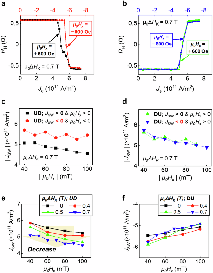
The magnetization is reversed by SOT with the assistance of magnetic fields a, c, e from up to down (UD) and b, d, f from down to up (DU). The up-to-down magnetization switching occurs in the NST, while the down-to-up reversal begins from the sample edge. a, b SOT-induced magnetization switchings under applied assist magnetic fields of +70 mT and −70 mT at μ0ΔHK = 0.7 T. c, d Comparison of |JSW| as a function of μ0Hx with switching the current direction in μ0ΔHK = 0.7 T. Here, the black/green data and red/blue data indicate Je//+x and Je//−x, respectively. e, f Comparison of |JSW| with various μ0ΔHK values at Je//+x. A distinct decreasing trend occurs according to μ0ΔHK as shown by the orange arrow, during UD switching but does not appear during DU switching.
In conclusion, we investigated the additional z-directional torque in DMI-induced NST by simulating SOT-induced manipulation of the magnetization in a two-level PMA system. The exerting direction of τz is dependent on the chirality of NST, which is determined by the direction of the electric current flow. A sufficiently large τz enables SOT-induced magnetization switching without an external magnetic field. Furthermore, we experimentally realized a two-level PMA system by irradiating a part of the HM/FM bilayer with He ions. We observe that SOT-induced magnetization switching is asymmetric to the applied current direction, which supports our claim. We believe that τz can be exploited as a physical parameter to account for the SOT-induced magnetization switching in various systems with magnetic chirality.
Methods
Thin film preparation and device fabrication
We used a magnetron sputter for thin film deposition. The sample structure is Ta(3)/Pt(5)/Co(0.8)/MgO(2)/Ta(2) and the units inside the parentheses are nm. After the deposition, patterning was performed using conventional photolithography and Ar ion etching in the Hall bar geometry. The sample has a width of 10 μm × length of 40 μm in the current line and a width of 3 μm × length of 16 μm in the voltage line.
Helium ion irradiation process
HII can be used as a method to change magnetic properties. The acceleration voltage and beam current are 30 kV and 2.5 ± 0.5 pA, respectively. Here, separate samples were ion irradiated, and the degrees of irradiation were 15, 30, and 45 ions/nm2. The irradiation area was set to 8 µm width × 40 µm length, where ions only pass through half of the sample area (5 µm width × 40 µm length) to avoid misalignment-induced errors. The helium ion microscope that we used for HII is housed at the Institute of Next-Generation Semiconductor Convergence Technology in DGIST, South Korea.


Responses