PIM GPT a hybrid process in memory accelerator for autoregressive transformers

Introduction
Attention-based Transformer models have revolutionized natural language processing (NLP)1. Transformer models including GPT and BERT have demonstrated superior performance in many NLP tasks such as text generation2,3, text classification4,5,6, and machine translation7,8 compared to convolution neural networks (CNNs) or recurrent neural networks (RNNs). GPT in particular has attracted widespread public interest in text generation. GPT is a decoder-only Transformer model that generates context in an autoregressive manner by producing a single token at a time3. The sequential processing feature of GPT, on the other hand, results in notable under-utilization of existing hardware such as the GPU, particularly for small batch inference tasks.
Compared to CNNs, GPT has three main features: (1) extremely large model size, (2) low compute-to-memory-ratio and (3) the computation is autoregressive. As shown in Fig. 1, the GPT3-XL model consists of 1.15 billion parameters9, more than a hundred times higher than common CNNs such as ResNet-1810, while the arithmetic intensity per parameter (ops/parameter) is only 2.1, much lower than that of 48.4 in ResNet-18. These features mean large amounts of data have to be accessed through off-chip memory, while the massive amount of parallel computing units on GPU will be severely under-utilized, resulting in penalties in both performance and energy consumption. In the context of token generation in GPT, self-attention and the feed-forward networks (FFNs) rely on vector-matrix multiplication (VMM) instead of the more GPU-friendly matrix-matrix multiplication used for processing the entire sentences. In addition, these VMM operations are characterized by low data reuse as the weight values in the matrix are employed only once, in contrast to convolution operations where extensive reuse of the same weight is feasible. GPT generates a single token at one time by attending to all previous tokens. Since the self-attention computation is input-dependent, all transformer blocks must be executed in a sequential order. Therefore, CNN accelerators11,12,13,14, which optimize pipeline design to exploit inter-layer parallelism, are not suitable for the autoregressive GPT model.

a Parameter and computation cost comparisons of GPTs and ResNet-18. b Operation/parameter ratios of CNN and GPT models.
Recently, several Transformer accelerators have been proposed to accelerate GPT inference15,16,17. However, these designs generally suffer from the following drawbacks: (1) expensive hardware overhead such as the usage of high-bandwidth memory (HBM) and dense in-memory logic; (2) model customization such as model and token pruning, which will make the architecture less flexible and cause accuracy loss; (3) lack of end-to-end acceleration as most studies only focus on the attention computation and feed-forward layers. Moreover, many existing Transformer accelerators are designed for encoder-only models like BERT, instead of decoder-only models like GPT18,19,20,21,22,23,24.
DRAM-based process-in-memory (PIM) is a promising architecture to accelerate memory-bounded tasks25,26. The high storage capacity of DRAM allows all model parameters to be stored on chip. By integrating computation elements onto the DRAM chip, PIM allows the data to be consumed locally, utilizing high internal bandwidth and minimizing off-chip data movement. In principle, the placement of computation units for multiply-accumulate (MAC) operations can be distributed across various regions, including sub-array, bank, I/O driver and logic die. Among these choices, placing MAC units at the bank level provides a favorable balance between performance, energy consumption and area cost27. Recent PIM developments indeed demonstrate efficient acceleration of MAC operations by integrating computation components at the bank level28,29,30,31.
In this work, we propose PIM-GPT, a complete hardware-software solution for GPT inference acceleration. At the hardware level, PIM-GPT is a hybrid system that includes DRAM-based PIM chips to accelerate VMM near data and an application-specific integrated circuit (ASIC) to support other functions that are too expensive for PIM including necessary non-linear functions, data communication and instructions for the PIM chips. At the software level, mapping scheme is optimized to efficiently support the GPT dataflow. To accommodate the large model size and improve performance, the computation workloads are evenly distributed across available PIM channels and banks to maximize utilization of compute resources and on-chip bandwidth. Compared to existing Transformer accelerators15,16,17, the proposed PIM-GPT supports large GPT models end-to-end without the need of expensive HBM, making it an efficient and practical solution for GPT acceleration. Benchmarking analysis shows the proposed PIM-GPT achieves state-of-the-art speedup and energy efficiency for GPT inference tasks. The main contributions are as follows:
-
We design a hybrid system to accelerate GPT inference end-to-end using PIM with minimal changes to DRAM architecture, making it a practical solution.
-
We propose an optimized mapping scheme that maximizes data locality and distributes workloads across PIM channels and the ASIC to achieve high computation parallelism and efficiency.
-
We analyze the performance, energy efficiency, and sensitivity of the complete system through circuit synthesis and a clock-cycle accurate simulator.
-
PIM-GPT achieves state-of-the-art performance 41 − 137 × , 631 − 1074 × speedup and 123 − 383 × , 320 − 602 × energy efficiency over GPU and CPU baseline, for 8 GPT models with up to 1.4 billion parameters.
Figure 2 illustrates the typical structure of a Transformer model, which uses a self-attention mechanism that captures the relationship between different words in the sentence1. The original Transformer model consists of an encoder and a decoder, both containing N identical transformer blocks. Each block includes a self-attention module and a FFN. Among them, BERT and GPT are the two most popular language models. Different from the encoder-only BERT that processes all input tokens at once2, GPT is a decoder-only model that typically handles a single token at once and generates the next token in a sequential manner by attending to all previous tokens9. Despite the differences, these two models share similar blocks, as shown in Fig. 2.
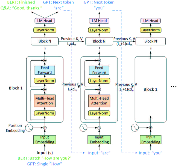
Illustration of the typical structure of a Transformer model, showing the differences between encoder-only BERT and decoder-only GPT.
For GPT, the input token is first transformed into a vector of dimension dm by the input embedding layer, where dm is the feature dimension of the model. The processed token is then fed into the Transformer blocks. The input token is first multiplied with three linear transformation matrices (WK,Q,V) to obtain Query (q), Key (k) and Value (v) vectors, where ({W}_{K}in {{mathbb{R}}}^{{d}_{m}times {d}_{k}}), ({W}_{Q}in {{mathbb{R}}}^{{d}_{m}times {d}_{k}}), ({W}_{V}in {{mathbb{R}}}^{{d}_{m}times {d}_{v}}). The current Key and Value vectors k, v are then concatenated to the Key, Value matrices from the previous inputs. The q vector and Key, Value matrices are then passed to the self-attention heads to capture the dependencies between tokens with the following equation:
To allow the model to learn different relationships for each token, the multi-head attention technique is adopted. The input vectors are split across attention heads, and each chunk goes through a separate head in parallel. All head outputs are combined by a linear projection layer to produce the final attention output. Following the multi-head attention, the attention output is fed into the FFN, which consists of two fully-connected layers with Gaussian Error Linear Unit (GELU) activation function32 in between. The output from the attention block is then applied as inputs to the next block for subsequent processing, repeating through N attention blocks. Afterwards, a final output layer predicts the next token. The content is generated autoregressively by repeating this process until reaches the required token length.
BERT processes all input tokens in parallel and produces the outputs at once. Its core computation is matrix-matrix multiplication, and the performance is typically computation-bounded. In contrast, the core computation of autoregressive models such as GPT is the much lighter VMM in both multi-head attention and FFN layers. As a result, the arithmetic intensity of GPT is relatively low but the required memory access is high. As a result, compute-dense architectures such as GPUs are not efficient for GPT inference, while PIM techniques that leverage the high internal bandwidth of DRAM chips are promising for GPT acceleration.
DRAM-based PIM architectures are promising candidates since DRAM is the mainstream memory in today’s computing systems. The DRAM bank is a two-dimensional array of memory cells with a 1T1C structure, as shown in the inset of Fig. 3c. The cell represents the binary values of “1” or “0” by the presence or absence of charge. When reading data from a DRAM bank, the wordline will be activated and the data stream from an entire row will be offloaded to the row buffer. Employing computation units to directly access and consume data in the row buffer is very efficient. However, the DRAM fabrication process is highly constrained. It only contains three metal layers that severely limit the complexity of the circuit, and the transistors are 3 × slower than those in logic chips at the same node33,34. Therefore, only limited logic and buffers can be integrated on DRAM-based PIM.
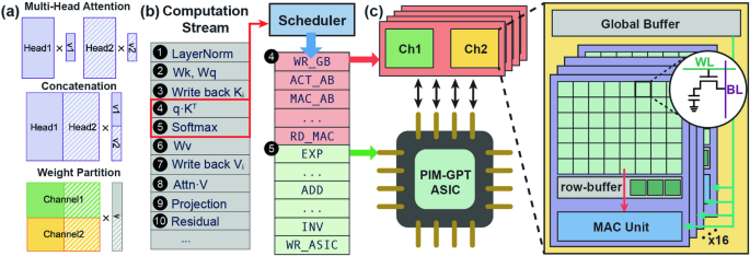
a Hardware-aware GPT model partition. b Compilation of computation stream to command stream. c A complete PIM-GPT hardware architecture.
DRAM-based PIM can be divided into (1) process-using-memory (PUM) and (2) process-near-memory (PNM). The first approach supports computing in DRAM banks or subarrays. It can yield a higher level of parallelism and less data movement. However, to enable in-bank computation, extensive modifications to the subarray architecture are needed35,36,37. In addition, only a limited instruction set is supported. The second approach implements computation logic near DRAM banks and can take advantage of the large internal bandwidth28,30. By balancing the computation logic design and bank organization, PNM-based PIM can achieve both high performance and energy efficiency.
Throughput-optimized processors like GPUs do not effectively accelerate autoregressive token generation due to the memory-bounded and sequential feature of decoders, particularly for inference tasks without batching. These architectures suffer from intensive data transfer of large weight matrices, where the off-die data movement and DRAM interface have a significant energy consumption overhead38,39. Earlier PIM implementations focus on VMM acceleration in neural networks. But inter-layer functions in GPT such as LayerNorm and Residual can contribute ~ 10% of total latency16. Hence, efficient end-to-end PIM acceleration of GPT inference is of high interest.
PIM is a promising approach to relieve the memory bottleneck by storing the matrix and performing VMM in memory. With weight matrices stationary in memory, only the input and output vectors will be transferred through the DRAM interface. Hence, the memory access complexity can be reduced from ({{{mathcal{O}}}}({n}^{2})) to ({{{mathcal{O}}}}(n)). Considering the high costs of adding logic to DRAM, it is more efficient to execute non-data-intensive operations in a separate chip to achieve efficient end-to-end GPT acceleration. Besides hardware architecture advances, efficient workload distribution and dataflow management are required to fully exploit the high internal bandwidth of PIM. The proposed PIM-GPT is an end-to-end GPT accelerator with practical considerations in hardware implementation.
Results
PIM-GPT architecture overview
PIM-GPT is a memory-centric acceleration system aimed to support Transformer-based autoregressive token generation models including GPT. The PIM-GPT system is shown in Fig. 3, which composes of PIM chips and a custom-designed ASIC. The design principle of PIM is to maximally leverage data locality and parallelism to achieve high system performance and energy efficiency during VMM in attention and FFN. To achieve efficient VMM, PIM-GPT strategically partitions the model, taking hardware resources into account. It achieves parallel computing by broadcasting a single vector and reducing instruction overhead. PIM-GPT employs a specific mapping scheme for the attention mechanism, as shown in Fig. 3a. Weight values from multiple attention heads are concatenated to accommodate the physical capacity of DRAM banks. The concatenated attention matrices, along with weights in FFN layers, are distributed to all channels and banks for parallel operation, following the mapping scheme in Fig. 4, details of which will be elaborated later. PIM-GPT utilizes the mature PIM solution with a MAC unit integrated at a bank, which can be easily adapted from the existing LPDDR427 or GDDR630 design, making it a practical solution. The system integrates 8 channels, each of which executes VMM locally by broadcasting the vector from the buffer and loading matrices from DRAM bank arrays, as shown in Fig. 3c.
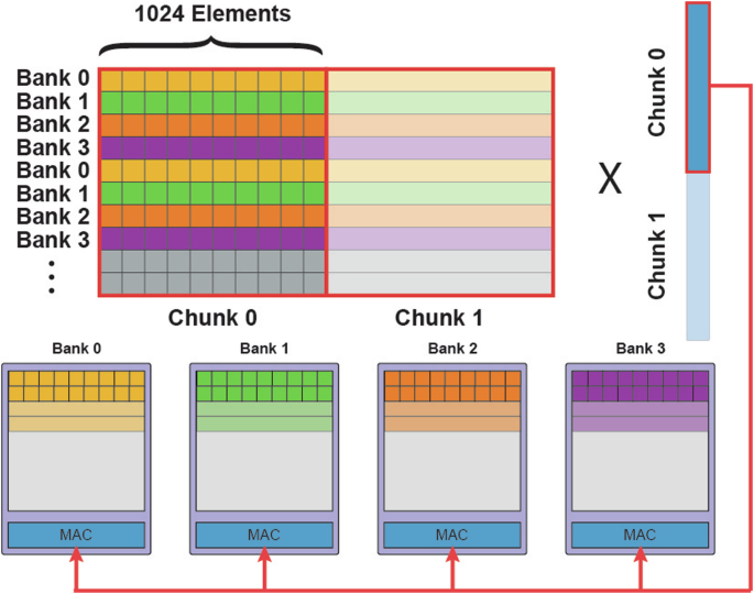
Colors represent the different rows in the original matrix. Rows are distributed across all banks for parallel VMM operation.
A high-level mapping scheme for VMM operation in PIM-GPT is shown in Fig. 4. Since each row of the matrix is multiplied by the same vector, the rows are distributed across all banks. When the VMM begins, the vector is broadcasted to all banks and multiplied with matrix data from each bank in parallel. If the matrix dimension exceeds the physical storage of a bank row, it will be divided into chunks for mapping and computation. Similarly, multi-attention heads are concatenated to a large matrix to utilize parallel computing capability as well as maximize data locality.
To facilitate end-to-end acceleration of large GPT models, non-VMM functions are executed on the ASIC chip. It is essential to highlight that PIM-GPT targets the elimination of off-chip movement of matrix data, requiring only the transfer of input/output vectors between PIM and ASIC for downstream computations, as well as data communication and intermediate data storage. This integration approach leverages the strengths of both PIM and ASIC, optimizing their capabilities to accelerate various computation tasks in the GPT computation stream with minimized data movement between them. Fig. 3b illustrates the compilation of Attention and Softmax to command streams for the PIM and ASIC chips, respectively. The scheduler in Fig. 3b operates as a state machine for computation stream compilation. The sequential computation stream of a Transformer decoder is programmed to the registers. Once the previous computation is complete, the scheduler will send the signal and data for the next computation to start. To initiate a task in the computation stream, the scheduler will compile it to a command stream with the model configuration, which is also programmed to the registers of the scheduler. The command stream will run the basic operations of both DRAM and ASIC, as indicated by red and green color in Fig. 3b, respectively. All data in PIM-GPT are in bfloat16 (BF16) format, which preserves the approximate dynamic range of 32-bit floating point numbers to balance performance and accuracy.
DRAM-based PIM for VMM
Placing MAC units and SRAM buffer inside DRAM modules has been widely used in PIM architectures for machine-learning applications to minimize memory access27,28,30,40. PIM-GPT places the MAC units at every bank. And all 16 banks can perform MAC simultaneously, as shown in Fig. 5a. Such MAC unit arrangement has been proved feasible in both GDDR6 and HBM prototypes28,30. Take GDDR6-based PIM as an example, placing MAC unit per bank offers 512 GB/s peak bandwidth per channel at 1 GHz (256 bits/bank × 16 banks). An SRAM buffer will be used to store and broadcast the input vector. However, integrating large SRAM buffers into DRAM is expensive and impractical. To provide a practical solution of GPT acceleration, we adopt 2 KB buffer size from30, and broadcast vectors to all MAC units for parallel computing. When the input length exceeds the buffer size, vectors will be truncated into chunks, as shown in Figure 4. Partial MAC results will be computed and forwarded to the SRAM on the ASIC, followed by downstream partial sum execution on the ASIC. Compared to writing back to DRAM, forwarding the subportion of VMM results to ASIC reduces overall latency. Eliminating writing back also frees DRAM to perform subsequent VMMs.
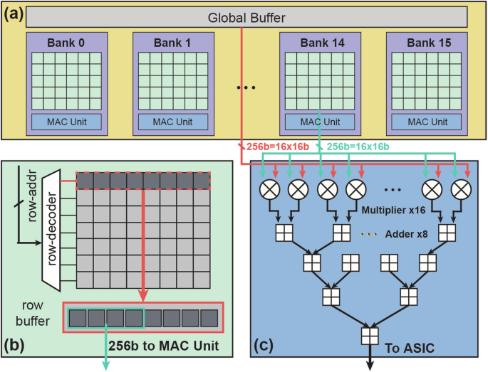
a A channel is composed of a global buffer and 16 banks. A bank contains (b) a conventional DRAM bank and (c) a MAC unit with multipliers and an adder tree.
The bank organization is identical to conventional DRAM architectures, as shown in Fig. 5b. Once a row address is decoded, the entire corresponding row will be activated and all stored data will be forwarded to the row buffer. Herein, if the bank is not closed (precharged), data will be preserved in the row buffer. Reading data from the row buffer is much faster than from the bank array, since it skips the long latency row activation step. Hence, to maximize the utilization of peak internal bandwidth, data should be consumed from the row buffer as extensively as possible. This requires bank scheduling adheres to the open-row policy, wherein a row is not immediately precharged after data access. The goal is to employ this policy and optimally map the model to efficiently consume matrix data. In our mapping scheme, matrix rows for VMM are partitioned and directly mapped to the same row addresses, thereby maximizing the row hit rate, as outlined at a high level in Fig. 4.
Inside each bank, only multipliers and an adder tree are implemented for MAC operation, as shown in Fig. 5c. Similar architecture has been proven effective in prior designs30,40,41. During MAC operation, 16 vector values and the corresponding weights are fetched from the buffer and banks, respectively. The 16 multipliers multiply the vector data with weights. The adder tree accumulates the multiplication results for downstream computation. To minimize hardware cost and improve efficiency, PIM-GPT only performs VMM operations in the PIM while assigning all other computations, such as data bypassing, division and activation functions, to the ASIC. By doing so, the design allows the integration of lightweight MAC units to the DRAM chip to consume data locally without significantly sacrificing the memory capacity.
ASIC architecture
The ASIC in PIM-GPT is used to support non-VMM arithmetic computations, manage data communication and intermediate data storage. The ASIC architecture is shown in Fig. 6. Since VMM operations are performed in the PIM channels, data will only be read from DRAM when a VMM operation is done and requires downstream operations. The PIM channels communicate with the ASIC through memory bus and crossbar interconnects. The interconnects support data fetching from any DRAM channel and sending memory requests to a single channel or broadcasting to all channels after packeting the data with address. Data read from PIM have two possible paths on the ASIC: (1) writing back to banks in other PIM channels, such as Key, Value matrices for subsequent VMM, and (2) going through computation blocks in the ASIC, such as LayerNorm, Softmax, etc.
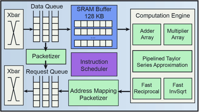
The ASIC supports non-VMM arithmetic computations, data communication, and intermediate data storage.
If the data require downstream computation, they will be temporarily stored in the on-chip SRAM. The computation engines on ASIC are responsible for computations that cannot be run as MACs, such as non-linear activation functions, layer normalization, softmax and partial sum. The adders and multipliers in the computation engines follow the standard floating-point unit design to support summation and multiplication. For design reuse and performance considerations, other computation tasks are implemented with approximation algorithms using only addition and multiplication to achieve the required precision.
Three functions that require approximation are: (1) Softmax (s({x}_{i})=frac{{e}^{{x}_{i}}}{{Sigma }_{j = 1}^{N}{e}^{j}}); (2) LayerNorm (y=frac{x-E[x]}{sqrt{Var[x]+epsilon }}times gamma +beta); (3) GELU((x)=frac{x}{2}times [1+erf(frac{x}{sqrt{2}})]), which can be approximated by (frac{x}{2}times [1+tanh sqrt{2/pi }(x+0.044715times {x}^{3})]).
The nonlinear function ex, (tanh x), division and square root in these functions cannot be naively computed using addition and multiplication. Under given precision and data range, they can be efficiently approximated and converge in rapid iterations. Here ex and (tanh x) are computed using Taylor series approximation with the first six items, which can be computed with addition and multiplication.
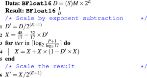
The division operation is computed by multiplying the numerator with the inverse of the denominator. Both the reciprocal and inverse square root operations can be calculated with addition and multiplication following Newton’s method. A proper initial value is required to ensure the fast convergence. For reciprocal, we take advantage of Newton-Raphson division in Algorithm 1. The fast inverse square root algorithm is adopted from Quake III Arena’s source code42, as shown in Algorithm 2.
Algorithm 1
Newton-Raphson Division
Algorithm 2
Fast Inverse Square Root
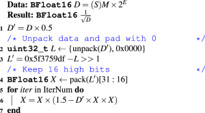
The Newton-Raphson Division algorithm shown in Algorithm 1 is friendly for floating point numbers since it requires the input D to scale to a value close to 0, which can be easily done with exponent subtraction and mantissa shift in floating point data format. The P in line 3 is the precision of P binary places. Hence, for a 16-bit floating point number, it will take three iterations to get an accurate result. The fast inverse square root algorithm in Algorithm 2 unpacks the BF16 data into 16-bit integer data and padding 16-bit zeros to get an accurate approximation, followed by shift and subtraction from a constant. The pack step utilizes the 16 high bits of INT32 (L^{prime}) to assemble a BF16 data’s sign bit, exponent and mantissa. In the fast square root algorithm, it can converge in a single-step iteration. Here we take a conservative two-step iteration.
PIM-GPT dataflow overview
PIM-GPT aims to distribute workloads among all PIM channels and ASIC efficiently. For VMM operation, the input vector is forwarded from the ASIC buffer to the SRAM buffer of all PIM channels, followed by broadcasting to all MAC units, as depicted in Fig. 7. All MAC units will execute MAC of the same vector on different matrix partitions in parallel to fully utilize the PIM computation resources without instruction overhead. PIM-GPT implements the following techniques to coordinate workload between the PIM channels and the ASIC: (1) The partial outputs of VMM can be forwarded to the ASIC before the whole computation is completed, which effectively eliminates the data write back to DRAM banks; (2) When input vector length exceeds the buffer size, SRAM buffer on the ASIC are reserved to store intermediate data and the ASIC will accumulate partial VMM results from DRAM; (3) Pipelining between data transmission and computation, i.e. the ASIC will start operations on partially received vector while the rest are in transmission.
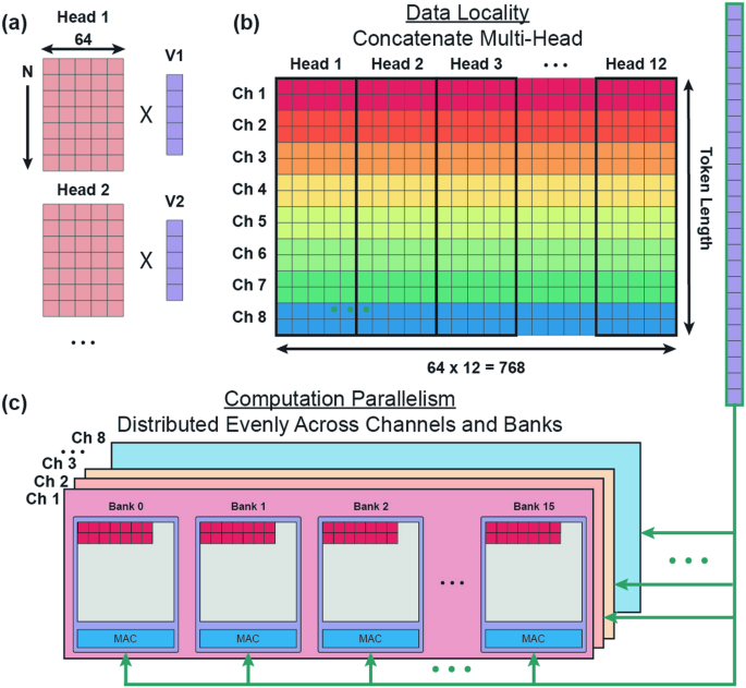
a Multi-head attention. b Concatenating multi-head to exploit data locality. c Distributing weight matrix evenly across channels and banks to maximize computation parallelism.
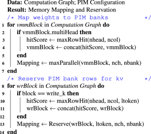
Mapping a model includes storing the weights to the allocated banks, as well as reserving space for the intermediate data (Key, Value matrices) for attention computation since they are dynamically expanded with token generation. To enhance the system performance, the mapping scheme is optimized to: (1) maximize row hit rate by exploiting data locality; (2) increase computational parallelism by balancing the workload across DRAM banks; and (3) reduce latency by minimizing data movement. At runtime, the system computes the bank address in the reserved space to write back Key and Value vectors. The high-level description of the mapping scheme is shown in Algorithm 3.
Algorithm 3
Model Mapping to PIM Banks
Weight mapping methods
As shown in Fig. 7, the mapping scheme leverages data locality and maximizes computation parallelism. Since activation (ACT) and precharge (PRE) commands are expensive in both latency and energy, achieving a high row hit rate is preferred. To this end, matrix data used for MAC operations need to be mapped to consecutive physical DRAM cells. This approach means the corresponding row only needs to be activated once to transfer all required data to the row buffer, and the MAC units can keep consuming data already in the opened row to minimize ACT and PRE operations.
To take advantage of the data locality, it is desired that a row is fully mapped with data. However, a single attention head can be much smaller than the DRAM array dimension. As shown in Fig. 7a, attention head width of GPT2-small is 64 while a bank row can store 1024 16-bit data. To maximize the row hit rate, all attention heads in the same layer are concatenated to fill up the DRAM bank. Take GPT2-small as an example, 12 attention heads are concatenated to form a wider matrix with a width of 768, along with the concatenation of input vectors, as shown in Fig. 7b. The data are mapped as an aligned fashion rather than packed, i.e. map the data to the bank row according to matrix row number. This mapping scheme avoids activating two bank rows sequentially to fetch data in the same matrix row. Hence, the latency penalty induced by bank activation can be minimized. To maximize the utilization of MAC units, rows of the matrix are evenly distributed across PIM channels and banks. Fig. 7c is a detailed example showing how the K matrix is mapped through 8 PIM channels, assuming the token length is 256. First, attention heads in a layer are concatenated along the column direction to form a larger matrix, with a dimension of 256 × 768. The concatenated matrix is mapped following the row-major approach and evenly distributed as 32 matrix rows to each channel, as indicated by the rainbow colors in Fig. 7b, c. Inside each channel, all 16 banks are mapped with 2 rows of the matrix and execute MAC operations with the same vector in parallel. Given that each bank has 16k rows, the V matrix and FFN weights in the decoder block, along with the matrices from further decoder blocks, can be systematically allocated across the rows of successive banks in the same fashion.
Key and Value results need to be written back to the PIM banks and appended to the existing Key and Value matrices. In the mapping stage, PIM-GPT reserves the required space in PIM banks for these intermediate data. Key and Value write-back are in row-major and column-major, respectively, since the transpose of the Key matrix is required in Equation (1), while not for the Value matrix.
PIM-GPT exploits data locality during writing. During a token generation, a Key vector is produced by multi-attention heads, which corresponds to N = 1 in Fig. 7a. The Key vectors with a length of 64 from 12 heads are concatenated to form a vector with a length of 768, and written to the corresponding bank row reserved for the current token. The concatenated Key vectors produced by all token generation steps are evenly stored across all channels and banks for parallel downstream VMM computation. Value results are stored in column-major fashion because transpose is not required. To maximize the computation parallelism in the subsequent VMM, we distribute the Value matrix to all channels and banks using the same mapping scheme for Key matrix mapping as shown in Fig. 7c.
For larger GPT models, widths of both concatenated multi-head matrices and weight matrices in the FFN layers can exceed the capacity of a bank row. In this circumstance, the input vector length also exceeds the buffer size. Hence, both the matrix and the vector need to be truncated for VMM operation, as shown in Fig. 4. The partial VMM results are then accumulated in the ASIC to facilitate pipelined operation. Taking the input length of 2048 in Fig. 4 as an example, the matrix and the vector are sliced into two chunks. The elements in the same row will always be mapped to the same bank, as indicated by the faded color. Computation on the second chunk starts after the first chunk is completed to avoid frequently overwriting the SRAM buffer. The weight matrix tiling scheme distributes matrices evenly to achieve the highest possible DRAM channel-wise and bank-wise MAC computation parallelism.
Discussion
As shown in Fig. 8, the PIM-GPT system achieves remarkable performance improvements, 41 − 137 × speedup over GPU and 639 − 1074 × speedup over CPU for the 8 GPT models. The high speedup originates from three aspects: (1) Memory bottleneck is effectively removed by performing the memory-intensive VMM operations inside PIM channel; (2) The mapping strategy maximizes computation parallelism and data locality; (3) Different workloads are efficiently distributed between PIM and ASIC. In comparison, GPU is not suitable for sequential token generation, since the large memory footprint and low data reuse rate under-utilize the GPU computation resources16.
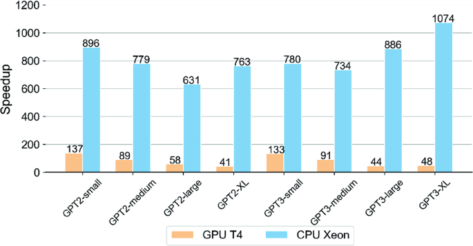
The PIM-GPT system achieves 41 − 137 × speedup over GPU and 639 − 1074 × speedup over CPU for the 8 GPT models.
We also compare the PIM-GPT performance with previously reported Transformer accelerators, as shown in Table 1. SpAtten15 accelerates GPT2-medium by 35 × over GPU, and TransPIM17 obtains similar speedup of 33 × . Both ignore the layer normalization and residual connections in Transformer models. DFX16 provides 3.2 × latency reduction on average. PIM-GPT achieves state-of-the-art performance with 89 × speedup on average over GPU. We also want to highlight that the PIM-GPT testing result is based on 1024 tokens, which cannot be supported by these prior prototypes.
Figure 9 shows that the PIM-GPT achieves energy reduction of 123 − 383 × and 320 − 602 × over GPU and CPU, respectively. PIM-GPT effectively eliminates the energy consumption of DRAM data transmission by using PIM to locally consume data. In addition, the mapping method leverages data locality and minimizes the row ACT and PRE operations that are energy consuming. The ASIC only contributes a very small fraction of the total system energy, but provides highly efficient arithmetic computations.
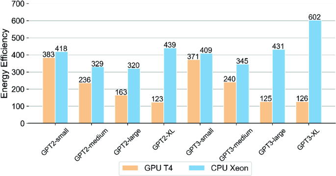
The PIM-GPT achieves energy reduction of 123 − 383 × over GPU and 320 − 602 × over CPU for the 8 GPT models.
In comparison, DFX only achieves 3.99 × higher energy efficiency compared to the GPU baseline16. TransPIM reports ~ 250 × energy reduction17. SpAtten reports 382 × over GPU15, but only the attention layer is included in the energy estimate while others including FFN layers are not considered. Speedup and energy efficiency for the above-mentioned accelerators are summarized in Table 1.
The layerwise latency breakdown of GPT3-small and GPT3-XL in Fig. 10 shows that VMM operations dominate the total execution time of PIM-GPT. All other arithmetic computations only account for 1.16% of total latency in GPT3-XL. For larger Transformer models, the improvement of PIM-GPT over GPU is reduced. This is because larger GPT models allow better utilization of GPU computation resources. As a result, the gain over GPU is reduced when compared with smaller GPT models, although the performance gain ( > 40 × ) is still significant.
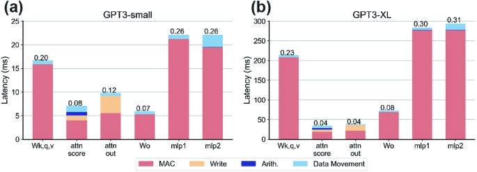
a GPT3-small and (b) GPT3-XL. VMM operations dominate the total execution time.
For PIM-GPT, the VMM computation occurs on the same DRAM chip that stores the required weights and Key, Value mactrices. Therefore, a significant amount of data movement can be eliminated. The data movement only happens when VMM results are transmitted to the ASIC for downstream processing or data synchronization. Figure 11a shows the data transfer reduction can be 110 − 259 × . In PIM-GPT, data movement no longer becomes the bottleneck and consumes a very small proportion of the total latency, as illustrated by the layerwise breakdown in Fig. 10. We also evaluated the reduction of energy consumption of DRAM I/O compared to GPU based on HBM2 and GDDR6 memory, which is commonly used in the state-of-the-art GPUs. The HBM2 access energy 3.9 pJ/bit is adopted from39. PIM-GPT achieves 78 − 184 × and 110 − 259 × I/O energy reduction with respect to HBM2 and GDDR6, as shown in Fig. 11b, proving the effectiveness of PIM-GPT in eliminating external matrix data movement.
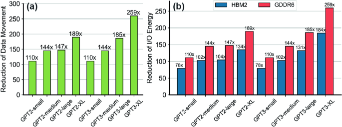
a Reduction of data movement. b Reduction of DRAM I/O energy consumption.
Since weight matrices reside in DRAM, only the input and output vectors will be transferred through the I/O. Hence, the memory access complexity can be reduced from ({{{mathcal{O}}}}({n}^{2})) to ({{{mathcal{O}}}}(n)). As a result, the energy consumption through DRAM I/O in PIM-GPT is less than 10% of total DRAM energy consumption in PIM-GPT, as shown in DRAM energy consumption breakdown in Fig. 12. MAC operation consumes most of the DRAM energy, since VMM is the core part of the GPT. Other DRAM operations, such as ACT, PRE and REF, along with the standby energy consumption consume around 33% of DRAM energy.
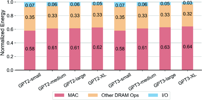
Breakdown of DRAM energy consumption for all models, highlighting the efficiency of PIM-GPT.
In PIM-GPT, data locality is optimized during model mapping to reduce the memory access time and enhance the computation throughput, which is evaluated by the row hit rate. If data is accessed from the row buffer without activating the bank row, such access is a hit. The row hit rate is calculated by the number of hits over total data access. Fig. 13a plots the row hit rates, achieving ~ 98% for the 8 GPT models. The system performance is further enhanced by increasing computation parallelism, as shown in Fig. 13b. More memory channels can be attached to the ASIC with relatively minor modifications to the ASIC data port. The improvement scales almost linearly with the number of channels, proving the efficacy of the parallelism-aware mapping scheme in PIM-GPT. The speedup slightly reduces for longer sequences, because longer sequences require more arithmetic computation on ASIC.
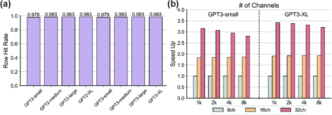
a Row hit rates for the 8 GPT models. b Scalability of PIM channels.
The PIM-GPT ASIC is designed with TSMC 28 nm technology at 1 GHz clock frequency. However, frequency scaling is an important technique for power optimization. We conduct a sensitivity study of ASIC frequency by varying the latency setting in our simulator. Figure 14 shows the latency at different clock frequencies for the 8 GPT models, where the latency is normalized with respect to the 1 GHz results. Overall there is only a small latency increase when the ASIC frequency scales down from 1 GHz to 200 MHz for all models. Even when further scaling the frequency down to 100 MHz, which is 10 times slower than the baseline, the worst case only incurs a performance slowdown of 20%. Moreover, larger models are less sensitive to the ASIC frequency scaling, since their operations are more dominated by VMM and the proportion of ASIC arithmetic computation is less than in smaller models. Therefore, the PIM-GPT design is not sensitive to ASIC clock frequency, which justifies its use where power needs to be optimized by reducing clock frequencies.
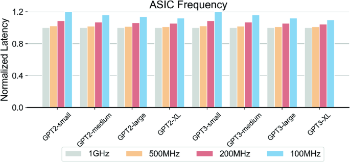
Latency at different clock frequencies for the 8 GPT models, normalized with respect to the 1 GHz results.
The memory interface can be a bottleneck for many computation tasks, even for PIM implementations. In43, SK Hynix reported accelerating fully connected layers in GPT models using GDDR6-PIM system. The system with 4 channels experienced ~ 3 × slowdown when memory interface bandwidth changed from 16 Gb/s/pin to 2 Gb/s/pin. We test the PIM-GPT’s sensitivity to the memory interface by changing the bandwidth configuration in our simulator. Figure 15 shows the latency as a function of memory interface bandwidth for the 8 GPT models. When the memory interface bandwidth changes from 16 Gb/s/pin to 2 Gb/s/pin, the end-to-end GPT inference time is increased ~ 1.5 × on average. That is 2 × better than reported in43, where only VMM and GELU in GPT are considered. Even when the data transfer rate is decreased to 1 Gb/s, all models are slowed down by ~ 2 × on average. These results show PIM-GPT is not sensitive to the memory interface bandwidth, since most data are consumed locally on-chip and the data transfer requirements are significantly reduced.
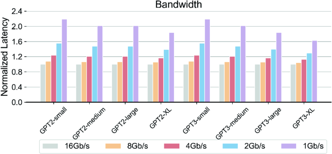
Latency as a function of memory interface bandwidth for the 8 GPT models.
PIM architectures optimize the resolution of memory-bounded tasks by positioning processing units in close proximity to data, leveraging high internal bandwidth. DRAM-based PIM is one of the most promising technologies to accelerate data-intensive computing tasks. Besides research advances, DRAM vendors including Samsung28,29 and SK Hynix30,31 have recently announced DRAM-based PIM technologies. Samsung’s PIM architecture is based on HBM2, which offers 307.2 GBps bandwidth to tackle data-intensive tasks. The design integrates PIM dies on a buffer die with through-silicon vias (TSV). Inside each PIM die, a PU is shared by two banks, operating at 9.6GFLOPS per PU. However, the high costs associated with TSV make this approach less cost-effective. SK Hynix’s GDDR6-based PIM prototype, Accelerator-in-Memory (AiM), supports VMM with a high throughput of 32GFLOPS per PU. But AiM cannot accelerate end-to-end applications standalone due to the limited functions on DRAM chips. Compared to AiM, PIM-GPT limits PIM to only VMM operations and performs the other arithmetic and control functions in a separate ASIC with optimized mapping and dataflow designs to allow efficient end-to-end GPT acceleration.
Recently, several Transformer accelerators have been proposed. Most of them target computation-intensive encoder models18,19,20,21 and are not well-optimized for the memory-bounded GPT. Few works accelerate GPT token generation tasks15,16,17. DFX16 partitions the GPT models to multiple FPGAs to leverage parallel computation but does not reduce the data load/store. SpAtten15 involves algorithmic optimization such as pruning and quantization to reduce memory overhead. However, these methods inevitably reduce the model inference accuracy. And SpAtten only speeds up the attention mechanism in Transformer. TransPIM17 takes advantage of PIM and proposes a token-based dataflow requiring the ring broadcast buffer (2 kb) per bank to store temporary data. The design requires subarray-level modification and extensive on-DRAM data movement. The proposed PIM-GPT requires minimal changes to DRAM and optimizes the workload distribution to achieve fast end-to-end GPT acceleration.
In this work, we propose a complete, hybrid system, PIM-GPT, to accelerate memory-bounded GPT token generation tasks. PIM-GPT consists of PIM chips and a lightweight ASIC to support end-to-end GPT acceleration. Model mapping and workload distribution are optimized to maximize computation parallelism and data locality. The proposed system achieves 41 − 137 × , 631 − 1074 × speedup and 123 − 383 × , 320 − 602 × energy efficiency over GPU and CPU on 8 GPT models by eliminating matrix data movement. We highlight that the design only requires light modifications to the DRAM architecture and thus offers a practical and efficient PIM solution.
Methods
Hardware configuration
To perform realistic estimates, we use GDDR6-based PIM prototype reported from SK Hynix for performance evaluation30. The design only integrates lightweight MAC units near banks. The area of one processing unit (PU) is 0.19 mm230. All logic components of the ASIC are synthesized with SystemVerilog using Synopsys Design Compiler at TSMC 28nm HPC+ process node. Area and power of the logic components are obtained from the synthesis results. The area and power of SRAM buffer are extracted from the TSMC 28nm datasheet based on Synopsys Memory Compiler. The ASIC only consumes a core area of 0.64 mm2, and the peak power is 304.59 mW.
For DRAM energy benchmark analysis, we synthesized the optimized floating-point MAC units at 28 nm technology, followed by scaling the voltage to 1.25 V to match the GDDR6 supply voltage30. Since routing is more complex in DRAM due to the limited metal layers compared to CMOS logic process, we conservatively multiply the power by 1.5, which comes to 149.29 mW for 16 MAC units. As GDDR6 can be fabricated in 1 ynm technology30, the actual power consumption is expected to be lower than this estimate. Table 2 lists the timing constraints and current values used to model the PIM behavior for each command. For PIM related commands, the timing constraints are obtained from30. For normal DRAM commands, we adopt GDDR5 timing constrains in44 to make a conservative estimation due to the lack of detailed information of GDDR6. Similarly, the current values are obtained from DDR5 datasheet45 and multiplied by 3 to account for the current consumption increase during parallel bank operations31. The GDDR6 I/O access energy 5.5 pJ/bit is adopted from GDDR6 datasheet46. The system performance in latency and power efficiency is evaluated based on these conservative assumptions. Detailed hardware configuration is summarized in Table 2.
Simulation configuration
To evaluate the PIM-GPT system performance, we developed an event-driven clock-cycle accurate simulator in C++ that models the system behavior at token generation runtime. The simulator takes the GPT model and system configuration as inputs for model mapping. The computation graph is compiled into an instruction sequence following the hardware constraints.
The PIM and ASIC behaviors are modeled as state machines. The PIM hierarchy is organized as a tree structure at package, channel and bank levels. The PIM package node refers to the entire PIM portion that contains 8 channels as child nodes. Each channel consists of 16 banks as leaves. The state update will traverse down the tree from the root to the leaves. The same organization hierarchy can be found in other memory simulators, such as Ramulator44.
The transition of states follows the timing constraints. At every clock cycle, the simulator checks the status of the ASIC and the PIM package. If both are in Idle state, the current instruction is completely consumed. It then fetches the next instruction, which will be decoded into command sequences. The ASIC chip or the PIM chip will be put into Process state after the instruction is issued. The simulator will compute the time next_time that the ASIC or relevant PIM banks will take to complete the triggered events based on the latency model. The simulator keeps track of the status of all hardware components. If the CLK reaches the next_time, the status of the corresponding node will be changed back to Idle.
Benchmark analysis
The performance and energy efficiency of the proposed PIM-GPT system are evaluated using the simulator and compared to GPU (NVIDIA T4) and CPU (Intel Xeon Gold 6154 with 16Gb DDR4). 4 GPT247 and 4 GPT39 models with up to 1.4 billion parameters are used for the single batch inference benchmark analysis. DRAM energy is evaluated by multiplying the IDD values consumed during each command with the corresponding latency and VDD, following the standard procedure45,48. DRAM refresh operations are also included. The energy consumed by the PIM MAC units and by the ASIC are computed by multiplying the latency reported by the simulator with the synthesized power consumption. The energy consumed through I/O is evaluated by the number of data transferred between the PIM chip and the ASIC chip.
We select NVIDIA T4 as the GPU benchmark as it also uses GDDR6 as memory for a fair comparison. For GPU, latency is recorded using torch.cuda.Event(), and power is measured with pynvml, which is a wrapper around the NVIDIA management library. For CPU characterization, we use python package time.time() for latency measurement and an open-source terminal tool s-tui for power monitor. In each measurement, we generate 1024 tokens and repeat 10 times to report average energy and latency values.
Responses