Rapid karstification process with evaporite-driven sinkholes in Southern Kohat Basin, NW Pakistan

Introduction
Sinkholes are often formed in soluble rocks (evaporites and carbonates) that dissolve at the surface or in the subsurface coupled with the internal erosive and deformational processes1. These processes in karst topographies are influenced mainly by sediment thickness above karst zones, mechanical properties of covering materials, and changes in water table zones2. Evaporitic rocks, such as gypsum and halite, dissolve more rapidly than carbonate rocks due to their inherently higher solubilities and lower mechanical strength, coupled with a ductile rheology3. Therefore, sinkholes often characterize the unique feature in the evaporitic or carbonate-bearing landscapes, which display various sizes and shapes, spanning from a few to hundreds of meters in diameter and depth4.
The occurrence of sinkholes is considered a significant threat to the lives and properties of nearby communities. Meanwhile, artificial factors, such as groundwater interaction, extraction, and water-leaking infrastructures, will likely cause and accelerate sinkhole formation5,6,7. Ground deformation during sinkhole development may significantly damage infrastructures, including highways8, railway tracks9,10, reservoirs11, channels12, and nuclear plants13. Such damages significantly negatively impact building stability and can result in substantial financial repercussions in various regions of the world11,14.
To mitigate sinkhole-associated hazards, various geophysical technologies have been implemented to identify and monitor sinkholes, such as electrical resistivity tomography (ERT), surface wave inversion, refraction tomography, ground penetrating radar (GPR)15, and airborne LiDAR. These methods can frequently deliver suitable resolutions but are time-consuming and costly and, therefore, not applicable in broad areas16,17,18.
Interferometric Synthetic Aperture Radar (InSAR), an imaging geodetic approach, has been widely used in various applications where high-resolution, millimeter-level deformation mapping is required (e.g.,19,20,21,22). InSAR has been employed to detect and monitor sinkhole subsidence across the world, i.e., in Iran23, Texas24,25,26 and Florida27 of the U.S., Dead Sea shorelines in Israel28,29,30,31,32, Spain33, Quebec City of Canada34, Italy35,36, Turkey37, and China7,14. These results provide thorough spatiotemporal assessments, allowing for mapping and tracing the evolution of sinkholes.
Combining InSAR with ground-based geophysical technologies, some regions suffering from sinkholes are comprehensively investigated. For example, GPR and electrical resistivity were used for mapping sinkholes caused by buried evaporitic rocks in northeast Spain38,39, West-Central Florida40, Colorado Plateau, and Arizona41,42. Seismic refraction and transient electromagnetic methods were used for investigating Nahal Hever sinkholes along the Dead Sea coast43. Surface wave, seismic reflection, geotechnical, gravimetric prospecting, magnetic induction, and photogrammetric approaches were used for evaporitic sinkholes in Italy44,45,46,47. However, most of these studies focus on the subsurface evaporitic environment because sinkholes in these regions are caused by the buried evaporites with few surface expressions.
Kohat basin (Fig. 1c) of the Himalaya foothills records the classical features of Indo-Eurasian collision and Tethys Sea closure48,49. The receding in the Tethys Sea led to the deposition of thick marine evaporites in the Kohat Plateau, along with other sediments from the Miocene to the present50. In the southern Kohat basin, namely the Karak region, the tectonically complex nature of the Kohat fold and thrust belt is characterized by evaporite-driven deformation in the form of sinkholes. These sinkholes are typically fault-controlled because evaporite is emplaced on the ground due to thrusting. Given their highly soluble nature and dissolution activities, evaporites of the Karak region showcase one of the best exposures of karstification landforms. Such extraordinary deformation features form well-developed, salt-dissolution sinkholes that are unique worldwide.

a shows the world elevation map, b the geographical location of Pakistan, and c the tectonic structure of the Kohat Potwar fold and thrust belt. Yellow and pink rectangles show the coverage of the ascending (AT-173) and descending (DT-5) tracks of the Sentinel-1 images. Regional tectonic elements are shown in black lines. PB Peshawar Basin, MBT Main Boundary Thrust, JF Jhelum Fault, HKS Hazara-Kashmir Syntaxis, DF Domeli Fault, DT Diljaba Thrust, SRT Salt Range Thrust, KBF Kalabagh Fault, TIR Trans Indus Ranges, KR Khisore Range, PR Pezu Ranges, BF Bahadarkhel Fault, KF Karak Fault, KF Kurram Fault (b) represents the lithological units of the study area as indicated by the red frame in (a).
Because saline water dominates the hydrological system, freshwater only exists in small pockets with aquifers varying from 3 m to 90 m depth in this region51. Rainfall is regarded as the primary source of groundwater recharging, although small dams have been constructed to recharge the aquifers and avoid groundwater depletion in the past decades52. Recently, the groundwater levels have gradually decreased due to the basin’s arid climate and insufficient usage of water reservoirs52. This condition not only concerns the sustainability of water resources but also leads to the formation of sinkholes and land subsidence, which cause socioeconomic damage to the local community. Nevertheless, the distribution of the developing sinkholes is still poorly known. To our knowledge, only one study concerns the sinkholes in this region using a geophysical approach53, which is limited to a very small area.
Here, we implement the time-series InSAR technique to map sinkholes and associated subsidence in the Karak region of southern Kohat Basin, providing the first complete documentation of the spatiotemporal evolution of sinkhole subsidence in a tectonically active, evaporite karst context. Combined with the electrical resistivity profiles, we better understand the linkages between sinkhole development, subsidence, and sub-surface structures. Our study emphasizes understanding the sinkhole development in the surface exposure of evaporites, whereas globally documented sinkholes focus on the subsurface evaporitic environment. We also conduct field-based validations with resistivity profiles and in-situ investigation. The high-resolution deformation derived from InSAR with field investigations shed new light on characterizing evaporite-driven sinkholes based on their forming mechanisms with the geological structures. The results also provide an essential dataset to mitigate the associated hazards for this less-representative community.
Geology of the Kohat basin
Geologically, the continuous collision of the Indian and Asian plates in Cretaceous-Eocene time resulted in the western Himalayan Foreland and Fold and Thrust Belts, directly representing the active Himalayan orogeny54. Kohat and Potwar fold and thrust region situated between the Main Boundary Thrust (MBT) and the Salt Range Thrust (SRT), is a classical feature of the fold-and-thrust belt of Himalaya orogeny55 (Fig. 2a). The study area is located in the Kohat Fold and Thrust Belt, i.e., the southern part of Kohat Basin, and is bounded by regional fault system, i.e., Surghar Range Thrust in the south, Main Boundary Thrust (MBT) in the north, Jhelum Fault in the east, and the Kurram Fault in the west56 (Fig. 1c). This intermontane basin hosts a sedimentary succession of Paleocene to Pliocene age Siwalik rocks, and basin fill sediments including alluvial plains and flood plains57 (Fig. 2b). Siwalik rocks (Murree Formation, Kamlial Formation, Chinji Formation and Dhok Pathan Formation) comprises of the sandstone, clays, shale and conglomerates (Fig. 2b). Karak Fault is a major thrust in southern Kohat places Eocene evaporites (Bahadarkhel Salt and Jatta Gypsum) over the Siwalik rocks58,59. The sinkholes are scattered in this evaporitic unit in the Karak region of the southern Kohat Basin.
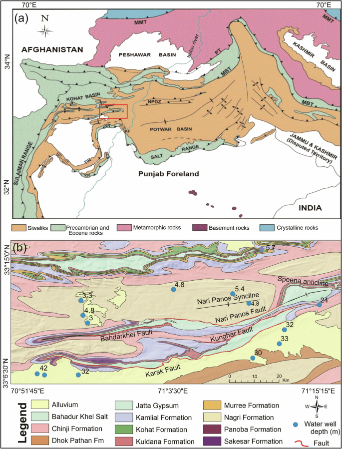
a Regional geological and tectonic elements of the NW Himalayan foreland fold and thrust belt Pakistan (modified from ref. 56), MBT Main Boundary Thrust, PT Panjal thrust. KF Kalabagh Fault, SR Surghar Ranges, NPDZ Northern Potwar deformed Zone, and the red inset shows the study area. b Lithological map of the study area (modified from refs. 62,74) with water wells shown as light blue circles, besides which the numbers indicate their depths.
Results
The LOS (Line-of-Sight) and vertical deformation fields provide high-resolution details throughout the targeted area (Figs. 3 and 4a). We divide the area into four zones, i.e., Bahadarkhel area, Nari Panos, Speena Banda, and Tarkha Koi, based on the exposure and distribution of sinkholes. It is evident that the positive Line-of-Sight (LOS) velocities dominate in the study region, indicating the ground moves away from the sensor for both geometries, namely subsidence or eastward/westward motion for ascending/descending tracks. In other words, this consistent deformation pattern suggests that the horizontal motion, particularly the west-east displacements, are much smaller than the vertical displacements. Their similarities in magnitudes and spatial distributions also provide cross-validation for the InSAR measurements, given the lack of ground truth data.
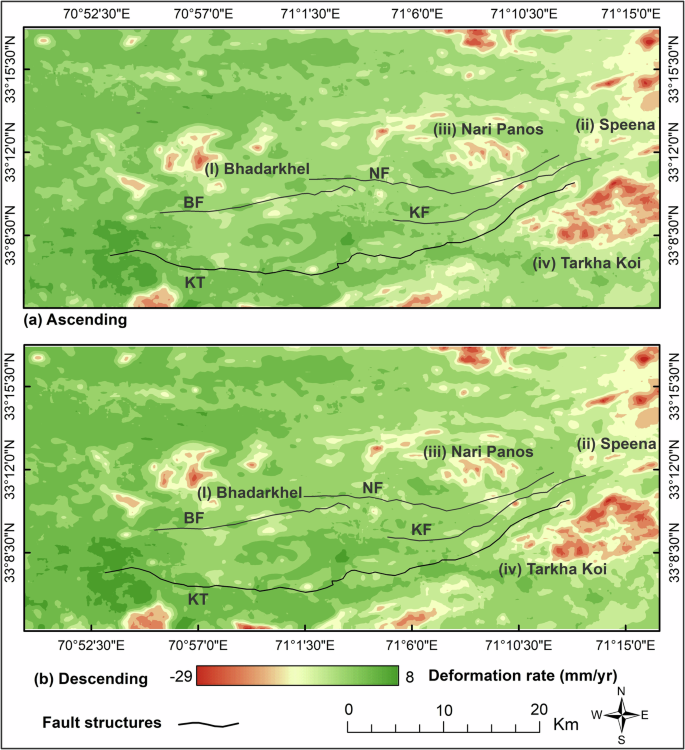
a represents the LOS velocity from the ascending track, and b displays the LOS velocity from the descending track. In the figure, black lines represent the fault structures in the area (BF Bahadarkhel Fault, NF Nari Panos Fault, KF Kunghar Fault, KT Karak Thrust.
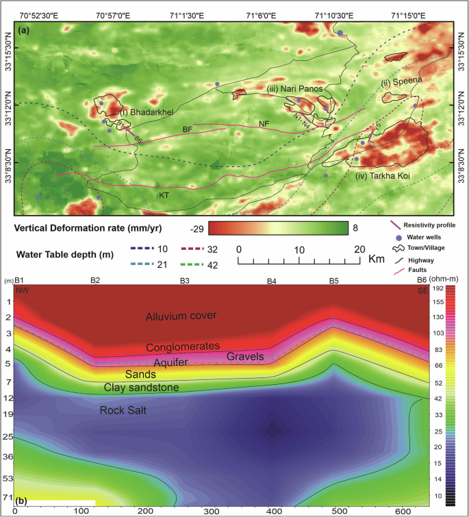
a Vertical velocity map with water depth contours in dash lines. Blue dots represent water wells; black lines represent roads; black line polygon represent rural settlements magenta color represents faults (BF Bahadarkhel fault, KT Karak thrust, NF Nari Panos fault), and purple color lines show the location of resistivity profiles. b Vertical deformation profile of B1-B6 in NW-SE direction. c shows acquired resistivity profile B1-B6 (Bahadarkhel). N1-N4 (Nari Panos) and Y1-Y5 (Tarkha Koi) are shown in Figure S3.
The decomposed vertical deformation map highlights four significant localities with varying characteristics of sinkhole spatial distribution. The Bahadarkhel and Nari Panos regions exhibit high velocities with large-area subsidence. Further to the east, the Speena Banda site exhibits considerable surface subsidence caused by wide and deep sinkholes. Moreover, the highest velocities appear in the Tarkha Koi region (Fig. 4a), with sparse surface deformation in the form of dissolution openings. Aside from these four highly deformed zones, several small areas with localized subsidence reflect the scattered spatial distribution of developing sinkholes throughout the region. Note that our primary focus is on the vertical displacement of sinkholes, which is very localized. Particularly, given the active tectonic in this region, lateral tectonic movement must exist. However, their deformation pattern has different spatial wavelengths with localized subsidence caused by sinkholes. We, therefore, focus our following interpretation on the vertical deformation field.
We evaluate the groundwater distribution and hydrological profiling from water table data and resistivity cross-sections. Groundwater’s volume and pressure may either stabilize or destabilize substrates. Consequently, excessive utilization and dissolution trigger instabilities in the subsurface strata60. We determine six lithological stratas based on true resistivity measurements, namely, alluvial strata, conglomerates, sands, gravels, clayey sandstone, and salt layer. Profile-1 (Bahadarkhel) reveals a decreasing trend in resistivity values from the surface towards the subsurface, reflecting a confined aquifer in sand and gravel at (2.5 to 3.5 m) depth with resistivity values of 52 to 83 Ωm (Fig. 4c). The same startas (gravel and sands) in profile-2 (Nari Panos) region delineates the aquifer at a depth of 20 to 33 m, exhibiting resistivity values ranging from 20 to15 Ωm (Figure S3). Profile-3 (Tarkha Koi) is characterized by resistivity values (150 to 300 Ωm) in unconsolidated sandstone beds and gravel at 40 to 50 m depth, indicating water-saturated beds (Figure S3b).
We examine the relationship between resistivity profiles and groundwater level fluctuation with the InSAR-derived subsidence map. The vertical deformation highlighted in the Bahadarkhel B1-B6 profile (Fig. 4a) reveals the subsidence observed in the cross-sectional profile in the NW-SE direction (Fig. 4b) and is characterized by the downward tilting of alluvial strata, as illustrated in the resistivity profile (Fig. 4c). The shallow water level (2.5 to 3.5 m) and evaporites in the Bahadarkhel region ensure salt rock dissolution (Fig. 4c). The resistivity profile (N1-N4) of the Nari Panos region reflects the SE tilting of shallow subsidence, as shown in the subsidence cross-section (Figure S3d). In the southeast part, i.e., Tarkha Koi (Y1-Y5) profile, an increasing water depth causes a predominant bedrock sagging phenomenon, exhibiting the strata tilting towards the southwest side of the profile (Figure S3d) with a considerable area of subsidence presented in the subsidence profile (Figure S3c).
The resistivity profiles effectively marked the lithological layer, with evidence clearly indicating the tilting of strata, including high- and low-resistivity zones. In addition, the resolution in a vertical resistivity survey decreases with depth, which may lead to overlooking small-scale finer features. However, the large-scale geological features, i.e., the Karak thrust associated with the decollement layer along evaporites, facilitate fault movement with low friction and ductility. Coupled with the Bahadar Khel fault, the Nari Panos fault, and the Nari Panos syncline (Fig. 1b), such fault movement strongly deformed the surficial and shallow surface geological structures, shaping the local fractures and joints that aid in the collapsing of sinkhole subsidence.
The time series of LOS displacements for four selected zones indicate that subsidence occurred consistently from 2015 to 2023 (Fig. 5). We conducted fieldwork in this region in January 2024 and captured deformation signals on the ground surface. Based on InSAR-detected localized deformation and field observations, we categorize Karak sinkholes into three distinct types61: cover collapse sinkholes, bedrock sagging sinkholes, and bedrock collapse sinkholes (Figs. 4 and 5).
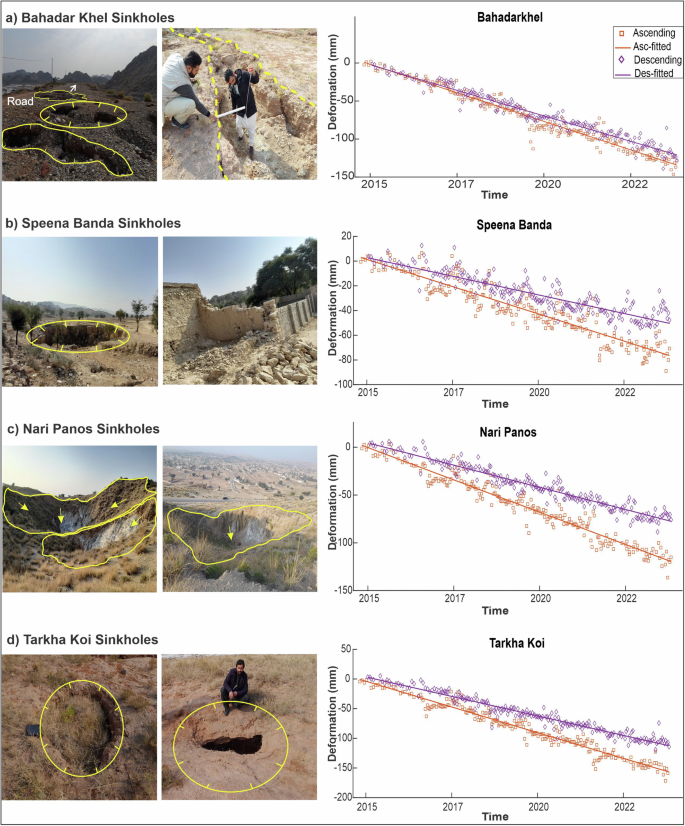
a Bahadarkhel region, cover-collapse sinkholes, the damaged road, and the sinkhole trench. b Speena Banda bedrock-collapse sinkholes with a damaged house. c Cover-collapse sinkhole of Nari Panos. d newly developed dissolutional features of Tarkha Koi bedrock sagging sinkholes.
Cover collapse sinkholes observed along the Bahadarkhel section, about 1 km of the highway that was damaged when passing through the region by karstic features and trenches with a cumulative deformation of −140 mm (Fig. 5a). The development of these sinkholes is mainly controlled by shallow water table depth along with a stream parallel to the Bahadarkhel fault, which exposes the evaporite rocks in this region, with sand and clay acting as an alluvial cover that possesses permeable pathways (Fig. 6). Consequently, water interacts easily with the evaporites on the ground and promotes dissolution, developing extensive sinkholes.
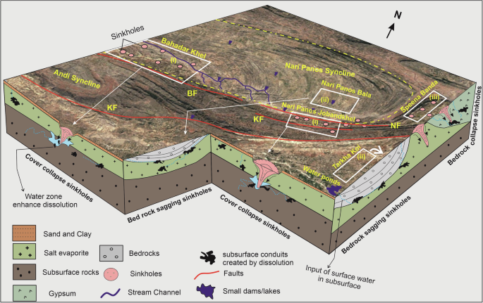
Red lines represent fault structure. KF Karak Fault, BF Bahadarkhel Fault, NF Nari Panos Fault.
Sinkholes detected in the northeast region, i.e., Speena Banda, represent the bedrock collapse phenomenon with small-scale dissolution features to considerable sinkhole exposure. In this region, the bedrock is gypsum, with sand and siltstone as surficial materials, and displays shallow to deep sinkholes. We identified a 40 m deep and 115 m wide sinkhole close to the Speena Banda village (Figure S4). According to historical optical imagery, the sinkhole area was farmland before sinking. The sinking was observed in 2005, followed by a progressive collapse with ongoing subsidence (Figure S4). Field-based signals acquired from the region include numerous dissolution depressions and dissolution pits in the gypsum roofs, which agrees with the collapsing bedrock with cumulative deformation of −70 mm from InSAR. The Speena Banda village, with a population of 80 local houses, is located in this sinkhole-prone region, some of which have been damaged (Fig. 5b).
To the east, cover-collapse sinkholes are distributed in the 6 km region along the east-west oriented faulted terrain of the Nari Panos Jobandkhel section. These sinkholes range from shallow to deep with irregular shapes (Fig. 5c) and form a long chain south of the Nari Panos Jobandkhel village (Fig. 6). The damaged road here indicates the ongoing subsidence. It signifies a severe threat to the nearby Nari Panos village with cumulative deformation of 120 mm from InSAR (Fig. 5c).
Sinkholes observed north and south of faulted terrain in the Nari Panos and Tarkha Koi region display bedrock sagging sinkholes (Figs. 5d and 6). The dissolution openings on the ground in Tarkha Koi to the southern part of the Karak fault indicate the interstitial dissolution of subsurface evaporitic rocks (Fig. 6) that caused the flexure of overlying strata into sagging and developing bedrock sagging phenomenon. The Tarkha Koi region reflects 160 mm cumulative temporal deformation, with surficial deformation in the form of karstic features apparent (Fig. 5d), indicating the sinkhole development in the subsurface.
Discussion
The salt sinkholes detected in the Karak region are similar in the evaporitic context to the other regions. However, the rapid dissolution due to active faulting59,62 makes these sinkholes unique. Natural sinkholes in evaporite rocks are formed the same way as in carbonate rocks but develop much more rapidly63. During this process, the groundwater plays a crucial role because salt solubility is very high64. The infiltrated water from various sources accelerates the dissolution process in evaporites3. In the Karak region, rainfall is the primary source for groundwater recharge, particularly seasonal rainfall, i.e., monsoon rain in July-September. Moreover, people living in this semi-arid region built small dams to recharge the underground aquifers. The water seepage from local streams and dam reservoirs infiltrates into the subsurface. The infiltrated water percolates in evaporitic bedrocks, i.e., gypsum and salt rocks. The chemical process between water and evaporitic rocks creates cavities and voids, often leading to sinkholes (Fig. 6).
Besides the groundwater, the surface exposure of the evaporites in the Karak region makes it distinctive in terms of surface morphology compared to other regions of the Earth, which have buried salt covered with thick layers of rocks (e.g., refs. 11,26,65,66,67,68). The sinkholes in Karak vary in size, i.e., small to large, shallow to deep, and irregular in shape. They form a cluster of cover collapse sinkholes along the fault structure. The surface exposure of evaporites represents various erosional and dissolution features, i.e., stalactite and stalagmites, salt pillars, salt pinnacles, salt brine streams, dissolution pots in salt bedrock, salt caves and fractures in a cross-cut relationship filled with halite (Fig. 7), indicating the rapid dissolution of salt rocks. This evaporitic unit is highly stratified, containing alternate layers of gypsum and shale (Fig. 7), which may accelerate the dissolution process.
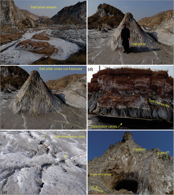
a Salt brine stream. b Salt pillar. c Salt pillar with cross-cut relationship of fractures indicates tectonic deformation in the region. d Salt pinnacles and cave development in salt bed. e Dissolution pots in salt bedrock. f Evaporite outcrop with alternate beds of gypsum, shale, and sand.
Faulting plays an essential role in exposing the evaporites in the Karak region. Due to tectonic forces and the malleable nature of evaporites, the Karak region exhibits distinctive salt domes with faulted and folded anticlinal salt ridges. The appearance of sinkholes in this region differs from that of other salt basins, e.g., Texas and Read Sea, because the best exposure of thick evaporite units on the surface results from fault structures and erosional features. The rocks in the Karak region are highly saturated, weathered, friable, and deformed, with extensive geological discontinuities (Fig. 7). These discontinuities exist in the form of closely spaced joints and fractures in the Siwalik rocks and recent sediments (conglomerates, sands, and siltstone) that provide pathways for water movement downward or laterally to the bedrock, dissolving salt and creating brine. These unique dissolution features of the Karak region probably lead to the most rapid development of sinkholes worldwide in the karstification process.
These sinkholes uncover an essential characteristic of the evaporite karst topography. The considerable surface exposure of Karak evaporites combined with underground water and tectonic stresses make this region vulnerable to developing karst landforms fostered by geohazards. As a result, various environmental issues caused by sinkholes pose a significant risk to humans and property in this region. During the field visits, we observed cover collapse, bedrock collapse, and bedrock sagging sinkholes in four villages with considerable damages (Fig. 5). The ongoing development of sinkholes in this less-developed region substantially impacted the local community, including damage to local infrastructure, farmland, and communication networks. Therefore, the mapping of surface subsidence underscores the sinkhole detection and associated damages in the populated region. Note that the resolution of InSAR-derived velocity is 90-by-90 meters, which may be too coarse to capture very small sinkholes. However, our field investigations show that typical sinkholes often produce surface subsidence distributed in a much larger area than the final collapsed part, making the InSAR result a good indicator for local authorities to conduct field monitoring. The revealed high subsidence rates emphasize the critical need for incorporating various approaches into urban planning systems to effectively mitigate and manage sinkhole issues in this vulnerable region where the settled population is still residing.
To conclude, this study investigates sinkholes in the Karak region using nine years of InSAR data. We identify severe ground subsidence (up to 29 mm/year) widely distributed. Resistivity cross sections, in combination with water table data, mark the shallow subsurface layers and groundwater. Based on the deformation pattern, groundwater distribution, and lithological information, we catalog sinkholes into cover, bedrock collapse, and bedrock sagging sinkholes. We find that the former two catalogs are mainly distributed along the fault zones due to surface exposure of evaporites. Bedrock sagging sinkholes are more common in basin regions where evaporites are in the subsurface covered by quaternary alluvial deposits. Sinkhole subsidence is mainly controlled by water percolation along fractures in quaternary sediments that interact with salt, causing karstification. It is very challenging to control the karstification processes that trigger sinkholes, but effective planning and technical innovations in resistance to subsidence are essential for hazard mitigation.
Methods
InSAR data processing
To assess sinkhole-induced subsidence, we process the Sentinel-1 SAR data from the European Space Agency (ESA), spanning 9 years (2015-2023). The semi-arid settings of the Karak region present a favorable environment for employing the InSAR technique. A total of 204 and 215 SAR images are processed for ascending track (AT-173) and descending track (DT-5), respectively, from January 2015 to October 2023. The acquired data are ingested into the Sentinel-1 processor69. The maximum temporal baseline is set to 37 days to construct 515 ascending and 558 descending interferograms (Figure S1). The interferograms are multi-looked with a factor of 23 × 6 in azimuth and range, resulting in a ground resolution of 90-by-90 m. Shuttle Radar Topography Mission Digital Elevation Model (SRTM DEM 30 m) is used for coregistration, reference-phase removal, and geocoding. We apply the Statistical-cost Network-Flow Algorithm for Phase Unwrapping (SNAPHU) to unwrap these interferograms70, adopting the network programming approach71 to ensure reliable and globally consistent solutions. This approach considers phase unwrapping as a minimum-cost flow problem in which phase residues, known as positive and negative charges, equalize through network flow optimization, reducing the influence of noise.
We conduct the small-baseline subset analysis (SBAS) (Figure S2), using the LiCSBAS software, a freely available Python package for deriving the velocity and time series analysis72. Given the high coherence in this region (Figure S5), we only mask out pixels with coherence values smaller than 0.1, namely completely decorrelated pixels, to ensure we can preserve as many pixels as possible for detecting small sinkholes. The following quality check and loop-closure-phase difference are used to identify and eliminate unreliable components72. Interferograms are employed for time-series inversion following unwrapping error identification.
Tropospheric delays in InSAR may affect the deformation with similar spatial wavelength, e.g., interseismic motion and large-scale subsidence. However, in this work, we focus on the very localized subsidence caused by sinkholes distributed in flat areas with temporally linear deformation. Therefore, the tropospheric delays can be mainly reduced by the temporal-and-spatial filter implemented in the LICSBAS package, which minimizes tropospheric noises by flattening spatial and short-term temporal variations by assuming a smooth deformation trend72. The very low standard deviations calculated by bootstrap-sampled velocities over 100 times indicate that the tropospheric delays have largely been mitigated by this filtering procedure (Figure S6). This can also be roughly validated by the consistent LOS velocity maps from ascending and descending tracks (Fig. 3), from which we decompose line-of-sight (LOS) velocities into east-west and vertical components by assuming that the north-south component is negligible73.
Electrical resistivity data
To investigate the subsurface structure, we acquired vertical electrical sounding (VES) along three profiles in the Bahadarkhel (Fig. 4b), Nari Panos, and Tarkha Koyi regions (Figure S3) in October 2023. Note that the seasonal variations in groundwater levels could influence resistivity results, particularly in the monsoon-recharged aquifers of semi-arid regions such as the Southern Kohat Basin. We thus conducted the survey specifically in the post-monsoon period, though the pre-monsoon season is better for the survey given the dry surface condition. This is because the high groundwater levels recharged by the monsoon allow for observing spatial variations of the aquifer and pattern of lithological strata at shallow depth, which directly link to the formation of sinkholes.
We used the Schlumberger array with half current electrode spacing, i.e., AB/2 ranges from 5 to 150 meters, and MN ranges from 1 to 40 m depending on the current penetration and depth. The Schlumberger electrode configuration was chosen based on its capability to achieve maximum depth per unit current electrode spacing and the high vertical resolution, resulting in comprehensive subsurface information51. The VES profiles are generally oriented in the NW to SE direction, mainly perpendicular to the drainage pattern for observing the lateral subsurface lithological variations (Fig. 4b). The electrical resistivity data efficiently reveals shallow surface layers and hydrogeological properties51,53. We obtained the true resistivities, depths, and thicknesses of VES during the processing and later correlated them with apparent resistivity pseudo sections. We also collect the water table data from the Public Health Engineering department to examine the depth of water table zones in the subsurface.
Responses