Silk-inspired in situ web spinning for situated robots
Introduction
Physically intelligent embodiments can improve robots’ safe and agile operation in dynamic environments1,2,3. Unlike animals, plants, and fungi, which efficiently negotiate unstructured environments, robots are still in need of effective mobility solutions at high degrees of freedom. High-priority target application areas include natural environments, such as ecosystem monitoring, and derived anthropogenic environments, such as searching for survivors under debris. In both cases, simply deploying sensors into and through difficult-to-reach environments is urgently desired but not yet feasible for current robotic systems. We suggest that expanding the concept of embodiment is key. While soft robotics generally discusses articulated but continuous and finite-boundary bodies, we envision temporally and spatially developing, discontinuous robotic embodiments inspired by spiders’ use of silk webs. Web-spinning spiders inspire situated behaviour of robot design4, including overall architecture (from protein sequences5,6,7 to the web pattern8 of silk), functional material engagement (e.g., water-responsiveness of silk9,10,11), and material deposition strategies (silk spinning12). Silk spun into a web enables situated behaviour via local body-environment interactions in dynamic13 environments and could be considered a spider’s sensorimotoric organ of vast spatial and temporal variation rather than an external structure14. In situ web shaping thus helps spiders maintain their spatiotemporal integrity within their habitats. Inspired by spiders’ silk crafting, robots can develop non-predictable environment-determined morphologies15 during and as a part of their operation, increasing their abilities in dynamic working environments. Ad hoc approach to embodiment contrasts with traditional assembly-oriented manufacturing, which, by default, separates initial fabrication in the factory from subsequent operation in the environment.
Spiders deposit silk fibres to create web surfaces between support structures in and based on16 their environment. How the web forms a surface only partially depends on the geometry of these supports: we observed that, regardless of support complexity, the spider webs can be approximated to a single two-dimensional surface, hence morphologically simpler than its environment, that may be composed of an arbitrary number of complex-morphology elements. Web surfaces also form in nature from cast-off airborne kiting silk, i.e., lightweight silk released by some spiders for wind dispersal and discarded for/during landing. Assuming each spider deploys and later discards a single fibre per travel and the flight trajectories do not massively intersect, the individually dispersed silk fibres also reach the supports and deposit onto them one at a time. Figure 1a and Supplementary Movie 1 illustrate the stochastic aerodynamics-driven entanglement of cast-off spider kiting silk with natural plant structures varying from dry to wet, stiff to compliant, and monolithic to stratified. Indeed, also cast-off kiting silk fibres assemble into web surfaces morphologically simpler than their supports rather than random agglomerates. Although orb web development is controlled by spiders according to the environment and the kiting silk surfaces form beyond the spider’s control, the similarity in surface development hints at more universal, emergent physical intelligence associated with fibre-by-fibre deposition. As both orb webs and observed kiting silk surfaces could be used as pathways by robots more easily than the original environment without the fibres, we suggest web surfaces could also be created artificially fibre-by-fibre, and surfacing loosely dependent on environment/support geometry may have attractive use case in robot microenvironment modification and embodiment development.
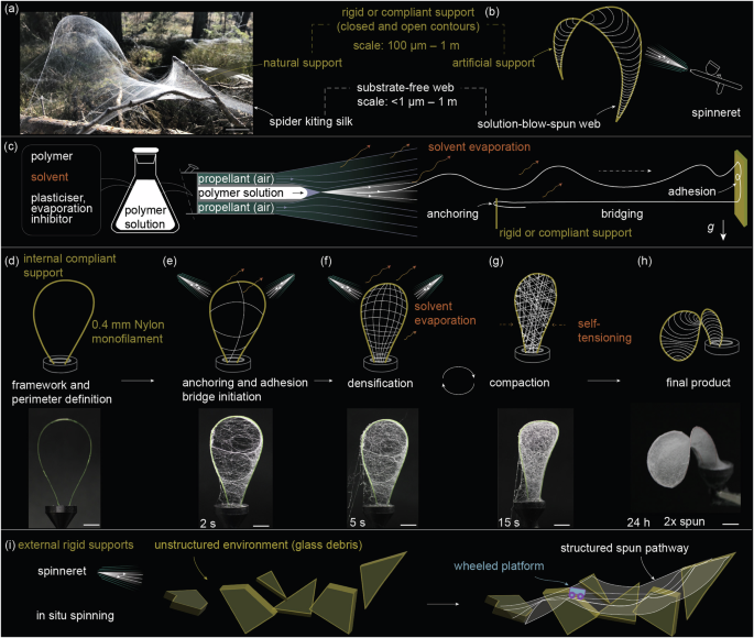
Substrate-free webs deposited from airborne a natural spider kiting silk and b artificial solution-blow-spun fibres, highlighting the conformability to non-uniform natural and artificial supports, respectively. c Schematic of solution blow spinning plasticized polymeric fibres, detailing their interaction with supports. Schematic and transient snapshot photographs of web morphological development upon spinning d a compliant single loop of Nylon monofilament, showing subsequent e bridging, f densification, and g compaction by inhibited solvent evaporation, finally reaching h a saddle-shaped web. i Transient spun pathways for crossing complex environments. Scale bars: (a) – 100 mm (d,e,f,g,h) – 10 mm.
Here, we demonstrate the rapid situated spinning of fibrous architectures, forming unsupported sections between arbitrary 3D supports (Fig. 1b). Solution blow spinning17,18,19 (SBS) is chosen to produce fibres from a liquid precursor and propel them toward supports, continuously forming webs. Unlike SBS webs produced as planar mats for scaffolding and filtration media20,21, 3D webs developed in situ substantially extend the range of spinning applications. SBS does not require an electric field22 and is thus shown compatible with complex 3D non-conductive substrates23,24 including living tissues25 using accessible (low cost and universally available) apparatus26. Only a few prior publications have demonstrated substrate-free SBS bridges between anchor points, focusing on biomaterial scaffolding for tissue engineering23,24,25. Little attention has been paid to specific interactions between the SBS-deposited fibre and the substrate, morphological development of free-standing non-supported 3D surfaces formed from airborne fibres, and robotics use cases of in-situ spinning in general27,28. In-flight fibre printing29 promises precise in-plane control and bridging substrate-free fibres with a relatively high (>100) aspect ratio; however, spider-like spinning micrometre-scale fibres across three-dimensional and compliant metre-scale substrates remain a challenge. Rather than individually placing each web anchor point in its final position, as is customary in coordinate-based manufacturing and in spider orb webs, we engage multiphysics rules—including aerodynamics, solvent diffusion kinetics, viscoelasticity, volumetric shrinkage, and structural mechanics—to develop the webs. This rule-based deposition contrasts with a centralised controller or user determining each fibre’s placement based on visual or haptic sensory feedback. Our strategy places fibres primarily based on aerodynamic interactions between the blowing agent and the ad hoc supports, including fibres deposited previously, at a rate beyond coordinate-based approaches. Unlike spiders that alternate and combine specialised spinnerets for different web types30, we show a single contained solution and spinneret to produce webs structurally diversified by support type.
Although flow- and confinement-induced phase transition from concentrated aqueous protein solutions, as in spiders31,32, promises ultimate in-situ capability, the artificial spinning of natural spider and silkworm silk33,34,35 currently relies on natural feedstock and suffers from low scalability, motivating artificial silk development36. Spinning of other potentially applicable biopolymers lies outside the present scope. We focus on post-spinning tensioning9 as the enabler to situated webs.
We focus on expressions of embodied intelligence as direct mechanical feedback received by individual fibres from the environment during attachment, closing a short control loop and enabling environment-situated operation. We conceptualise temporal web spinning to define robotic embodiments and their microenvironments using case studies of ad hoc internal (within the robot’s embodiment) and external (at the boundary or external to the embodiment) structuring. In the internal structuring case study, a conventional pneumatic gripper is developed by spinning working surfaces in situ, suggesting perspective in rapid reconfiguration and remodelling task-specific grippers on-demand, as opposed to using factory-made universally applicable soft grippers. As an example of external structuring, we show in-situ spun temporal ‘highways’ that make natural and anthropogenic continuous environments passable for wheeled mobile platforms requiring structured routes, illustrating the potential in sensor deployment for search and rescue missions.
Results
The concept for in-situ spinning
In SBS, a jet of gaseous propellant extrudes a polymer solution, continuously forming airborne fibres through shear forces and increasing viscosity due to concurrent solvent evaporation. For spinning, we modified a commercial airbrush with a heating coil, as illustrated in Supplementary Fig. 1. A reduced viscosity of heated dope facilitated spinning. A gradual increase in viscosity during spinning complemented solvent evaporation for fibre solidification. When incompletely solidified airborne fibres encounter solid 3D objects, including previously spun webs, they display a rich spectrum of adhesion, anchoring, and bridging behaviours (Fig. 1c). In the prototypical experiment, we demonstrate spinning on compliant supports consisting of single and quadrupole loops of Nylon monofilaments in Fig. 1d and Supplementary Movie 1, respectively. During SBS, airborne fibres became entangled with the compliant filament, effectively anchoring onto it (see Fig. 1e)—a brief exposure initiated fibrous connections spanning several centimetres, bridging gaps between separate support sections. Bridging confirms fibre continuity across disparate support sections as fibres develop multiple entanglements along their lengths. Continued SBS after bridging led to fibre densification (Fig. 1f) to form a web. The web initially mirrored the geometry defined by fibre bridges (Fig. 1e); however, as the solvent was not completely evaporated during flight, the deposited fibres shrunk in length and self-tensioned the web, constituting the compaction phase (Fig. 1g). The propellant flow also elastically deformed the compliant supports; the fibre bridges fixed the deformed shape, storing elastic energy. Self-tensioning developed a cohesive force that interacted with and amplified the deformation of the compliant boundary, effectively minimising the web area and tautening the web. Self-tensioning continued after the termination of propellant flow. As a result, SBS fixed an elastic support that outlines the overall 3D structure to a contour very different from the initial (Fig. 1h, as compared to Fig. 1d).
Supplementary Fig. 2 further illustrates the diversity of web-tensioned structures for increasing substrate loop count. Multiple geometries are possible for each support arrangement, with bridging defining a particular configuration. Rather than being selected from a finite set, the web configuration is guided as a developmental process towards specific configurations through centralised input. In our experiments, the human operator controlled the spinneret by hand using visual feedback, but future implementations could employ central processors with machine vision to control the spinneret. In both scenarios—whether human-operated or automated—the centralised control provides only a global strategy. The distributed, local, fiber-by-fiber development of the morphologically complex web, which is the focus of this paper, is fully delegated to the embodiment in both cases, offloading this process from the brain or other centralised controllers.
Spinning on supports contextually internal to the robot’s body, as in Fig. 1d–h, manifests rapid on-demand fabrication. Integrating high aspect ratio supports with non-planar surfaces for robot embodiments has been challenging. However, SBS formed a 10-cm-scale high-aspect-ratio 3D fibrous structure with a substrate-free bridging surface in Fig. 1g in merely fifteen seconds—comparable to film processes such as dip-coating and substantially faster than popular rapid fabrication technologies such as fused-deposition 3D printing. On-demand embodiment creation blurs the agent’s physical boundaries, allowing agents to spin webs on external objects to establish temporal bodily extensions, as shown in Fig. 1i, functional for mobility across challenging courses.
Emergent, gradual shaping of substrate-free webs
Shearing of the polymer solution exiting the spinneret causes partially solidified fibres to align with the propellant flow direction and be carried, suspended in the propellant, towards potential supports. Here, we attempt to classify the morphological space of structures formed when aligned, suspended fibres encounter supports. A rich morphological space already emerges when spinning on non-compliant supports of the simplest geometry. Figure 2a outlines the parametric space of webs spun towards the circular aperture of diameter D in a planar electrically isolating rigid poly(methyl methacrylate) (PMMA) support; a second parallel planar PMMA support, without cut-outs, was positioned at a distance WD of 200 mm. We observed distinct geometries from planar to tunnel-like by varying only D and the spinning angle αs, exemplified in Supplementary Figures 3a–c. Fibres favourably deposited at a low incidence angle, yet the jet instability of the propelled fibres bridged up to 220 mm in-plane (at αs = 10°, D = 200 mm) and 200 mm cross-plane (at αs = 90°, D = 60 mm) distances corresponding to taut planar (Fig. 2b) and tunnel-like (Fig. 2d) sections, respectively. When the propellant flow encountered a wall behind the aperture, it diverged, creating tunnel-like morphologies. Figure 2d and Supplementary Movie 2 demonstrate the spinning process and confirm the tautness of the planar substrate-free web: when applied to the centre, it carried a 0.7 g load. The web was also significant by substrate-free area: we achieved 0.038 m2 taut planar surfaces and approximately 0.03 m2 tubular sections.
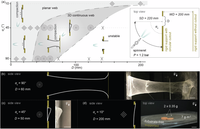
a The morphological space of webs for variable support opening diameter D and spinning angle αs. b–d Characteristic profiles (left) and corresponding photographs (right) of αs-keyed web morphology development, transitioning from b tunnel-like at αs = 90° to c intermediary 3D at αs = 45° and d Planar shape at αs = 10°, tautened by self-compaction. In photograph of (d), a payload is applied to the centre of a planar web section to demonstrate web tautness. The label g, accompanied by an arrow, shows the direction of gravity. Scale bars: (b–d) – 20 mm.
The formation of the planar and 3D webs, illustrated in Supplementary Movies 1, 2, involved the temporary collapse of substantial surface sections. Prolonged spinning fully repaired the ruptures, resulting in and later evidenced by denser fibre bundles. The stochastic agglomeration of partially solidified fibres also contributes to fibre bundling, resulting in a hierarchical web structure.
Small-diameter (D ≤ 20 mm) apertures were fully sealed even at αs = 90° (propellant pressure: 1.2 bar), forming a uniform continuous planar web on the front surface, without a measurable difference in fibre density between the aperture and supported areas. This evidence of jet instability (whipping) at an increasing spinning distance SD readily produces the desired randomization of airborne fibre pathways for entanglement with any support it may encounter in flight. Unexpectedly, the thin SBS web was exposed to a vigorous propellant stream at αs = 90°, and the resulting nonwoven was fully taut, with no sagging observed, evidencing fibre compaction due to solvents evaporating post-spinning. An increasing aperture size (D = 30–40 mm) resulted in a three-dimensional surface extending towards the interior of the chamber, with the aspect ratio rapidly increasing with increasing D, reaching a tunnel/funnel shape at D = 40 mm. This suggests the fibre jet was spread on an approximately 40 mm diameter target, with the fibre incidence probability decreasing outwards. When the spray cone cross-section approached the aperture diameter, the fibres occasionally entangled with the edges, whereas most fibres passed the aperture and formed a continuous out-of-plane web. D = 50 mm yielded a continuous and uniform tunnel-like structure encompassing the whole 20 cm WD, evidencing efficient bridging and entanglement of the successively spun fibres on the previously spun web. At a fourfold length-to-entry-diameter ratio, the tunnel’s internal diameter was reasonably uniform; however, the tunnel distal diameter reduced to approximately 50% of D due to self-tensioning. An even larger D = 70 mm did not bridge into a defined web. αs-keying is effective for vast morphological variation: at low αs, the void bridged parallel to the support plane, whereas the tunnel walls were perpendicular to the support plane: flow-aligned airborne fibres bridged up to 220 mm in-plane (at αs = 10°) and 200 mm cross-plane (at αs = 90°) gaps. This evidences bridging and densification favourably occurring at a low incidence angle (i.e., low αs) to the propellant stream. Bridging 200 mm D at the same WD value (at αs = 10°) evidences the presence of individual fibres comparable to WD in the propellant flow and at least temporal fibre continuity from the nozzle to the substrate.
We observed more than a single surface formation in some D and αs combinations, particularly at the transition zones between distinct morphologies (e.g., D = 50 mm; αs = 45° in Supplementary Fig. 3b). A gradual change in the eventual surface morphology was observed even at the largest free-standing planar area (D = 200 mm and αs = 10° in Supplementary Fig. 3a), where the web covered the front and back sides of the aperture plate at the proximal and distal edges (from the spinneret), respectively. Plane transition evidences the previously spun material affecting local aerodynamic forces. Although multiplane formation is associated with suboptimal material use in simple geometries (e.g., at a single aperture), it is essential in increasing the structuring level, as multiple generations of temporary structures eventually converge to a single surface.
Web line anchorage and adhesion
Attachment is fundamental in spiders’ orb webs, with each anchor grafted to its specific microenvironment. More broadly, as spinning allows for the gradual development of spun pathways and robotic embodiments, prolonged or repeated spinning can increase the robot’s bodily capabilities, drawing parallels to the intertwined process of growth and physical training in organisms. For both cases—attachment to the environment and integration with the robot’s body, often intertwined—we need to explore how new fibres attach to previously existing structures to form an integral web and body.
Airborne fibres interact with encountered high-aspect-ratio supports by combining physical adhesion and entanglement. Figure 3a micrograph evidences the winding of first-encounter fibres around a Nylon filament support, embedding it within a fibrous semicontinuous mesh by fibre densification. A close-up micrograph of embedded support is given in Fig. 3b and a cross-sectional view in Fig. 3c. A prolonged spinning from a constant direction densified the web without further promoting anchoring; however, in our experiments, rip failure always occurred outside the anchor area (Supplementary Movie 3), evidencing the anchoring strength was limited by the web’s tensile strength rather than adhesion. Fibre-level wrapping of a closed-loop filament across its whole perimeter recalls silk use practices of spiders and insects in prey immobilisation and cocoon building.
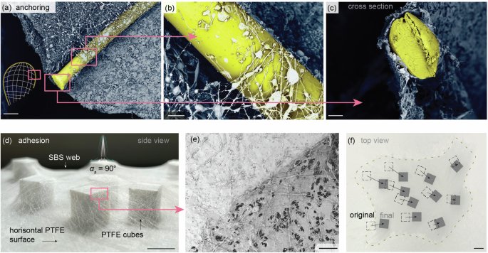
a Web anchoring to a high-aspect-ratio compliant support–a Nylon monofilament. b, c Close-up images of web anchoring. d Interconnection of scattered PTFE cubes by in situ web spinning. e Support-dependent web morphology illustrated by the interface between supported and substrate-free sections. f Post-spinning convergence of the web-covered cubes, demonstrating web adhesion on PTFE and self-tensioning. Scale bars: (a,e) – 0.5 mm; (b,c) – 100 µm; (d, f) – 5 mm.
We demonstrated spin-augmented anchoring on a flat, horizontal PTFE substrate randomly populated with loose objects of low aspect ratio, specifically PTFE cubes. Spinning developed a single, continuous, non-planar nodal web encompassing all cubes with cemented morphology at top faces, illustrated in Fig. 3d. In Fig. 3e, the interface between the free-standing and support-covering web sections showed a sharp transition from a nodal network to a cemented morphology, respectively. This illustrates the achievable several deposition modes when spinning with an identical precursor solution at identical process parameters, material, and distance. The nodal network (Fig. 3e, bottom-right) evidences inhibition of solvent evaporation: the deposited material is allowed to reflow to interlock the threads. Fibre interlocking is necessary for most considered applications, contributing to load capacity and web integrity. Adhesive interconnections recall the promotion of web integrity by sericin glue interconnections in silkworm cocoons37. Adhesive interconnects are also achieved by applying a small amount of adhesive to prevent the unravelling of engineered nonwovens. In our study, unlike previous engineered solutions and even natural spider webs, reflow achieved fibre interconnects using a single material and spinning step, simplifying fabrication.
A single-stage spinning converged the PTFE cubes by approximately 16% by self-tensioning, as shown in Fig. 3f, evidencing fibre anchoring on the PTFE cubes’ top faces and edges. Spinning merged individual cubes into a single assembly, hinting at potential future developments in embedding functional agents into the web microenvironment.
On granular substrates, fibre post-tensioning could initiate various emergent behaviours. The dope settling into interparticle spaces could enhance the hold on individual particles, establishing better anchorage. The fibrous bridges transform the initially granular environment into a coordinated structure. The granular particles, held together by tensioned fibres, express friction between contacting rough particle surfaces; this mechanical interlocking recalls granular jamming, which is a transition from a fluid-like to a solid-like state.
We tested various support materials for attachment, including adhesion and anchoring. In addition to material engaged in demonstration experiments throughout this paper—polytetrafluoroethylene (PTFE) blocks, Nylon filaments, mineral glass shards, organic glass (PMMA) plates, printed PLA posts, and moistened natural reed—we also tested additional materials typically challenging for adhesion: small-pore polyolefin foam blocks soaked in water, large-pore polyurethane foam blocks soaked in mineral oil, closed-cell polyethylene foam blocks, closed-cell polystyrene foam blocks, silicone sheets, and waxy natural plant leaves, as shown in Supplementary Fig. 4. The spun webs successfully attached to all materials and physical appearances (fibres, foams, sheets, natural plant surfaces) listed.
Adhesion on most tested support materials—such as Nylon, glass, PMMA, and PLA—was irreversible: the web ripped at the substrate-free section before peeling off (i.e., delaminating from) the anchor. The SBS web even anchored on challenging low-surface-energy materials, particularly PTFE. We characterised PTFE for SBS adhesion strength. T-peel test from a planar PTFE support yielded 12.6 ± 1.6 N m−1 adhesion strength (Supplementary Fig. 5). However, as shown in Supplementary Fig. 4, adhesion and anchoring are difficult to defactor from each other in typical experiments, as the fibre length and reach always caused concurrent anchoring.
Efficient attachment to multiphase systems, such as solid foams saturated with various liquids, was particularly notable. Upon loading, the webs ripped from unsupported sections between soaked foams but did not delaminate from the foam surface. However, the fibre bridges between liquid-soaked supports showed moderately lower mechanical strength, possibly due to the exchange and mixing of two mobile liquids: the liquid in the external foam pores and the plasticiser in the internal pores of the web.
Morphology of substrate-free webs
The cut edge of the free-standing section in Fig. 4a illustrates the nodal web. Upon encountering planar support, the decelerated air convection and solvent evaporation rates almost entirely connected the nodes (Fig. 3e, top-left), allowing for the highest possible contact area and strongest adhesion. Local post-tensioning, resulting from fibre shrinkage after contact, could promote mechanical interlocking by pulling the material into microscopic textures, pores, or irregularities of rough substrates. This effect is significant on rough supports, as observed on, e.g., natural reed surfaces below. Local post-tensioning could further enhance the adhesion strength. Similar multi-stage anchoring on smooth surfaces (such as glass) involving a dedicated cementation layer has also been described for weaver spiders38. Spinning fibres with residual solvent content enhanced physical adhesion: the not fully cured droplets acted as cementation layers for the previously deposited fibres. Although the surface-adhered web has lost most of its fibrous characteristics (Fig. 3e, top-left), reminiscent fibres are observed, confirming limited flow rearrangement.
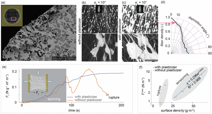
a A cut section of the substrate-free web. Morphology of b unplasticized and c unplasticized substrate-free webs spun at αs = 10°. d Deposition angle of plasticized fibres spun at αs = 10°. e Characteristic transient self-tensioning behaviour of plasticized and non-plasticized webs spun onto a rigid, sensorised support. f Surface density dependence of self-tensioning and rupture forces per width for plasticised and unplasticised webs, respectively. Scale bars: (a) – 5 mm; (b,c) – 100 µm.
Fibre reflow was promoted by including 1-ethyl-3-methylimidazolium trifluoromethanesulfonate (EMIM-Otf) organic salt as an evaporation inhibitor into the spinning dope. During the flight, evaporation from the solvent-rich dope solution was uninhibited, allowing fibre formation. Fibre formation was further accelerated as the dope cooled by approximately 38 °C from the heated spinneret to room temperature web. Upon attachment, the remaining solvent content interacted with the evaporation inhibitor, promoting reflow. The relatively hydrophobic ends of EMIM+ and Otf– ions associate with the hydrophobic polymeric backbone of the PVdF-HFP polymer, ‘trapping’ solvents. EMIM-Otf content is to broaden the temporal window of viscous reconfiguration of the deposited material at the final spinning stage. The critical transition from flow to reflow is primarily governed by the inhibitor concentration rather than the initial solvent quantity in the dope. More extensive post-spinning morphological rearrangement improves cementation, yet the ion-mediated bonds between adjacent polymer chains at a decreasing solvent content contain the reflow. After complete evaporation of the volatile solvent, EMIM-Otf with negligible vapour pressure was retained in the web as an ionic liquid plasticizer.
The nodal morphology of the substrate-free web (Fig. 3e, bottom-right) is detailed in Fig. 4b, c for non-inhibited and inhibited solvent evaporation, respectively. The reflow promotor inclusion changed the bead-on-a-string structure (Fig. 4b) into a nodal network (Fig. 4c). The thin fibrous links with diameters starting from 200 nm provide flexibility in-between nodes of 10 μm characteristic size, recalling a scaled-up version of spider silk protein39.
Spinning even at a close-to-minimal αs of 10° (Fig. 4c) resulted in a uniform web of broad fibre angular distribution. Although stretching of fibres along the propellant flow expectedly resulted in the largest share of fibres aligned with the spinning direction, the randomization of fibre orientation in the propellant flow caused the fibre deposition angle to vary broadly: 49 ± 18% share of fibres deposited perpendicular, at 90° to the spinning direction (Fig. 4d).
The plasticizer and reflow promotor made self-tensioning accessible. In situ tensiometry of a web spun between parallel PLA (excellent physical adhesion confirmed above) posts (typical course of tensile force Ft is shown in Fig. 4e) showed similar self-tensioning for the unplasticized and plasticized webs during spinning. After the completion of spinning, the non-plasticized web ripped, as evidenced by a random, multi-peaked Ft profile. The peak force reached Ftmax = 23 N m−1 m2 g−1, normalised for web width and area density. With EMIM-Otf plasticizer content, the web spun on rigid supports accumulated and retained tension, reaching a peak Ftmax of 19 N m−1 m2 g−1 approximately one minute after the completion of spinning (Fig. 4e) without visible ripping. In our forced air flow drying setup, some parts of the web may have been exposed to airflow more efficiently than others; however, the possible effects from uneven solvent escape were likely diminished in a few minutes. The negligible vapour pressure of the EMIM-Otf plasticizer resulted in a taut web after solvent evaporation. A higher surface density web promoted exponentially higher Ftmax for surface densities up to 66 g m−2, as in Fig. 4f; however, the tensile strength was proportional to the surface density, as shown in Supplementary Fig. 6. Thus, for higher surface densities, the course of tensioning shifted toward the post-spinning phase. Supplementary Movie 3 shows a thicker, 155 g m−2 web increased Ft 36 times in nine minutes from the completion of spinning.
SBS as a step in building robot bodies
Using an in situ spun template, we demonstrated rapid ad-hoc spinning of a two-fingered pneumatic gripper for delicate handling of fragile objects. The gripper was developed step-by-step on a printed pneumatic connector base. First, two loops of Nylon fishing line, one for each finger, were attached to the connector (Fig. 5a). Next, a web was blow-spun in a single run (propellant pressure: 1.0 bar), forming a continuous enclosed web with the final shape developed by self-tensioning (Fig. 5b). Multiple stacked surfaces were observed in some areas, especially at the connector-support interface, yet the outermost surface, defining the gripper’s boundary, developed most uniformly. Finally, the gripper was completed by spray-coating the entire structure with silicone elastomer, filling voids in the web by surface tension (Fig. 5c). Pinhole defects were further repaired by partial dip-coating. Although both web and silicone precursors were liquid solutions, silicone spraying did not produce fibres; instead, the aerosol was deposited on the spun web surface to coat and impregnate it. The internal cavity remained hollow. After curing the silicone, the pneumatic effector, already connected to a compressed air source, was ready for pressurisation and operation. The spun web is to define the location of the elastomeric membrane during gripper formation. The finished gripper, consisting of a single internal hollow cavity, operates on the principles of conventional pneumatic deformable-boundary grippers: the fingers opened at positive and closed at negative pressure applied externally, whereas the web only contributed slightly as a silicone reinforcement. The compliant Nylon supports, which initially supported the web during spinning, remained within the structure as strain-limiting elements, guiding and constraining the deformation to enhance control, contributing to lift capacity, and retaining the shape.
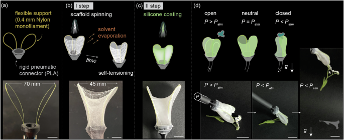
a The definition of gripper finger outlines by a loop of Nylon for each. b Spinning a web directly on the Nylon loops acting as the primary reinforcement. c A silicone elastomer coating is applied to the web as the secondary reinforcement. d Pressurization of the resulting hollow conformable chamber through an inbuilt pneumatic connector, showcased by the delicate picking of a small flower. Scale bars: (a,b,c) – 10 mm; (d) – 20 mm.
The gripper was demonstrated in gentle pick-and-place handling of a delicate object – a small flower (Fig. 5d and Supplementary Movie 4). While the Nylon loops defined the core closing kinematics, the web-reinforced silicone layer contributed to compliant interaction with objects, allowing the formation of interweb ‘pouches’ that could securely hold items. Due to naturally adhesive properties, the silicone contacting surface potentially contributed to grasp strength, although the flower specimen was light. Contact area to the specimen was achieved via a compliant and thin (approximately 30 μm) silicone membrane, and support strength was further increased by the embedded Nylon filament.
In situ spinning allowed for the fabrication of a functional gripper, shown in Fig. 5, in a short time (limited by the curing time of silicone, 30 min, in our experiment) using a minimal-investment setup (an airbrush as the spinneret) and a minimal amount of materials (approximately 0.5 g of Nylon, SBS web, and silicone). In contrast to the more traditional approach of attaching a fluid source to the effector as the final step, the SBS gripper was constructed step-by-step on top of a pneumatic connector. The strategy supports a high level of repair and customization: In follow-up developments, additional layers could be spun to adjust the configuration, or the whole gripper could be rapidly redeveloped on the existing fluidic connector base for a new gripping task without even detachment from the compressed air source. A pneumatic gripper of comparable complexity and tunability would need considerably more steps or time to complete by moulding. Single-step elastomer direct printing would contest simplicity and tunability, yet not the time margin from idea to deployment, and it would be more challenging to 3D-print the demonstrated high-aspect-ratio articular membrane.
Temporal microenvironment structuring
Embodiment-enabled mobility, achieved by temporal spinning that balances body augmentation and environmental modification, is demonstrated in simulated exploratory deployment scenarios across complex 3D anthropogenic paths and simulated natural terrains composed of rigid and compliant elements. All case studies detailed below are illustrated in Supplementary Movie 5.
First, we consider a rescue mission in a collapsed building with only a single inlet to the uncharted internal void. In the simplest setup, the circular 70 mm diameter entry aperture was terminated by a wall at 150 mm depth (in Fig. 6a, recalling the scene in Fig. 2b above). Spinning towards the entry (propellant pressure: 1.5 bar) initiated a fibrous bridge (Fig. 6a right). The bridge’s evolution involved a nearly complete collapse (recalling tunnel collapse in Supplementary Movie 2) due to stress accumulation in a thinner section; this damage completely recovered in continued spinning. The bridge, which weighed 0.61 g, sustained a 100-g steel balance weight placed close to the entry point, shown in Fig. 6b, confirming its load-bearing capacity. The middle section sustained at least 10 g weight, as shown in Supplementary Fig. 7. The non-uniform surface density along the bridge is well-expected due to unidirectional spinning, which also impacts its load-bearing capacity.
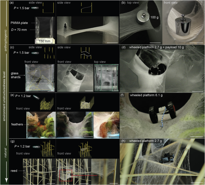
a Formation of a web bridge to an enclosed interior through a circular gateway. b Demonstration of the load-bearing capacity of the spun bridge at a 100 g load. c Spinning a pathway across an obstacle course lined with sharp glass. d A 13 g rolling chassis crossing the glass shard obstacle course. e Spinning a bridge across a pathway lined with extremely compliant impediments – feathers. f A wind-up rolling platform crossing the feather course. g Crossing a simulated reedbed by a spun bridge. h A 2.7 g platform rolling across the reedbed course. Scale bars: (b,c centre,d,e right,f,g right, h – 25 mm; (a,c left and right, e left and centre, g left and centre) – 50 mm.
Next, we simulated scattered debris using several successive layers of glass shards with irregularly shaped sharp edges; Fig. 6c, left, shows the initial scene. Spinning towards the entry point (propellant pressure: 1.5 bar) created a passage across the 200-mm obstacle course in approximately seven minutes. Aerodynamic forces acting on glass wall fragments directed the propellant stream to deposit the fibers into a continuous pathway, as shown in Fig. 6c, middle, right. The spinneret location was continuously adjusted to better comply with the evolving structure. Finally, the sharp glass edges became fully embedded in the bridge. A simple wheeled platform – a 2.7 g toy car chassis carrying a 10 g payload – successfully rolled across the bridge (Fig. 6d), illustrating how such bridges can facilitate reaching and supplying survivors in a rescue mission.
The next scene, shown in Fig. 6e, was composed of compliant natural bird feathers arranged from three sides. Spinning towards the feather-lined trajectory (propellant pressure: 1.2 bar) first caused entanglement and adhesion of the fibres to the feathers. Fibre self-tensioning subsequently compacted the web, forming a tautened pathway shown in Fig. 6e, middle. A 6.1 g wind-up toy could now easily roll over the fibrous bridge (Fig. 6f).
In the final scene, natural reed stems were arranged vertically, as in Fig. 6g, left to mimic a reedbed. Before SBS, the reed was moistened with water spray to simulate natural reedbeds near lakes, where precipitation and moisture are common. Wet reed is also a more challenging substrate for adhesion than dry reed. Airborne fibres (propellant pressure: 1.2 bar) efficiently entangled with the wet stems and leaf blades of reeds (Fig. 6g, right), embedding thinner sections into the web. The formed passage is shown in Fig. 6g, middle. The thin fibrous bridge sustained the weight of a 2.7 g toy car chassis rolling across it (Fig. 6h).
The simple wheeled platforms successfully passed all the obstacle courses under gravity stimulus; however, autonomous motorised platforms of comparable size and weight are also available. By selecting perhaps the simplest form of a rolling platform—a part of a toy car—we demonstrated that the spun bridge served as a simple structural element. We did not even need to increase traction, as the basic plastic wheels rolled well on the plasticised web; however, Velcro-like attachment approaches may be helpful in, e.g., vertical spinning in future implementations. In contrast, recalling the obstacle courses before spinning, even highly articulated soft robots would struggle to pass all of them. Instead, in situ spinning (as opposed to prefabricated) rendered all obstacle courses passable by even the simplest rolling platform.
In exploratory deployment missions, the fibrous bridges are intended for a single or a few-time use only; in our experiments, each fibre pathway was loaded approximately ten times. However, in future implementations of on-board spinneret, the robots could also repair or reconfigure webs for each passage.
We noticed that, compared to more structured environments like the planar PMMA walls in Fig. 2, the unstructured environments excelled in efficient material consumption. Unlike the excessive material accumulation on planar wall sections, as also in Fig. 6a, b, most fibres spun into our simulated unstructured environments in Fig. 6c, e, g contributed to web formation. The planar support experiments that implied material overconsumption are not representative of the intended use cases of in situ spinning and served as means of morphological space discovery, thus the simulated track experiments evidenced efficient material consumption. This aligns with spider kiting silk observation, as most high-aspect-ratio airborne fibres eventually become entangled.
Discussion
We address a core challenge in soft robotics: enhancing robots’ capabilities in high-degree-of-freedom mobility and interaction. While most robotics research tackles this task with centralised computation, leading towards environment-specific robots that face increasing control challenges, we propose a universal, bottom-up, embodiment-centric approach. In situ spinning enables the sculpture of situated robot embodiments, achieving intelligent behaviour aided and guided by the environment. In-situ sculpted components can be regarded as the robot’s transient organs, tasked with primitives such as delicate handling and complex environment negotiation, demonstrated here as a finger for manipulation and a pathway for movement, respectively.
In our demonstrations, embodied intelligence was engaged during spinning, including the post-tensioning phase that occurred several tens of seconds after fibre deposition. The fibrous bridge was developed via embodied intelligence and functioned as a simple structural element after the completion of spinning. This suggests a paradigm shift from considering embodied intelligence as confined to the operation of prefabricated (soft) structures to recognizing the gradual embodiment development process as an inherent component of embodied intelligence. The pneumatic gripper was first sculpted in situ and then engaged for a compliant pick-and-place task, showing embodied intelligence in both stages. In situ development enabled emergent behaviours, including post-spinning self-tensioning reconfiguration, self-repair, and incorporation of surrounding particulate matter—capabilities unattainable with prefabricated embodiments.
Surprisingly, the same process—in situ spinning—can transform simple supports into morphologically complex functional structures (e.g., as in gripper shaping) and simplify complex environments (e.g., for mobility). Spinning contained complex natural and anthropogenic environments, reducing their degrees of freedom from infinite to a single degree—a single surface. This allowed conventional rolling platforms, optimal for single-degree-of-freedom pathways, to pass high-degree-of-freedom obstacle courses non-destructively and without causing secondary collapses. This complements the articulation of soft, infinite-degree-of-freedom robot bodies adhering to soft animal models such as snakes. Instead of engineering highly articulated contact surfaces that still lack universality, we develop the robot to align with (the gripper) or integrate into (the pathways) the microenvironment. Using aerodynamic forces, SBS lines pathways and provides navigational cues in obstacle courses of arbitrary compliance, exfoliativity, and electrical conductivity, challenging by shape-morphing of a soft body because of the danger of piercing (with glass shards, Fig. 6d), exceeding loading density (suspended on feathers, Fig. 6f), or potential slippage on a wet vertical surface (reed stems, Fig. 6h).
Both, internal and external structuring cases accept on-demand remodelling by, e.g., feeding filament to define a new finger outline or respinning the collected web, as spiders, in future developments. In gripper development, a minimal-configuration primary (flexible) reinforcement is first deployed, followed by in situ spinning on it to form complex-morphology webs that act as secondary reinforcement for additional structures, such as films, guided and supported by both levels of reinforcements. Such nested support strategy enables rapid fabrication of, e.g., elastomeric structures with high-aspect-ratio unsupported sections with shapes dictated merely by the perimeter of the primary reinforcement. We foresee new avenues for compliant support design for subsequent stochastic in-situ spinning of physically intelligent agents and their components—a shift in robot design and fabrication.
Gradual solidification reflows the fibres deposited on internal and external supports into a nodular, self-tensioned web with environment-defined morphology and adhesion, enacting situational programming like in spider orb webs. In-situ spun web adhered even onto challenging support materials such as PTFE or wet reed. This implies our solution is capable of adhering to virtually any object in a complex, chaotic environment, providing maximum success in pathway creation. Timed post-tensioning shaped the collective entity of the web in conjunction with external or internal supports, advancing 4D printing by including the environment.
Low material consumption (surface density starting from 7 g m−2) and efficient material use in unstructured environments allow for a consumable allocation, supported by biological examples like the kiting silk of spiders (as in Fig. 1a) and the mucus trails of snails. In situ body sculpture also suggests imminent clinical applications such as the in-situ spinning of colonic stents (similar scale as the tubular structure shown in Supplementary Movie 4), organ supports (confirmed by the load-carrying capacity of the bridge in Fig. 6c), scaffolds for structural repairs, and access pathways for minimally invasive interventions.
The system’s dual capacity of adding complexity to simplicity and simplicity to complexity further highlights the emergence of physical intelligence expressed beyond the agent’s central control, fundamentally impacting robot fabrication strategies. In situ spinning transitions from model-based methods, such as stereolithography and computer-numerically-controlled machining, to rule-based approaches that leverage multiphysics (e.g., aerodynamics) principles and ad-hoc templates to shape robots’ embodiments.
In situ spinning suggests scalability advantages. Although similar apparatus can be used for spinning and spraying, as in this work for web formation and subsequent elastomer coating, they are fundamentally different processes regarding morphological development. Spraying produces zero-dimensional aerosol droplets, whereas spinning shears the dope solution into one-dimensional fibres that span the working space to assemble into two- and three-dimensional structures. Stochastic anchoring and deposition of undulating individual fibres involving sequential bridging, densification, and compaction stages, including partial collapses, promotes a hierarchical and spatiotemporally scalable morphology reminiscent of the supportive and integrative venation in vascular organisms.
The demonstrated low gravimetric density of 7 g m−2 would be challenging to manipulate as a sheet and stored in rolls, suggesting in-situ spinning as the fastest and most repeatable way of forming low-density webs. The environment-shaped web also formed faster than allowed with CNC fibre positioning. 3D robot embodiments with large-area articular membranes were also created substantially faster than allowed by preformed materials such as sheets or mats. Scalability, by the range of openings within internal clustered environments, spans approximately 25 to 100 mm, according to Fig. 2a. However, scalability with respect to the width of bridged gaps may be even more critical for search and rescue missions. Future studies will explore bridge scaling, as the bridge length in the present work was constrained by the dimensions of the fume hood.
Building the robot’s body on-demand from the liquid precursor, potentially reservoired within the robotic agent in follow-up studies, establishes a transient link between natural and robotics ecosystems, surpassing the capabilities by prefabricated assemblies with strict uniformity and repeatability requirements. Just as each search and rescue environment is unique, so is each fibrous bridge. Emergent, self-organising embodiment—the gradual formation of structures through dynamic fibre application—offers a novel approach for creating, repairing, and scaffolding unique body morphologies, unlike traditional fabrication methods that rely on predefined digital or physical models to ensure repeatability. Unique structure formation also implies a direction towards task-specific and in-situ-configured grippers rather than pre-made universal designs.
Rather than being selected from a finite set, the web configuration is, guided by real-time environmental feedback, a developmental process towards specific configurations through centralised input. In our case, the human operator controlled the spinneret by hand using visual feedback, but future implementations could employ central processors with machine vision to control the spinneret. In both scenarios—whether human-operated or automated—the centralised control provides only a global strategy. The distributed, local, fiber-by-fiber development of the morphologically complex web, which is the focus of this paper, is fully delegated to the embodiment in both cases, offloading this process from the brain or other centralised controllers. Delegation of tasks to the embodiment shows a model-free, spatiotemporally scalable, and environment-independent approach.
To further our non-destructive pathway creation in natural environments and medical settings, biodegradable and biocompatible polymers are to be engaged in future studies. Our choice of polymer, PVdF-HFP, renders the spun webs resoluble only in strong organic solvents such as 4-methyl-2-pentanone; however, spinning water-soluble polymers is a viable option in future studies. For practical exploratory deployment missions, the spinneret should be incorporated into the wheeled platform; the simple construction of the spinneret and the small size of its nozzle promise both tethered and untethered solutions. In tethered solutions, the compressed air supply is straightforward, and miniaturized compressors could be used in untethered cases. Inspired by spiders and insects, the spinning dope is best reservoired within the platform.
On-demand embodiments extend robotics beyond positioning to adaption at broad spatial and temporal scales. Functional materials can be incorporated into fibrous structures at different stages: compounds can be pre-mixed into the dope solution to provide intrinsic capabilities such as camouflage or signalling, while granular media from the environment can be incorporated via and during self-tensioning during spinning to better adjust situationally. Discontinuous, situated locomotory structures expand robotic agency toward non-anthropocentric approaches. An agent that embeds itself within the environment for operation challenges traditional notions of embodiment by blurring the lines between the agent and its environment.
Methods
Spinning
A solution consisting of 25% polyvinylidene fluoride-co-hexafluoropropylene (PVdF-HFP, Mw = 400,000, Sigma-Aldrich) in 4-methyl-2-pentanone (MP, 99%, Alfa Aesar) was prepared by stirring overnight at 70 °C. Optionally, 1-ethyl-3-methylimidazolium trifluoromethanesulf onate (EMIM-Otf, 99.5%, Solvionic) plasticizer was added at 50 wt% to the polymer. Air pressurised at 1.0–1.5 bar was used as propellant. The solution was spun using the following airbrushes acting as spinnerets: Iwata Revolution HP-TR2 Side Feed Dual Action Trigger (0.5 mm nozzle, 0.2-mm diameter needle) and Buyter HD-130 (0.3 mm nozzle). 0.20 mm diameter heating wire with enamel and fibre-wrap insulation was manually coiled around the airbrushes at the nozzle and liquid channel area and connected to a benchtop power supply. The airbrush was heated to 60 ± 5 °C by adjusting the electric current based on a K-type contact thermometer reading at the airbrush nozzle area. 70 °C polymer solution was pipetted into the preheated liquid chamber of the airbrush. The internal liquid channel arrangement in the Buyter airbrush was more suitable for heating the contained solution and thus provided more consistent results. In experiments described in Fig. 2, the constant spinning angle was maintained by fixing the airbrush to a lab stand; in other experiments, the airbrush was manually operated to best adapt to the evolving web. In all experiments, spinning was performed at 22 ± 1 °C room temperature and approximately 30% relative humidity in a fume hood under forced ventilation for solvent evacuation. All experiments aimed the mean spinning distance (SD) at 20 cm. The airbrush was operated horizontally, except for Fig. 3c, where it was operated vertically. Figure s1 shows the heated spinneret setup.
Substrates
A poly(methyl methacrylate) sheet (3 mm thickness, Proplastik OÜ) was cut using a CO2 laser cutter to form rigid substrates in Fig. 2 and Fig. 4a. 0.25–0.4 mm diameter Nylon monofilament fishing lines were used as flexible substrates in Figs. 1, 3, 5.
Tensometry
Two FDM-printed PLA columns with I- and T-shaped cross-section profiles were attached to a linear stage’s stationary and moving components, respectively. The column distance was dialled to 43 mm. Fibres were spun (propellant pressure: 1.2 bar) from the I-column side at a 20–30° angle from the columns’ interaxial line. The effective width of the columns and the resulting web was 60 mm. A load cell repurposed from a digital balance was attached between the moving part of the linear stage and the T-profiled column as a spinning substrate to capture the self-tensioning force. The compliance of the posts and the sensor was confirmed to be negligible. The output of the Wheatstone bridge was first preamplified, then digitised and calibrated using a National Instruments’ USB-6218 data acquisition device. Data was collected and analysed using National Instruments’ LabView software.
Adhesion and tensile testing
For the T-test shown in Supplementary Fig. 5 the fibres were spun (propellant pressure: 1.2 bar) on two 50 × 50 × 5 mm PTFE plates fixed vertically side-by-side at a 15 mm distance using a PMMA transporting bracket. The PTFE supports were attached to the motorised tensile strength tester AEL-A-10 and then released from the transporting bracket. The PTFE supports were then rotated 90° to a parallel configuration, with web-covered sides facing each other. The initially slack web was then peeled from the PTFE plates at a rate of 0.1 mm min−1, controlled and force registered by Auto Force Tester software. The same apparatus assessed web tensile strength. For results in Fig. 3d, f, 5-mm PTFE cubes were scattered on a horizontal PTFE plate (10 mm thickness) and spun vertically (αs = 90°) top-down from a 300 mm distance for 177 s. In Supplementary Fig. 4, small-pore polyolefin-based cosmetic foam blocks soaked in water, large-pore polyurethane foam blocks soaked in mineral oil (pure, Acros Organics), closed-cell polyethylene foam blocks, closed-cell polystyrene foam blocks, silicone sheets (2 mm thickness, shore A 60, Merrem Tööstusplast OÜ), a graphite crucible, and freshly cut Zamioculas zamiifolia leaves were used.
Web morphometry
Scanning electron microscopy images were taken using Hitachi TM3000 with a back-scatter electron detector and 15 kV acceleration voltage. Photographs were taken, and videos were recorded using Canon EOS 60D, iPhone 13, and Sony FX30. False colours in Fig. 4a–c were applied using Adobe Photoshop software. Web outlines in Fig. 2c were manually traced from the corresponding top-view photographs. For capturing the shapes in Supplementary Fig. 3b, c, propellant (air) was mildly blown towards the spun 3D structures to better replicate the shape observed during spinning. The fibre orientation distribution in Fig. 4d was analysed using the Orientation J plugin in ImageJ software. The snapshot image of the web-covered scene was overlaid with the initial in Adobe Illustrator software to track the cube movements for Fig. 3f.
Internal structuring; gripper
First, a hollow-cone-shaped base, with a round flange at the top and a Luer fluidic connector at the bottom, was modelled in Solidworks software and printed in PLA using a Prusa 4MK 3D printer. Then, 190 mm sections of 0.25 mm Nylon monofilament were manually placed in the matching cavities in the rim base and fixed with Loctite super glue. The web was spun on the filamentous support at 150–200 mm WD while continuously adjusting the spinning angle. The SBS reinforcement was spray-coated with 14.6 wt% of silicone Dragon Skin™ 10 very fast thinned in 2,2,4- trimethylpentane (TP, 99.8%, Sigma-Aldrich) using airbrush Iwata Revolution HP-TR2 airbrush (0.5 mm nozzle, 0.2 mm needle, 1 bar air pressure) and left to cure. Occasional pinhole defects were repaired by dip-coating in the same solution. A 15–20 s spray of diluted silicone resulted in a thin (approximately 30 µm) uniform silicone coverage, as the sub-mm scale voids in-between fibres were effectively filled with silicone solution by surface tension.
Simulated unstructured environments
200 mm squares of 3 mm thickness float glass were scattered by hammer and arranged, sharp edge inwards, to four sides of a PMMA box to create a 200 mm obstacle course. The feather course consisted of natural feathers purchased from a local art store arranged on three sides of a 200 mm polystyrene foam tunnel. The reedbed was photographed, and the reed was collected from the Peipsi Lake shore, Estonia, in December 2023. The reed stems were arranged on a PMMA plate to mimic the photographed natural reedbed. Spider kiting webs in Fig. 1a were filmed at Nõva Landscape Reserve, Estonia, in April 2019. Wound-up toy car chassis traversed stationary obstacle courses, while unpropelled chassis rolled under a gravity stimulus induced by manually tilting the obstacle courses.

Responses