Simulating topological quantum gates in two-dimensional magnet-superconductor hybrid structures

Introduction
Majorana zero modes (MZMs) that are realized in topological superconductors provide an intriguing platform for the implementation of fault-tolerant quantum computing1. An important step on this path is the realization of topological quantum gates, for which various protocols have been proposed2,3,4,5,6,7,8,9,10,11,12,13,14,15,16,17,18. Common to all of these proposals is that they require the ability to manipulate the electronic structure at the atomic scale in order to spatially move MZMs; this can occur by varying the local chemical potential2,3,4,5,6,7, coupling constants8,9,10,11,12, magnetic fields13,14, or superconducting phases15. To test the feasibility of the above proposals, it is necessary to simulate their implementation in n-qubit quantum gates on experimentally relevant time and length scales. This, in turn, requires the calculation of the system’s full time-dependent many-body wave functions, allowing one to study not only the transitions between the n-qubit Majorana states but also excitations between MZMs and topologically trivial states, as well as quasi-particle poisoning, which are detrimental to the implementation of coherent quantum gates. This goal, however, has remained elusive so far either because the time dependence of the full many-body wave functions could only be studied in very small, one-dimensional systems with 16 sites at most4,14, which are not relevant experimentally, or because only single MZM quasi-particle states were considered5,6,7,8,15,16,17. Similarly, despite intense experimental efforts over the last decade, realizing the lattice scale control of the electronic structure required by the above proposals—such as manipulating the local, lattice scale chemical potential in Kitaev chain-based quantum devices2,3,4,5,6,7—has remained a distant goal.
In this article, we propose solutions to both of these important challenges by simulating the implementation of topological quantum gates using Majorana zero modes in magnet-superconductor hybrid (MSH) systems. This new versatile platform consisting of networks of magnetic adatoms placed on the surface of s-wave superconductors can be built using atomic manipulation techniques19,20. By using a novel theoretical formalism21 to compute the time dependence of the full many-body wave-function, we demonstrate the simulation of topological (sqrt{{sigma }_{z}})-, σz– and σx-quantum gates in two-dimensional MSH systems with up to 600 sites, on timescales ranging from a few femto- to nanoseconds, thus spanning six orders of magnitude in time. Moreover, we show that the spatial braiding of MZMs can be implemented by manipulating the local magnetic structure of the MSH system which allows one to switch its segments between trivial and topological phases. The feasibility of this manipulation has recently been demonstrated in magnetic dimers and trimers22,23,24,25 using a combination of electron-spin resonance and scanning tunneling microscopy (ESR-STM) techniques. We show that the spatial exchange of MZMs, and the gate operation in its entirety can be visualized through the time-, energy-, and spatially resolved non-equilibrium density of states26, which can be experimentally imaged via the time-dependent differential conductance, dI/dV, measured in scanning tunneling spectroscopy (STS)27,28. This visualization also provides unprecedented insight into the success or failure of the gates’ implementation. Finally, we discuss possible schemes to circumvent detrimental effects arising from the residual (nearly unavoidable) hybridization between MZMs by employing the interplay between gate architecture, symmetry, and braiding protocol. Our results thus demonstrate the feasibility of MSH systems as a new materials platform for the realization of topological quantum computing.
Results
Theoretical model
To simulate the braiding of MZMs, and the implementation of topological quantum gates, we consider MSH structures consisting of one-dimensional networks of magnetic adatoms placed on the surface of a two-dimensional (2D) s-wave superconductor (see Fig. 1a, b), described by the Hamiltonian
Here, the operator ({c}_{{bf{r}},sigma }^{dagger }) creates an electron with spin σ at site r, te is the nearest-neighbor hopping amplitude on a 2D square lattice, μ is the chemical potential, α is the Rashba spin-orbit coupling between nearest-neighbor sites r and r + δ, σ is the vector of Pauli matrices, and Δ is the s-wave superconducting order parameter. The last term in Eq. (22) describes the coupling between the magnetic adatoms with spin SR(t) of magnitude S at site R and time t and the conduction electrons, with exchange coupling J. Due to the hard superconducting gap, which suppresses Kondo screening27,29, we can consider the spins of the magnetic adatoms to be classical in nature.

Schematic representation of (a) a T-structure MSH system, and (b) a single loop MSH system. c A 1D MSH network can be tuned locally between a topological and trivial phase by changing the local magnetic structure from an out-of-plane ferromagnetic to an in-plane antiferromagnetic alignment. The MZM is localized at the end of the network’s topological region.
The successful implementation of topological quantum gates requires that the hybridization between MZMs be minimized and that thus the MZM localization length ξl, be much smaller than the system size. While we can compute the time-dependent many-body wave function of MSH systems with up to 600 sites—which are more than 40 times larger than previously considered systems4,14—thus allowing for larger values of ξl than previously considered, this requirement still forces us to employ several simplifications. In particular, since ξl scales inversely with the superconducting gap, ΔSC, we have to assume a larger ratio of ΔSC/te than is typically found in real materials. Moreover, while the application of ESR-STM techniques has so far only been demonstrated in dimers/trimers where the magnetic adatoms are separated by at least 2 lattice sites to minimize the direct exchange between them, we find that the implementation of such inter-adatom distances leads to exceedingly large values of ξl. We, therefore, assume below an arrangement of magnetic adatoms on neighboring sites while neglecting their direct magnetic exchange. Where possible, we have checked that these simplifications have no bearing on the qualitative or quantitative nature of our results (see discussion below).
Moreover, the above parameters are chosen such that the networks (see Fig. 1a, b) are topological superconductors when the magnetic adatoms are aligned ferromagnetically out-of-plane, but are trivial (gapped) superconductors when the moments are aligned antiferromagnetically in-plane, as schematically shown in Fig. 1c. Alternatively, we could also consider an antiferromagnetic out-of-plane alignment of the moments to create a trivial gapped superconductor. However, since such an alignment can also give rise to ungapped metallic phases, we will focus on the antiferromagnetic in-plane alignment here. Thus, the topological nature of these networks can be changed locally through a position-dependent rotation of magnetic moments between in- and out-of-plane, which, in turn, allows us to move MZMs through the network as they are localized at the end of the topological regions (see Fig. 1c). As mentioned above, the necessary local control to rotate individual magnetic moments in assemblies of magnetic adatoms was recently demonstrated using ESR-STM techniques22,23,24,25 with spin-lattice relaxation times of the order of tens of nanoseconds, which are 4–5 orders of magnitude longer than the electronic time scales considered here, such that the motion of the magnetic moments can be considered coherent. Moreover, in the ESR-STM experiments, the rotation of individual magnetic moments in spin trimers was achieved remotely, with the rotated moments being located at distances of ~ 0.6 nm (about 2–3 lattice constants) away from the STM tip23. To rotate different magnetic moments independently, they need to possess different resonance frequencies, which can be achieved either by creating different magnetic environments for the same type of magnetic moment, as was done in ref. 23, or by using different types of magnetic adatoms. To demonstrate that such a remote driving via ESR-STM could in principle also be implemented in the MSH systems considered here, we show below that topological MSH networks consisting of two different types of magnetic adatoms characterized by different values of JS, can be created.
Atomic-scale and time-resolved insight into the dynamics of gate operations can be gained via the time-dependent and spatially resolved differential conductance, dI(V, r, t)/dV, measured in scanning tunneling spectroscopy experiments27,28. We previously showed that similar to the equilibrium case, dI(V, r, t)/dV is proportional to the local non-equilibrium density of states ({N}_{{rm{neq}}}(omega =eV,{bf{r}},t)=-frac{1}{pi }{rm{Im}}left[{G}^{r}(omega ,{bf{r}},t)right])26. Here, the retarded Green’s function matrix ({hat{G}}{^{r}}) is obtained by solving the differential equation26
with the detailed time dependence of the gate operation being encoded in the time-dependent matrix form (hat{H}) of the Hamiltonian in Eq. (22). The rotation of the magnetic moments is characterized by two time scales: the rotation time TR to rotate a single moment by π/2 between in- and out-of-plane alignment, and the delay time ΔTR between the start of rotations on neighboring sites. Note that below all times are given in units of τe = ℏ/te which implies that for typical values of te of a few hundred meV, τe is of the order of a few femtoseconds.
To ascertain the adiabaticity of the gate process, we compute the time-dependent fidelity
(i = e, o) of the even ((leftvert {Psi }_{e}(t)rightrangle)) and odd-parity ((leftvert {Psi }_{o}(t)rightrangle)) many-body wave functions of the entire 2D system2,4,30. Employing a novel formalism we developed21, we compute the time dependence of the full many-body wave functions for MSH systems with up to 600 sites (for details, see Methods Section). Finally, to demonstrate the fractional statistics of MZMs, one computes the time-dependent geometric phase, ϕi(t)(i = e, o), of the even and odd-parity ground state wave function using the gauge- and parametrization-invariant functional31,32
where the exchange of two MZMs leads to a change of Δϕ = ϕe − ϕo by an odd multiple of π/22,4,33.
Simulation of a (sqrt{{sigma }_{z}})-gate
Two basic gate architectures have previously been proposed to implement topological quantum gates in 1D systems: a T-structure2 (Fig. 1a) and a loop structure14 (Fig. 1b). We demonstrate the feasibility of implementing gate protocols in both of these architectures in MSH systems, which can be built using atomic manipulation techniques on the surface of a 2D superconductor19, beginning with a (sqrt{{sigma }_{z}})-gate—realizing the exchange of two MZMs—in a T-structure network of magnetic adatoms placed on the surface of a 2D superconductor, as indicated by white arrows and the blue area in Fig. 2a, respectively [the system consists of 600 sites with dimension (20a0 × 30a0)]. To reveal the fractional statistics of MZMs, it is necessary for the gate process to be adiabatic, thus avoiding excitations between the MZMs and topologically trivial bulk states. To this end, we choose a rotation time TR ≫ ℏ/Δt, where Δt is the topological gap in the system (the time-dependent gate protocol is given in the Methods Section), and present in Figs. 2a–d, the resulting zero-energy Nneq at successive times during the gate process together with the magnetic structure, shown as white arrows (the full time dependence of the entire gate process is shown in Supplementary Movie 1). At the initial time t = 0, two MZMs are localized at the ends of the topological horizontal segment of the T-structure (cf. Figs. 1a and 2a), while the vertical segment is trivial. The exchange of the two MZMs is then facilitated in three steps, as schematically shown in Figs. 2b–d. A comparison between the spatial form of Nneq and that of the magnetic structure, reveals as expected, that the spatial location of the MZMs follows the boundary between the network’s topological and trivial regions, as schematically shown in Fig. 1c. Once the braiding process is completed, Nneq exhibits the same spatial structure as in the initial state (see Fig. 2a). The resulting Majorana world lines (see Fig. 2e), obtained by projecting the zero-energy Nneq onto the real space x-axis, visualize the entire gate process in time and space (a 3D rendering of the world lines is presented in Supplementary Movie 2).
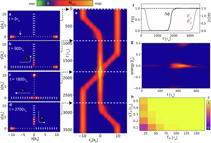
a–d Spatial plot of the zero-energy Nneq during consecutive times in the gate operation. White arrows (dots) indicate antiferromagnetic in-plane (ferromagnetic out-of-plane) alignment of the magnetic moments. Blue area indicates the superconducting substrate. e Majorana world lines obtained from a projection of the zero-energy Nneq onto the real space x-axis. f Time dependence of the fidelity Fe,o(t) for the even and odd parity states and of the geometric phase difference Δϕ. g Time- and energy-dependent Nneq at a site of the MSH network (see yellow arrow in (a)). h Fidelity F as a function of TR and ΔTR. Parameters are (μ, α, Δ, JS) = (−3.993, 0.9, 2.4, 5.2)te with a difference of ΔJ = 0.26te in the magnetic coupling between alternating sites on the T-structure, (TR, ΔTR) = (500, 50)τe and Γ = 0.01te for the inverse quasi-particle lifetime. These parameters, resulting in a topological superconducting gap of Δt ≈ 0.4te, were chosen in order to minimize (i) the localization length of the MZMs along the network, and thus (ii) the hybridization between the MZMs. Total system size for all results is 600 sites with dimension (20a0 × 30a0).
The time dependence of the fidelity Fe,o(t) during the entire gate process is shown in Fig. 2f. Due to the evolving magnetic structure, Fe,o(t) deviates from unity after the start of the gate process, quickly reaching nearly zero due to the approximate orthogonality between the initial many-body state at t = 0 and that at t. However, at the end of the gate process, when the initial magnetic structure is re-established, the fidelity returns to unity, demonstrating the adiabaticity of the braiding process. As a result, the geometric phase Δϕ reaches 3π/2 at the end of the process (see Fig. 2f), establishing the fractional statistics of the MZMs. The adiabaticity of the process is also reflected in the energy- and time-resolved Nneq at a given site in the system (see Fig. 2g), which demonstrates that as the MZM moves through a site, it remains well separated in energy from the bulk states, thus ensuring a fidelity of unity. Finally, in Fig. 2h, we present the fidelity as a function of rotation time TR and delay time ΔTR, which defines the time regime necessary to observe an adiabatic process. We note that while a measurement of dI(V, r, t)/dV visualizes the spatial braiding of the MZMs, the actual gate process for the purpose of implementing quantum algorithms should of course be realized without a simultaneous measurement of dI(V, r, t)/dV, as the presence of a tunneling current will likely lead to quasi-particle poisoning and decoherence. In contrast, the use of an ESR-STM tip to rotate the spins is not expected to lead to quasi-particle poisoning and decoherence as no tunneling current is required34, and the tip can be located a few lattice spacings away from the rotated spin and hence from the MZM22,23,24,25.
Simulation of a σ
z-gate
We next implement a σz-gate, using the MSH loop structure of Fig. 1b. In the initial (t = 0) configuration, the MZMs are localized in the upper right and lower left corners of the loop (see Fig. 3a), at the ends of the topological (ferromagnetic) segment in the loop’s lower right half. We realize a σz-gate by moving the MZMs once around the entire loop structure (the time-dependent gate protocol is given in the Methods Section). The resulting zero-energy Nneq together with the corresponding magnetic configuration is shown in Figs. 3a–d for consecutive times during the gate operation (the full time dependence of Nneq during the entire gate process is shown in Supplementary Movie 3). After the end of the gate process, Nneq exhibits the same spatial structure as in the initial configuration (see Fig. 3a). The MZMs’ world lines (see Fig. 3e), shown as a projection of the zero-energy Nneq onto the diagonal axis (see dashed yellow line in Fig. 3a), reveal the double exchange of the MZMs in space and time (a 3D rendering of the world lines is presented in Supplementary Movie 4). The adiabaticity of the process, as demonstrated by Fo reaching unity at the end of the gate process (see Fig. 3f), then implies a change in the geometric phase of Δϕ = π. Note that after half of the gate operation at time t1/2, the two MZMs have been exchanged, which realizes a (sqrt{{sigma }_{z}})-gate, similar to the case of Fig. 2. However, while the geometric phase Δϕ at this point has as expected changed by π/2 (Fig. 3f), the corresponding fidelity is zero. The latter, however, is not a reflection of the non-adiabaticity of the process, but of the fact that the initial spin configuration (Fig. 3a), and that at time t1/2 differ significantly (Fig. 3c). Indeed, the adiabaticity of the gate process is again reflected in the energy and time dependence of Nneq at a site in the loop (see Fig. 3g), which demonstrates that the MZM and the bulk states remain well separated in energy during the gate process. To contrast this, we consider a 10-times faster gate operation: while in this case, the fidelity Fo = 0.98 is only slightly reduced from unity (Fig. 3h), the geometric phase deviates already strongly from the expected value of ± π, clearly revealing the breakdown of adiabaticity. This is further confirmed by a plot of Nneq (see Fig. 3i) that reveals a strong overlap in energy between the MZM and bulk states. We thus conclude that in addition to the fidelity, Nneq reflects the adiabaticity, or lack thereof, of the gate operation, thus providing an experimentally measurable signature of the success or failure of the gate process, even without the readout of the qubit state.
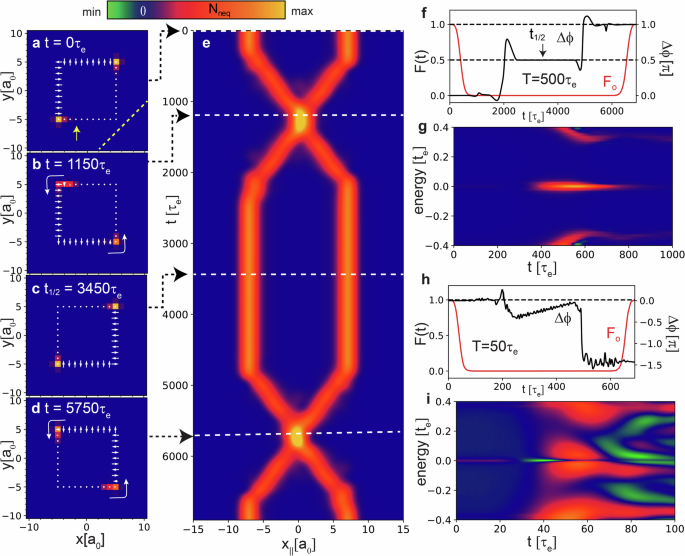
a–d Spatial plot of the zero-energy Nneq during consecutive times in the gate operation. e Majorana world lines, as obtained from a projection of the zero-energy Nneq onto the dashed yellow line in (a). f Fidelity of the odd parity many-body wave function and geometric phase as a function of time. g Time- and energy-dependent Nneq at a site in the MSH network (see yellow arrow in (a)). For all results (TR, ΔTR) = (500, 100)τe. h, i Same as (f, g) but for a 10 times faster gate operation with (TR, ΔTR) = (50, 10)τe. Parameters are (μ, α, Δ, JS) = (−3.993, 0.9, 2.4, 5.2)te, and Γ = 0.01te. Total system size for all results is 441 sites with dimensions (21a0 × 21a0).
Simulation of a σ
x-gate
Finally, to implement a one-qubit σx-gate we consider an MSH system consisting of two intersecting loops of magnetic adatoms, as schematically shown in Fig. 4a. In each loop, a pair of MZMs, labeled α, β and γ, δ, are localized at the ends of their respective ferromagnetic, and hence topological, segments (shown in green). The many-body wave functions in the even and odd parity sector are built as schematically shown in Fig. 4b with ({leftvert Omega rightrangle }_{{rm{gs}}}) being the many-body ground state wave function. Due to the finite hybridization of the MZMs within each pair, their respective energies are small, but non-zero (see Fig. 4b). The σx-gate operation, transforming the two states within each parity sector into one another, is implemented as shown in Figs. 4c–h, where we present spatial plots of the zero-energy Nneq for consecutive times during the gate process (the time-dependent gate protocol is given in the Methods section, and the full time dependence of Nneq is shown in Supplementary Movie 5). The resulting Majorana world lines (Fig. 4i), obtained by projecting the zero-energy Nneq onto the real space axis indicated by the dashed yellow line in Fig. 4c, visualize the gate operation, and in particular the double exchange of the β and γ MZMs in time and space (a simplified braiding diagram of the gate process is shown in the inset, and a 3D rendering of the world lines is presented in Supplementary Movie 6). To evaluate whether the braiding of MZMs shown in Figs. 4c–h indeed constitutes a σx-gate, we compute the success probabilities for a successful completion of the gate process (i.e., at the final time t = tf) via
with i, j = 0, 1, (leftvert ij(t)rightrangle) is the time-evolved many-body wave-function with (leftvert ij({t}_{i})rightrangle =leftvert ijrightrangle) at the beginning of the gate process, i.e., at initial time t = ti, and ({p}_{ij}^{s}=1) implies a successful implementation of the σx-gate ((leftvert ij(t)rightrangle) is the full many-body wave function of the entire system with 484 sites). In Figs. 4j, k, we present ({p}_{ij}^{s}) as a function of the rotation time TR in the even and odd parity sectors, respectively (the small TR limit is shown in Supplementary Note 1). It was previously suggested5,15,33,35 that the oscillatory dependence of ({p}_{ij}^{s}) on TR is due to a finite energy splitting, ΔE, between the two many-body states within each parity sector (see Supplementary Note 2) arising from a non-zero hybridization between the MZMs, and not related to transitions between the Majorana zero modes and trivial bulk states. The latter is supported by the observation that the total transition probability within the Majorana sector ({p}_{ij}^{tot}={p}_{ij}^{s}+{p}_{ij}^{f}), where ({p}_{ij}^{f}=| langle ij({t}_{f})| ijrangle {| }^{2}) is the failure probability, is unity (see dotted lines in Figs. 4j, k). Thus, the maximum success probabilities of ({p}_{00}^{s}=0.993) and ({p}_{01}^{s}=0.999) (see black arrows in Figs. 4j, k) can only be achieved for specific rotation times, TR. Since the corresponding failure rates of ({p}_{00}^{f}=0.007) and ({p}_{01}^{f}=0.001), respectively, are below the threshold Pauli error rates pth ≈ 0.01 for error correction36,37, these cases nevertheless represent successful realizations of a topological σx-gate. Finally, assuming a typical value of te = 100 meV, we find that the total gate operation times (see upper x-axes in Figs. 4j, k) extend into the 100 picosecond range, reaching one nanosecond for some gate operations (see below). Thus, the theoretical formalism employed here (see Methods Section and ref. 21) allows us to study the realizations of quantum gate operations from a few femto- to the nanosecond range, thus spanning six orders of magnitude in time.
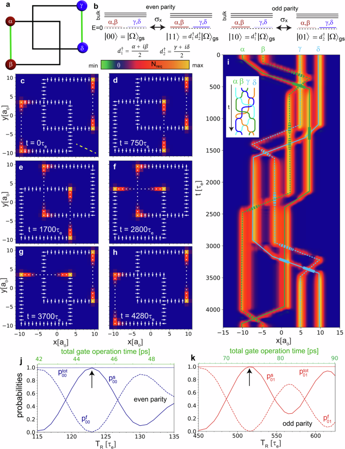
a Schematic picture of the σx-gate in an MSH system, consisting of two intersecting loops of magnetic adatoms, and two pairs of MZMs. b Effect of the σx-gate on the even and odd parity many-body wave functions. c–h Spatial plot of the zero-energy Nneq at successive times during the gate process. i Majorana world lines of MZMs α – δ (see (a)), as obtained from a projection of the zero-energy Nneq onto the axis depicted by the dashed yellow line in (c). Whenever two Majorana world lines cross, the one in front is indicated by a thick line. The inset shows the corresponding (simplified) braiding diagram of the gate process. Success and failure probabilities within the (j) even parity sector with μ = −3.5te, ΔTR = 0.2TR, and (k) odd parity sector for μ = −3.45805te, ΔTR = 0.1TR. For all other panels, parameters are (μ, α, Δ, JS) = (-3.5, 0.9, 2.4, 5.2)te, (TR, ΔTR) = (100, 20)τe, and Γ = 0.01te.
Spatial symmetries and the σ
x-gate
The oscillatory behavior of ({p}_{ij}^{s}), which is not unique to the MSH system discussed here, but has also been reported in the study of vortex systems15,33 and semi-conducting nano-wires5,35, represents a significant experimental challenge in the realization of topological quantum gates, as it would require the fine-tuning of the rotation time.
To overcome this challenge, it is necessary to reduce or eliminate the energy splitting between the many-body states, which would hence increase the oscillation period ~ ℏ/ΔE and thus render ({p}_{ij}^{s}) much less sensitive to changes in TR. We propose two different approaches to achieve this goal. The first and obvious approach is to increase the distance between the MZMs, as the hybridization and hence the energy splitting ΔE, decreases exponentially with the distance between the MZMs, with the characteristic length scale set by the superconducting coherence length, ξc, along the network direction. While we cannot consider 2D MSH system sizes that are larger than the ones shown in Fig. 4, we can test this idea by implementing a σx-gate in a 1D T-structure, as shown in Fig. 5a, with the world lines shown in Fig. 5b reflecting the gate protocol. We find that the oscillation period of ({p}_{ij}^{s}) significantly increases with increasing distance d (and hence decreasing hybridization) between the MZMs, as shown in Fig. 5c for the even parity sector, and as exemplified for d = 36a0 in Fig. 5d (we note that for this case, the total gate operation time exceeds 1ns). In particular, by changing the distance from d = 11a0 in the gate architecture of Fig. 4 to a distance of d = 36a0 in the gate architecture of Fig. 5a, the oscillation period is increased from Tosc ≈ 14τe to Tosc ≈ 7000τe, i.e., by a factor of 500 (a similar increase is also found in the odd parity sector). While this approach is thus quite successful in increasing the oscillation period, given the large coherence length of many s-wave superconductors38, this approach would likely require to build and coherently control gate sizes of the order of hundreds of nanometers, which, by itself, represents a significant experimental challenge. We thus propose a second approach to eliminating the energy splitting ΔE that utilizes the spatial symmetries of an MSH system, such as the box-and-whisker structure shown in Fig. 5e. Such a system allows one to preserve a spatial point symmetry around C (see Fig. 5e) at any point during the gate process, as reflected in the symmetric world lines shown in Fig. 5f. This point symmetry guarantees that the energy splitting between the odd parity (leftvert 01rightrangle) and (leftvert 10rightrangle) states is identically zero, thus completely eliminating the oscillatory behavior in ({p}_{ij}^{s}) of the odd parity sector, as shown in Fig. 5g. While preserving the point symmetry does not affect the oscillations in the even parity sector (Fig. 5h), this approach provides the proof of concept that invoking additional symmetries of the MSH system can facilitate the realization of topological quantum gates. Clearly, future studies are required to further elucidate the role played by spatial or other symmetries in the effective implementation of gate protocols.
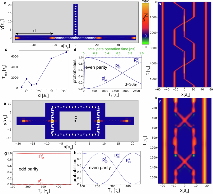
a Spatial plot of the zero-energy Nneq at t = 0 in the MSH T-structure, showing the two topological regions, left and right of a trivial T-segment, with d denoting the spatial distance between the Majorana zero modes within one pair. Blue and gray areas indicate the presence and absence, respectively, of a superconducting substrate. b Majorana world lines, as obtained from a projection of the zero-energy Nneq onto the x-axis. c Oscillation period of the success and failure probabilities within the even parity sector as a function of distance d between the two MZMs within each pair (see panel (a)). d Success and failure probabilities within the even parity sector as a function of TR with ΔTR = 0.2TR for d = 36a0.For (a–d), parameters are (μ, α, Δ, JS) = (−4, 0.45, 1.2, 2.6)te, and for (b) (TR, ΔTR) = (100, 20)τe. e Spatial plot of the zero-energy Nneq at t = 0 in the MSH box-and-whisker structure, showing the two topological regions, left and right of the box. f Majorana world lines, as obtained from a projection of the zero-energy Nneq onto the x-axis. Success and failure probabilities in the (g) odd and (h) even parity sectors as a function of TR with ΔTR = 0.2TR. For (e–h), parameters are (μ, α, Δ, JS) = (-3.97, 0.9, 2.4, 5.2)te, and for (f) (TR, ΔTR) = (120, 24)τe and Γ = 0.01te.
Discussion
We have demonstrated the feasibility of MSH systems as a new platform for the implementation of topological (sqrt{{sigma }_{z}})-, σz-gates, and σx-quantum gates. Using a novel theoretical formalism we recently developed21, we computed the time-dependent many-body wave functions in MSH systems with as many as 600 sites, allowing us to obtain the gates’ success probabilities in experimentally relevant 2D systems for total gate operation times ranging from the few femto- to the nanosecond scale, thus spanning six orders of magnitude in time. We proposed a novel braiding mechanism in which the spatial motion of MZMs is achieved through a manipulation of the MSH system’s magnetic structure. The feasibility of such a magnetic manipulation at the required lattice scale has recently been demonstrated in magnetic dimers and trimers22,23,24,25 using ESR-STM techniques. Moreover, we showed that quantum gates in MSH systems can be realized in different MSH architectures such as the (sqrt{{sigma }_{z}})-, and σz-gates in the architectures of Figs. 2 and 3, or the σx-gate in the double-loop, T-, or box-and-whisker architectures shown in Figs. 4 or 5. We note that the implementation of quantum gates in the above double-loop structure, or generalizations thereof, possesses the great advantage that any two MZMs can be braided directly (in contrast to the previously considered T-structures), which could be of potential benefit for the realizations of more complex quantum algorithms. We identified experimentally relevant challenges in the implementation of topological gates, such as the oscillatory dependence of the gates’ success probabilities on the characteristic time TR, arising from a finite hybridization between the MZMs, and proposed solutions which, e.g., make use of the spatial symmetries of the gate process. Finally, we showed that the gate operation can be visualized via the time-, energy-, and spatially resolved non-equilibrium density of states26, Nneq, which can be measured via the time-dependent differential conductance, dI(V, t)/dV in STS experiments27,28. This also allowed for the first time to image the Majorana world lines in time and space. Our results thus represent the proof of concept that a combination of atomic manipulation techniques to quantum engineer MSH structures, and of ESR-STM techniques to implement gate protocols, yields a versatile platform for realizing topological quantum gates in MSH systems.
An important question remains as to the experimental realization of the braiding scheme proposed here. In order to experimentally execute the braiding process described above, it is necessary that the ESR-STM spin-flip time be much smaller than the spin coherence times, i.e., the time scale over which the spins remain in a coherent magnetic alignment. For spin dimers, the time scale for spin-flip processes in ESR-STM experiments is currently on the order of 20ns, while the spin coherence time is approximately 86ns22. However, the spin-flip time can plausibly be further reduced by factors of 10-100 by increasing local magnetic fields, for example, through the use of additional magnetic impurities34. Such a reduction would still preserve the adiabaticity for the gate operation (see above). In addition, it was shown that the spin coherence times can be increased by 4-5 orders of magnitude for spins located on superconducting surfaces39 (rather than on metallic surfaces as in refs. 22,23,24,25) since the low energy fermionic degrees of freedom giving rise to decoherence are gapped out. This could plausibly render the spin coherence anywhere between 5 and 7 orders of magnitude larger than the spin-flip time, which would be sufficient to perform the gate operations discussed above. Moreover, the rotation of individual magnetic moments in ESR-STM experiments was achieved remotely over distances of several lattice constants23. The spatial extent of this remote driving is in general only limited by the extent of the RF field, Lrf: if it is sufficiently large, i.e., comparable to the spatial size of the MSH networks discussed, it might be possible to perform an entire gate operation without the necessity to move the STM tip. This of course would require that the magnetic adatoms in the MSH network possess different resonance frequencies (which can be realized by using different magnetic adatoms or creating different magnetic environments23,24,25) and thus can be independently rotated. While details concerning the efficient balance between moving the STM tip, the extent of Lrf, and the ability to realize different resonance frequencies are beyond the scope of our theoretical study, we demonstrated above that topological MSH networks consisting of more than one type of magnetic adatoms can be created, thus providing the proof of concept for the applicability of remote driving in MSH networks.
Finally, several open theoretical questions remain as well. First, how can one initialize these topological gates in specific qubit states, and read out qubit states after the end of the gate operation? Second, how are the results described above, and in particular the transition probabilities, affected by quasi-particle poisoning and/or disorder? And finally, is it possible to implement quantum gates in more dilute magnetic networks? The latter would eliminate the effects of a direct exchange interaction between the magnetic adatoms and likely facilitate the use of ESR-STM techniques22,23,24,25 to manipulate the local electronic structure. While preliminary work investigating these questions further supports the feasibility of MSH systems for the implementation of topological quantum gates and algorithms, their answers require some detailed discussions and will therefore be reserved for forthcoming publications.
Methods
Theoretical formalism
Construction of ground-state wave-functions
The Hamiltonian in Eq. (1) of the main text can be recast into the Bogoliubov de Gennes (BdG) form
with HBdG possessing a particle-hole symmetry, as reflected in ({H}_{{rm{BdG}}}=-{tau }_{x}{H}_{{rm{BdG}}}^{* }{tau }_{x}), where τx is a Pauli matrix. At t = 0, the Bogoliubov transformation,
diagonalizes the Hamiltonian as
where En≥0. The ground state is the quasiparticle vacuum, (leftvert Omega rightrangle), such that ({d}_{n}leftvert Omega rightrangle =0) for all n. We construct the quasiparticle vacuum as a product state2,30,40. This is done by annihilating all quasiparticles from the true c-particle vacuum.
The normalization is given by ({mathcal{N}}=| det (V)|). The degenerate ground states are thus
Time evolution of states
We define
where ({mathcal{U}}(t)) is the unitary time evolution operator,
Using the time-dependent BdG equations8,15,33, the time-evolved operators are given by
where
We can now write the time-evolved ground states
The time-evolved quasiparticle vacuum is given by
The normalization is given by ({mathcal{N}}(t)=| det (V(t))|). The phase α(t) arises from the evolution of the true vacuum. However, this phase is gauged away in our gauge-invariant formulation of physical quantities, such as the geometric phase.
Overlaps between states
For states (leftvert psi rightrangle ,leftvert {psi }^{{prime} }rightrangle in {leftvert 00rightrangle ,leftvert 01rightrangle ,leftvert 10rightrangle ,leftvert 11rightrangle }), the overlaps have the form
The minus sign is due to reversing the order of the operators in (leftlangle {psi }^{{prime} }rightvert) and (s=({n}_{1}^{{prime} }+{n}_{2}^{{prime} })({n}_{1}^{{prime} }+{n}_{2}^{{prime} }-1)/2+N(N-1)/2). The vacuum overlap can now be calculated using Wick’s theorem41,42,
The matrix M is an anti-symmetric matrix constructed from the contractions between operators, and pf( ⋅ ) is the Pfaffian. The resulting matrix is41,43,44
Note that rows and columns corresponding to unoccupied modes must be truncated41. The lower triangle is found using anti-symmetry. For transition probabilities, Eq. (18) simplifies to
Time-dependent gate protocols
To implement time-dependent gate protocols, we introduce the function
which (as shown below) describes the rotation of a spin from a polar angle of θ = 0 to π/2 over a rotation time TR, starting at time t0. This function was chosen as it guarantees a smooth evolution of the polar angle from 0 to π/2. Here, we use spherical coordinates to describe each spin’s orientation in space, such that
The azimuthal angle ϕ is measured with respect to the x-axis. Below, we also introduce ΔTR as the delay time between the start of a spin rotation at one site, and that on the next site, and ΔTwait denotes a pause at certain steps in the gate process, which allows the system to equilibrate.
Gate protocol for implementing a (sqrt{{sigma }_{z}})-gate in the T-structure
To implement a (sqrt{{sigma }_{z}})-gate in the MSH T-structure of Fig. 2 in the main text, we number the sites of the magnetic adatoms from 1 to 2Nx + 1 along the horizontal segment, where Nx is the length of one leg of the T-structure and from 2Nx + 1 to 3Nx along the vertical segment. The time dependence of the azimuthal and polar angles of the spins in the network are then given by
Gate protocol for implementing a σ
z-gate in the MSH loop-structure
In the MSH loop structure, we label the magnetic adatoms starting from the lower left corner as 1 and go counter-clockwise up until 4Nx, where Nx + 1 is the number of adatoms on one side of the square. By rotating a spin adjacent to the topological region from an in-plane to an out-of-plane alignment, and then rotating a spin at the other end of the topological region from an in-plane to an out-of-plane alignment, we move the topological region by one site, while leaving its length unchanged. Repeating this until the topological region returns back to its initial placement in the loop, a σz gate is executed. The azimuthal and polar angles for the spins of these 4Nx magnetic adatoms are given as a function of time by
Gate protocol for implementing a σ
x-gate in the MSH double loop-structure
In order to implement a σx-gate in the MSH double loop structure shown in Fig. 3 in the main text, we label the adatom sites from 1 to 8Nx, where Nx + 1 is the number of adatoms along one side of each square. The sites 1 to 4Nx are on the lower left square, starting from the lower left corner going counter-clockwise, and the sites 4Nx + 1 to 8Nx are on the upper right square, again starting at the lower left corner and going counterclockwise. The crossings of the two squares occurs at sites Nx + 1 + d and 3Nx + 1 − d in the first square and at sites 5Nx + 1 − d and 7Nx + 1 + d in the second square, where d is both the horizontal and vertical distance from the lower left corner of the first square to the lower left corner of the second square. Like in the σz-gate, both topological regions are moved around their respective loop once; this is achieved by rotating a spin adjacent to the topological region from an in-plane to an out-of-plane alignment, and then rotating a spin at the other end of the topological region from an in-plane to an out-of-plane alignment, thus moving the topological region by one site, while leaving its length unchanged. The azimuthal and polar angles of the gate process are then given by
For the two crossing points of the squares we defined


Responses