Spin-orbit control of antiferromagnetic domains without a Zeeman coupling

Introduction
Antiferromagnetism is preponderant among magnetically ordered materials. This type of ordering, defined by an antiparallel alignment of elementary magnetic moments, assumes a multitude of variations3,4, including collinear and non-collinear antiferromagnets, modulated structures such as spin-density waves (SDW) and antiferromagnetic spin glasses4. Yet, despite the fact that we explore antiferromagnetic ordering for almost a century, the fundamental mechanisms for controlling antiferromagnetic states among different types of domains and orders remain challenging5,6. Establishing control and detection of antiferromagnetic domains open new windows of opportunity for both fundamental research and applications1,7.
In the era of information and data science, spintronics has become a topic of intense research, since it offers the possibility of obtaining non-volatility, reduced power consumption, increased data processing speed, and high density magnetic memories8. In this field, antiferromagnets have several advantages over ferromagnetic materials, as they possess ultrafast spin dynamics1,9,10,11,12,13 and small or non-existent stray fields1,7,12. The terahertz control of the spin degree of freedom enables high speed data processing12,13. The absence of stray fields makes these materials robust against magnetic perturbations1, offering the possibility of obtaining even higher density information storage when antiferromagnets are utilized in active components of spintronic devices. However, higher robustness has also meant that it has been more difficult to manipulate different binary states and detect them. The efficient manipulation6 and detection1,7 of AFM domains are among the most pressing problems to be solved.
Direct manipulation of AFM domains through the application of a strong magnetic field often relies on the Zeeman coupling term (H ⋅ μ, where μ indicates the direction of the ordered moments) and therefore on the relative orientation between the applied field and the spin orientation. An example is found in elemental chromium, where a single magnetic domain (single k-domain) state in a transverse SDW can be obtained through the application of a sufficiently large field14,15. On the detection side, beyond utilizing optical and scattering techniques16, probing domain states in the charge channel is essential for applications7. Charge-detection of different antiferromagnetic states in bulk materials, i.e., the AFM-based anisotropic magnetoresistance (AMR), often relies on electronic scattering on domain walls17,18 or a change in the density of states near the Fermi level due to the opening of a gap-type antiferromagnetism (as in chromium19,20) or relativistic spin-orbit coupling21,22. In the latter, distinctive resistive states arise due to the anisotropy of the electronic structure when the AFM moments are aligned along different crystallographic directions21. In fact, most of the explored effects involve the spin orientation either in the manipulation or the detection of AFM states. However, in most cases, the outcome from each of the effects above trigger small readout signals that are incompatible with the scalability of devices1,7,23. Thus, new conceptual and experimental advancements on how to manipulate and detect AFM domains are required. Finding ways to decouple the spin orientation from magnetoelectronic phenomena could offer easier ways to manipulate and detect AFM domains.
In this context, we focus on a recent theoretically proposed mechanism suggested to occur in centrosymmetric multiband metals with large spin-orbit coupling (SOC)2. A spin susceptibility anisotropy was predicted to arise from interband spin-orbit coupling2 in a similar manner to what is observed in non-centrosymmetric materials24. In the latter, Rashba-type interactions are of key importance for spintronics applications7,25, because it introduces a non-trivial SOC which results in an anomalous anisotropic spin susceptibility26. Instead, in centrosymmetric materials, it is the multiband nature of the electronic structure which is responsible for such anisotropy, providing a mutual coupling between the AFM ordering vector and the field direction2. The theoretical model anticipates that, for a magnetic structure where several k-domains are allowed by the crystal structure, interband SOC gives rise to a static susceptibility χ(k, H) that is largest either at k∥H or k⊥H, for fields applied transversely to the moment direction2. Therefore, a rotation of the magnetic field direction in the plane perpendicular to the moments becomes a way to manipulate the AFM domains (see Fig. 1(a) and (b)). The proposed mechanism is an intrinsic electronic effect present in antiferromagnetic materials that does not depend on a Zeeman term and has not been fully experimentally validated or explored yet. The SOC model2 was proposed to explain the domain selection in CeCoIn527 and unlike other models considered in that context, it does not rely on a superconducting ground state28,29,30.

a schematic diagram of the k-domains in the sample along with their amplitude modulated magnetic structures. The orange and blue arrows indicate the direction of the static magnetic moments (μ) pointing along the [001] direction and modulated with two orthogonal ordering vectors k+ and k−. The static moments are located on the rare earth site, indicated by the orange balls. Blue and green balls indicate the In and Co ions. A high resolution version of the spin structures is available in the Supplementary Fig. 1. b Shows the k+ and k− domains. As the field is rotated in the ab-plane across the [100] crystallographic direction, the SDW domains switch, favoring the domain whose modulation is most perpendicular to the field direction. c The scans display the diffracted neutron intensity in counts per 16 minutes along (q, ± q, 0.5) in (r.l.u.). d Temperature dependences of the magnetic Bragg peak intensities of the two magnetic domains measured at μ0H = 1 T in zero field cooled (ZFC) and field cooled (FC) conditions. The green data points (BG) indicate the background intensity obtained in the paramagnetic state.
Results
Magnetic structure and domain population control by field cooling
Recently, the emergence of itinerant antiferromagnetism has been observed in the large spin-orbit coupled multiband compounds NdxCe1−xCoIn5 with x ≤ 0.2531,32,33. These compounds crystallize in the centrosymmetric tetragonal structure with space group P4/mmm31. The degeneracy of the tetragonal structure allows for two k-domains in the SDW phase, which are indeed confirmed32. The magnetic moments point along the tetragonal c-axis with an amplitude that is modulated along two orthogonal directions in the ab-plane (see Fig. 1a). The superconducting state of the parent compound, CeCoIn5, hosts a SDW with the same magnetic symmetry27. There, the population of k-domains completely switches upon rotation of the magnetic field within only ~0.1o 27. However, since the AFM phase in the pure compound is exclusively present in the zero-resistive state, magnetoresistive effects cannot be investigated. In addition, the origin of this phenomena is indistinguishable from scenarios where a coupling between magnetism and superconductivity27,34 is essential. Experiments on Nd0.05Ce0.95CoIn5 have revealed a low and a high field SDW phase which are only differentiated by their domain switching behaviour35. The results presented in there and the observation that the antiferromagnetism develops independent of the superconducting state under Nd substitution32 motivated us to fully explore the aforementioned proposed phenomenon.
The magnetic structures of NdxCe1−xCoIn5 spontaneously form two equally populated k-domains at zero magnetic field. The real space representation of the two k-domains is depicted in Fig. 1b. In reciprocal space, these two domains are described by two subsets of k-vectors forming an eightfold star (see Supplementary Fig. 1). By mirror and translational symmetry operations, the eight vectors are attributed to either k+ or the k− domains of form (q, q, 0.5) and (q, −q, 0.5), respectively. Figure 1c shows neutron diffraction data for wavevectors along the (q, ± q, 0.5) direction at low temperature and zero magnetic field for Nd0.17Ce0.83CoIn5.
Figure 1 d displays the temperature dependence of the magnetic Bragg peak intensity at μ0H = 1 T along the ([1overline{1}0]) direction in zero field (ZFC) and field cooled (FC) conditions. After zero field cooling, both domains reveal equal intensity below the Néel transition temperature TN. Field cooling influences the domain formation, enhancing the intensity of the domain oriented perpendicular to the field direction, i.e., k+ for ({{boldsymbol{H}}}parallel [1overline{1}0]). Thus, the domain population can be controlled upon magnetic field without a Zeeman coupling.
Phase diagram and magnetic domain selection
Figure 2 displays the HT-phase diagrams of Nd0.1Ce0.9CoIn5 and Nd0.17Ce0.83CoIn5. In Nd0.1Ce0.9CoIn5, magnetic order develops below a Néel temperature that is lower than the superconducting transition temperature Tc, but exists up to fields higher than the superconducting upper critical field Hc2. Upon further increasing the Nd content to 17%, superconductivity is completely enclosed by the magnetic phase. Thus, NdxCe1−xCoIn5 with 0.25 ≥ x ≥ 0.1 is a regime where magnetic order is developed in the absence of superconductivity (see Supplementary Note II for x = 0.25 and also field dependences shown in Fig. 3), providing an ideal test ground for theories assessing the SDW domain repopulation in the absence of a Zeeman coupling. This also allows us to clarify the role of superconductivity in this process.
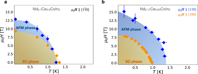
HT-phase diagram of (a) Nd0.1Ce0.9CoIn5 and (b) Nd0.17Ce0.83CoIn5. The magnetic phase boundaries were obtained from temperature and field scans of the Bragg reflection intensities. The superconducting phase boundaries were measured by electrical resistivity measurements.
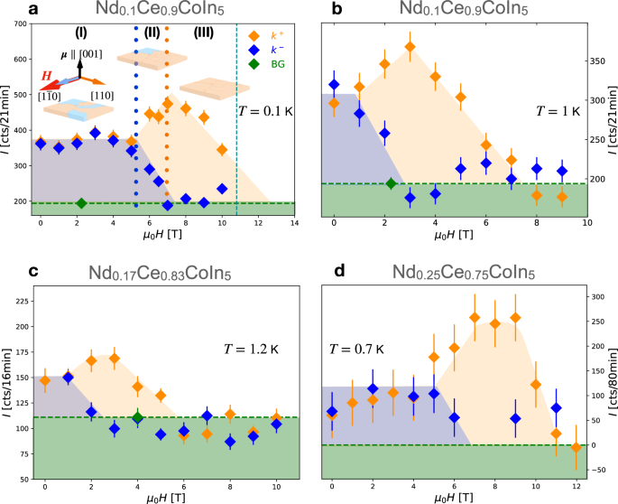
Magnetic Bragg peak intensity as a function of field along the ([1overline{1}0]) direction at different temperatures for Nd0.1Ce0.9CoIn5 (a, b), in the normal conducting state of Nd0.17Ce0.83CoIn5 (c) and for the correlated metal Nd0.25Ce0.75CoIn5 (d). BG indicates the background, measured in the paramagnetic states of NdxCe1−xCoIn5. The rectangular prisms displayed in (a) are a schematic view of the sample showing the evolution of the domain population. At low fields (regime I), both k+ and k− domains are present with equal population. In regime II, a domain repopulation takes place, favoring the domain which is mostly perpendicular to the field direction, i.e., k+. In regime III, a single k+ domain state is obtained. The vertical green line in (a) indicates the field where we have performed complementary electrical resistivity measurements (see Figs. 4 and 5).
For this purpose, we studied the evolution of the k-domain population as a function of magnetic field along the ([1overline{1}0]) direction. Figure 3 displays the field dependences of magnetic Bragg peak intensities associated with the two domain states k+ and k− for the 10%, 17% and 25% Nd substituted compounds. We find a field-induced domain imbalance of the k-domains, i.e., above a certain field, the intensity of the unfavored k−-domain drops to zero while the intensity of the k+ domain is increased. Remarkably, this happens in the absence of superconductivity (Fig. 3c, d), and is indistinguishable from the domain selection in the superconducting state. Thus, our results establish that superconductivity is not necessary for the domain repopulation. The domain selection is not reversible with the removal of the magnetic field (see Supplementary Note III). We note that the unfavored k−-domain is only formed when the system is reinitialized through zero field cooling or by in-situ rotation of the magnetic field direction. This demonstrates that the AFM phase has a non-volatile memory effect. Note that non-volatility is a key asset for magnetic recording and it has been seldom reported in the literature for antiferromagnets36, and antiferromagnetic metals in particular.
Anisotropic magnetoresistance
If the mutual dependence of the magnetic wavevector on the field direction indeed originates from an interband spin-orbit interaction, as suggested by theory, the effect should also be observable in transport properties. Therefore, we carried out experiments on the charge-detection of the SDW switching. Notably, we explored the magnetotransport effect of Nd0.1Ce0.9CoIn5, for which a relatively large area of the SDW phase is observed in absence of superconductivity. Resistivity measurements were performed under a configuration where the electrical current was intentionally misaligned 14o to the [110] direction in the ab − plane. This allowed us to distinguish scenarios where the magnetoelectronic effect is purely related to the magnetic structure or to the relative orientation between the electrical current and the field. As the magnetic field is rotated, the SDW modulation alternates from being mostly perpendicular to being mostly parallel to the current direction (see Fig. 4a). In Fig. 4b, we depict the angular dependence of the magnetoresistance ratio defined as Δρ/ρ⊥ = [ρ(θ) − ρ⊥]/ρ⊥, where ρ⊥ is the transverse magnetoresistance, i.e., the resistivity value when the current is applied perpendicularly to the magnetic field direction. The angular scans were obtained in zero field cooling conditions and the field was applied first close to the symmetrically equivalent ([0overline{1}0]) direction. Note that the two domains are degenerate for fields applied along [010] and [100], because k+ and k− have equal components parallel to the field direction (see Supplementary Note I). Hence, these directions do not favor any domain and are called symmetrically equivalent. Δρ/ρ⊥ at T = 1.5 K > TN displays a two-fold symmetry with a resistance minimum for J∥H and a large magnetoresistance for J⊥H. This is due to the cyclotron effect and is expected for metals37,38. Under the application of a magnetic field, the charge carriers are subjected to a Lorentz force that modifies the electronic trajectories. When the current is applied perpendicularly to the field direction, the Lorentz force is maximal and a longer electronic path results in an increased resistance (see also Supplementary Note V). The similarity of the low and high temperature magnetoresistance anisotropy at field directions close to θ = − 90o indicate that the Lorentz force dominates the scattering process in this angular range. The low temperature anisotropic magnetoresistance (AMR) measured below TN at T ≈80 mK is superimposed on the high temperature data. We found an additional contribution to the resistivity for fields applied along the [±1 ±10] crystallographic directions. These peaks are present at temperatures below the AFM transition (see Fig. 4c) and are directly related to the emergence of antiferromagnetism in Nd0.1Ce0.9CoIn5 (see Fig. 5).
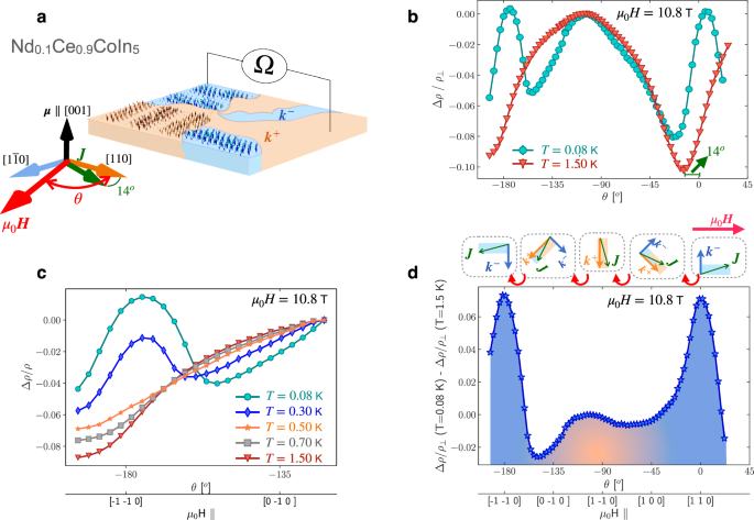
a The electrical resistivity was measured along the J∥[110] direction with a misalignment of 14o in the ab − plane. As the field is rotated across the [100] crystallographic direction, the SDW domains switch, thus changing the relative orientation between the current direction and the SDW modulation. b Angular dependence of resistivity normalized by the transverse resistivity for T < TN (green) and T > TN (red) at μ0H = 10.8 T. The high temperature curve resembles the cyclotron effect observed up to temperatures higher than 20 K (Supplementary Note V). At low temperatures, an increased resistivity is found for H∥[110], i.e. when the current is perpendicular to the k+ or k− domain. c Angular dependence of the electrical resistivity normalized by the value at θ ≈ −120o and μ0H = 10.8 T for different temperatures. We observe a resistivity enhancement below the antiferromagnetic transition. d Angular dependence of the AFM AMR where the paramagnetic contribution has been subtracted. In the schematic diagram, k represents the ab-plane components of the two-domains.
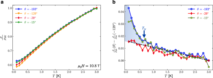
a Temperature dependence of electrical resistivity inside the antiferromagnetic phase for different magnetic field orientations. b The difference of the normalized resistivities at various field orientations with respect to the normalized resistivity at θ = −128o shows that additional anisotropic magnetoresistance develops only inside the antiferromagnetic phase. The background level is obtained via linear regression of all three resistivity curves at temperatures larger than 0.7 K and extrapolated to low temperatures.
Figure 5a displays the normalized resistivity as a function of temperature, where the normalization at T = 3 K integrates out the paramagnetic cyclotron effect. Figure 5b shows the difference between the normalized resistivities plotted in Fig. 5a and the normalized resistivity at θ = −128o. Their subtraction ρ(θ) − ρ(θ = −128o) reveals the origin of the resistivity enhancement attributed to the peaks shown in Fig. 4b, c. Figure 5b provides evidence for a dramatic resistivity increase below the antiferromagnetic transition, conclusively connecting the exotic AMR with the emergence of AFM.
Discussion
The emergence of this resistivity enhancement is a signature of the antiferromagnetic state, and it also correlates with the domain switching effect. Figure 4d shows the two-fold AMR signal that arises inside the AFM phase. Here, the paramagnetic contribution has been subtracted. We observe a higher resistivity when the current is oriented perpendicular to the modulation of one k-domain, i.e., where k− is energetically favorable. A more conductive state arises when the field orientation stabilizes k+, which has modulation roughly parallel to J. This intrinsic AMR is ruled by the angle between the electric current direction and the ordering vector, rather than the orientation between the current and the magnetic field direction. In the latter case, one would expect the AMR maximum at a slightly different angle due to the small misalignment between the current direction and the [110] crystallographic orientation. In fact, the peak in the AMR for the ordered state would coincide with the minimum of the paramagnetic AMR, which is not what we observe. We can also exclude an enhanced scattering purely due to domain walls because the largest number of domains is expected for fields around the symmetrically equivalent ([0overline{1}0]) and the [100] directions, i.e., for θ around 45o and −135o and instead, here we observe an increased magnetoresistance around θ = 0o and −180o. It is still worth noticing that a negative net domain wall magnetoresistance around the symmetrically equivalent directions is possible when the domain wall width is larger than the electronic mean free path, as in these cases the formation of the wall can suppress the magnetic staggering stiffness improving electrical conductivity39. The increase of magnetoresistance along the [±1 ±1 0] field direction is also not consistent with a change in the density of states mostly along the current direction19. The spin-density wave is expected to gap quasiparticles of the Fermi surface along the SDW ordering vector direction k, which is always out of the plane normal to the rotation axis (see Supplementary Note I). Despite the ordering vector component along the [001] direction, an increase of the resistivity where J is almost parallel to k would be expected from the gapped Fermi surface along the same direction. Instead, the resistivity enhancement we observe here is maximal when J is mostly perpendicular to k.
Therefore, the AFM AMR detected may arise from differences in the transport scattering rates for J∥k and J⊥k. Notably, a more resistive state is observed for electrons traveling within the stripes along the effective ferromagnetic direction (see Fig. 4a) and the resistance is lower when the current is along the modulation direction. An enhanced conductivity along the AFM direction also observed in iron arsenides was attributed to a nematic susceptibility40,41. In these compounds however, the resistivity anisotropy persists in the non-magnetic regime, while in our case the enhancement is connected to the AFM phase. Multiband scattering rates associated with a large interband spin-orbit coupling in NdxCe1−xCoIn5 give rise to this extraordinary anisotropic magnetoresistance effect. The width of the peaks around θ = −180o and θ = 0o lead to an estimation of a broad domain switching spanning approximately ±20o. We show that an anisotropic magnetoresistance signal of ~8% related to in-situ switching AFM domains is found in a simple antiferromagnetic resistor without any supplementary layer.
In summary, we demonstrate a general approach for manipulating antiferromagnetic domains without relying on the Zeeman coupling or a coupling of the AFM order with any additional order parameter. We discovered a new AMR effect that is directly related to switching antiferromagnetic k-domains. Notably, we probed sizable differences in transport scattering rates determined by the relative orientation between the electrical current and the antiferromagnetic ordering vector. At a very fundamental level, our results provide a qualitative new route for manipulating and detecting AFM domains without involving the moment orientation at any stage. This route is promising because it provides means for manipulating and detecting AFM states without compromising the robustness offered by antiferromagnets. Moreover, this newly reported phenomenon calls for further theoretical and experimental exploration to gain additional insights into the magnitude of the AFM magnetoresistance signal. Primary candidates for the occurrence of such phenomena are rare-earth multiband materials, where the spin-orbit interaction is known to be enhanced and often of the order of the Fermi energy2. In view of the ongoing efforts to unravel novel antiferromagnetic structures, we expect to have broader scope for finding similar effects on other compounds where AFM k-domains form in materials with large spin-orbit coupling.
Methods
Samples
Single crystals of Nd doped CeCoIn5 were grown in an In self-flux as described elsewhere32,42.
Resistivity measurements
Electrical properties of Nd0.1Ce0.9CoIn5 were investigated by resistivity measurements conducted in an 11T horizontal magnet from Oxford instruments. In a horizontal magnet, a rotation of the dilution stick is a rotation of the sample orientation with respect to the magnetic field. The single-crystal was mounted in a way such that the magnetic field was rotated about the c-axis. The sample was aligned by Laue X-ray diffraction and cut in a thin piece of dimensions 1.2 mm × 0.4 mm × 0.1 mm. The electrical current of magnitude 103 Ampere per square meter was applied almost parallel to the crystallographic [110] direction. To apply current to the sample, we equipped the dilution unit with superconducting NbTi in CuNi-matrix wires in order to reduce the heat load. Between the mixing chamber and the sample we use NbTi in a Cu-matrix. The sample was attached to a copper holder on a copper cold finger to position the sample in the center of the magnet. The Cu-matrix ensured good thermalization to the mixing chamber. In fact, sample cooling is mainly provided by the current leads as the main thermal path. The sample was mounted in a conventional four-wire configuration with current contacts soldered onto the crystal edges. This reduced the contact resistance to ≈1 Ω and minimized the Joule heating. The voltage contacts were glued onto the sample with silver epoxy.
The superconducting phase diagram of Nd0.17Ce0.83CoIn5 and the absence of superconductivity in Nd0.25Ce0.75CoIn5 was obtained from resistivity measurements performed in a similar fashion to what was done for Nd0.1Ce0.9CoIn5, but with electrical currents applied along the [100] and fields applied along the [010] direction. For these measurements, we used a vertical 15T cryomagnet from Oxford Instruments.
High field neutron diffraction experiments
Experiments on Nd0.1Ce0.9CoIn5 and Nd0.17Ce0.83CoIn5 were carried out on Rita-II triple-axis spectrometer and Zebra diffractometer at the Paul Scherrer Institut, Villigen, Switzerland. Experiments on Nd0.25Ce0.75CoIn5 were performed on D23 diffractometer at the Institut Laue-Langevin, in Grenoble, France43. Low temperatures below 50 mK and high magnetic fields up to μ0H = 15 T were reached using a dilution insert inside the cryomagnets. The single-crystals were aligned in the [h, h, l] plane in reciprocal space and exposed to λ = 1.28 Å for Zebra and D23, and 4.217 Å for Rita-II. The analyzer unit of Rita-II lowers the background, providing an advantage for our experiments where we deal with small ordered moments. However, high magnetic field experiments limit the access of diffraction peaks to a particular reciprocal lattice plane, as tilting the cryomagnet cannot be done. In order to perform measurements out of the horizontal scattering plane, the diffractometers Zebra and D23 have lifting arm detectors, thus enabling measurements of the two magnetic domains k+,− in a single experiment. For these measurements, we used 10 T vertical magnet. This was due to the fact that the 15 T has a small vertical opening of ± 2o, making it impossible to measure the magnetic domain k− which is out of scattering plane for samples aligned in the [h,h,l] horizontal scattering plane.
The magnetic phase diagrams shown in Fig. 2 were obtained from field and temperature dependences from position-optimized counts on top of the magnetic peaks (q, ± q, 0.5). For Nd0.1Ce0.9CoIn5, the phase boundaries were obtained from field scans at T = 0.08, 0.7 and 1 K and temperature scans at μ0H = 0, 4, 8, 12 T. For Nd0.17Ce0.83CoIn5, the mapping of the HT-phase diagram was performed with field scans at T = 0.18, 0.5 and 0.8 K and temperature scans at μ0H = 2, 4, 6, 7, 9 and 12.5 T.

Responses