Structure, control, and dynamics of altermagnetic textures

Introduction
The recent discovery of a third fundamental class of collinear magnetic order, termed altermagnets, has opened new possibilities of unconventional magnetism1 with many material candidates2,3,4. Altermagnets exhibit spin-polarized d/g/i-wave order in the non-relativistic band structure, distinct from conventional ferromagnets and antiferromagnets. By combining the fast magnetic dynamics and robustness to external fields of antiferromagnets with the strong spin-dependent splitting of electronic bands typical of ferromagnets, they offer new functionalities in spintronic applications3. At the same time, they showcase unique novel phenomena such as the crystal anomalous Hall effect1,5,6 and the spin splitter effect7,8, distinct spectroscopic signatures9,10,11,12, and magnonic spectra with anisotropic lifted degeneracy7,13,14.
The properties of altermagnets arise directly from their defining spin symmetries2. Altermagnets have opposite spin sublattices connected by a rotation (proper or improper, symmorphic or nonsymmorphic), but not connected by a translation or a center of inversion, delimiting them sharply from conventional collinear antiferromagnets and ferromagnets2,3. These spin symmetries enforce simultaneously magnetic compensation and time-reversal symmetry (({mathcal{T}})) breaking the non-relativistic band structure in reciprocal space with alternating spin polarization, which give rise to their unique characteristics. It is clear that this unconventional spin-split band structure should affect the dynamics and magnetic textures of the localized moments in altermagnets. However, the standard phenomenological formalism, highly successful in the description of conventional ferromagnets and antiferromagnets, is not able to capture these altermagnetic salient characteristics.
In this paper, we present a phenomenological theory that incorporates the specific features of altermagnets into a standard approach to magnetic dynamics. Our theory confirms the predicted non-relativistic spin splitting of the magnon spectra7,13,14. It also predicts several unique properties of altermagnetic textures: inhomogeneous distribution of the magnetization inside the domain wall, the possibility to manipulate domain walls with magnetic force microscopy tools, and anisotropic Walker breakdown in the altermagnetic domain wall motion. We explain intuitively these features by the emergence of an effective sublattice-dependent anisotropic spin stiffness, whose symmetry is in one-to-one correspondence with the altermagnetic spin splitting of electronic bands. These results of the phenomenological modeling are supported by spin-lattice model simulations.
Results
Phenomenological model of a d-wave altermagnet
The micromagnetic approach for studying magnetic dynamics and textures requires the modeling of magnetic energy guided by the principles of Landau’s theory. For ferro- and antiferromagnets, prevalent models traditionally focus solely on the spatial positions of magnetic atoms and the orientations of localized spins. In altermagnets, however, the configuration of the non-magnetic atoms and their associated bonds can play a key role in distinguishing them from antiferromagnets. An adequate description of the altermagnetic properties, therefore, requires an order parameter in addition to the dipolar order parameter of the magnetic vectors.
Below we introduce such order parameter and construct an altermagnetic contribution into magnetic energy from symmetry considerations, requiring invariance with respect to the spin symmetry group. For illustration we consider a typical example of a d-wave altermagnet, e.g., RuO2, whose spin symmetry point group includes the operation [C2∣∣C4]3. Here C2 corresponds to rotation in spin space and the operation C4 is a rotation in real space.
While the magnetic state of an antiferromagnetic system is described in terms of magnetic vectors (the magnetization m = M1 + M2 and the Néel vector n = M1 − M2), the order parameter describing altermagnetism must capture the reduced local symmetry of the magnetic density2,3. Within the phenomenological Landau theory, we start from the hypothetical high symmetry phase (non-ordered; see Fig. 1a), and proceed to the degrees of freedom that describe separately the local environment deformations (Fig. 1b, c) and the possible localized magnetic order (Fig. 1d, i).

All the ferromagnetic (a–c), structural (d, f), and staggered magnetic (g–i) phases can be obtained from the hypothetical high symmetry phase (e) with no magnetic order and isotropic local environment of magnetic atoms (shown with circles). d, f Deformation of the local environment (ellipses) leads to two different structural phases with equal (({hat{U}}^{(1)}={hat{U}}^{(2)})) or staggered (({hat{U}}^{(1)}=-{hat{U}}^{(2)})) local environment. Magnetic ordering leads to either ferromagnetic (M1 = M2, (a–c)) or staggered (M1 = − M2 (g–i)) magnetic structures, depending on the sign of the exchange coupling between atoms 1 and 2. The combination of the staggered environment and the staggered magnetic order parameters leads to an altermangetic phase (i). The positions of the atoms are schematic, in real structures atoms 1 and 2 can be shifted in the vertical direction, e.g., in RuO2.
To characterize the symmetry of the local environment, we introduce an additional set of variables (besides M1 and M2). In our particular case these are symmetric second rank tensors ({hat{U}}^{(1,2)}) describing the possible deformation of each sublattice. We distinguish between the atoms as being type 1 and 2 based on the sublattice that we assign them to, unconnected to their magnetic order.
In constructing the Landau energy functional that connects to the altermagnetic order, we must combine the new variables, ({hat{U}}^{(1,2)}), in a way that will be invariant in both the high and low symmetry phases that we seek to describe (Fig. 1a, b, i).
In a simplified RuO2, ({hat{U}}^{(1,2)}) can be seen as a deformation of the circular cage into an ellipse with the long axis along [110] (for sublattice 1) or [1(bar{1})0] (for sublattice 2). This structure is dictated by the Wyckoff point group mmm, where two of the mirror planes are (110) and (1(bar{1})0). Within the reference frame related to the crystallographic axes x∥[100] and y∥[010], the only nontrivial components of the ({hat{U}}^{(1,2)}) tensors are ({U}_{xy}^{(1)}) and ({U}_{xy}^{(2)}). The C4 lattice rotation, which additionally permutes the Wyckoff positions 1 and 2, induces the transformation ({U}_{xy}^{(1)}leftrightarrow -{U}_{xy}^{(2)}). As a result, the combination ({U}_{xy}^{(1)}-{U}_{xy}^{(2)}) is invariant with respect to the point group of the low symmetry phase Fig. 1b.
To obtain the altermagnetic terms of the non-relativistic energy functional within this Landau phenomenological approach, we look for invariant terms with respect to spin rotations. This enforces that there can only be scalar products of the vectors m, n, or their spatial derivatives. In addition, we must have terms that are invariant under the combined operations of C4 lattice rotation with time reversal. The simplest combination invariant with respect to the C4 lattice rotation and spin inversion (time reversal) is then (({U}_{xy}^{(1)}-{U}_{xy}^{(2)})({partial }_{x}{{{bf{m}}}}cdot {partial }_{y}{{{bf{n}}}}+{partial }_{y}{{{bf{m}}}}cdot {partial }_{x}{{{bf{n}}}})). By setting ({U}_{xy}^{(1)}-{U}_{xy}^{(2)}=1) we get the additional energy term reflecting the altermagnetic symmetry in the magnetic dynamics as ({A}_{{{{rm{ani}}}}}({partial }_{x}{{{bf{m}}}}cdot {partial }_{y}{{{bf{n}}}}+{partial }_{y}{{{bf{m}}}}cdot {partial }_{x}{{{bf{n}}}})), where Aani is a phenomenological coefficient that we will refer to as the anisotropic altermagnetic stiffness (AAS). Note that the same expression can be obtained directly from the Heisenberg Hamiltonian of an altermagnet by gradient decomposition, assuming smooth variation of the magnetic vectors (see sections I, II of Supplementary Materials for a derivation from a Heisenberg minimal model).
To explain the physical origin of the Aani coefficient, we turn for a moment to the representation in terms of magnetic sublattices. In this case the dominant inhomogeneous terms in the free energy density, winh, are
where Aiso is isotropic stiffness typical for ferro- and antiferromagnets. As can be seen from Eq. (1) both coefficients, Aiso and Aani, parametrize the intrasublattice exchange. However, unlike antiferromagnets, the sublattices have different effective stiffness, and the difference depends on the direction of the inhomogeneity: it is zero along the [100] and [010] directions (corresponding to the nodal planes in reciprocal space) maximal in the [110] and [1(bar{1})0] directions (corresponding to the maximum spin-splitting in reciprocal space), and changes sign with rotation through 90° (see solid line in Fig. 2b). We next illustrate the effects of AAS by considering magnetic dynamics of magnons and domain walls.
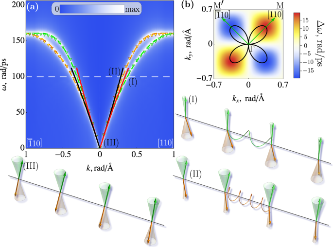
a Splitting of magnon modes in RuO2 in two orthogonal directions calculated from DFT13 (markers), atomistic spin model (dashed lines), and phenomenological model (solid lines); the blue/white colors encode spectra obtained using spin-lattice model simulations, see Supplementary Materials. (I),(II) Spin-up and spin-down magnons with large k are determined by different stiffnesses (indicated by springs), while for small momenta magnons (marked by III) the dispersion is determined by the intersublattice exchange and the difference between the two magnon branches becomes negligible. b Angular (solid line; arbitrary units) and magnitude (color code) dependence of the frequency splitting of two magnon modes.
Magnons
In a uniaxial antiferromagnet, the magnons are spin-polarized along the easy magnetic axis, and the two branches corresponding to two opposite spins are degenerate throughout the Brillouin zone15,16. In contrast, in altermagnets the anisotropy of the exchange stiffness removes the degeneracy of the spin-up and spin-down modes in a large region of the Brillouin zone, except near its center, edges, and nodal planes13.
In the context of the phenomenological theory, this effect can be understood by considering the spin-up and spin-down magnons with relatively large k, which are mostly localized at different magnetic sublattices (see Fig. 2(I),(II), and Sec. IIB of Supplementary Material). As such, their velocities are determined by a different effective stiffness, (Aiso ± Aani) for k∥[110] and ([1bar{1}0]) respectively), and their frequencies are therefore split. The splitting disappears near the Γ point (BZ center, Fig. 2(III)), where the magnons are evenly distributed between the two sublattices and the effective stiffness is mostly determined by isotropic inhomogeneous exchange Aiso and strong homogeneous intersublattice exchange. At the BZ edges, the two sublattices are equivalent, which forces the magnons at these momenta to degenerate. At these BZ edge wave vectors, the magnons can be considered as coherent oscillations with effective zero wave vector of the spins of one of the two sublattices, and as a result, the AAS plays no role. At the nodal planes, the AAS vanishes, aligning the magnetic dynamics of magnons with that of antiferromagnetic behavior. As expected from symmetry grounds, the degeneracy of the magnon modes matches the observed degeneracy in electronic band spin splitting13.
Figure 2a shows the magnon spectra of RuO2 calculated from the microscopic Hamiltonian13 (symbols), by means of the spin-lattice model simulations (color code) and the fit (solid line) by the analytical dependence
derived from the phenomenological model (see Methods). Here ωAFMR is the frequency of antiferromagnetic resonance (Strictly speaking, in the case of altermagnets, we should call it altermagnetic resonance. However, since the difference between alter- and antiferromagnetic dynamics disappears at the Γ point, we retain the traditional term antiferromagnetic resonance. (AFMR), c is the magnon velocity along the nodal planes, γ is a gyromagnetic ratio, and Ms/2 is a saturation magnetization of a sublattice. The dependence (2) is consistent with different microscopic models reported up to now17,18 in a wide range of k values, including the atomistic spin model, see Supplementary Material, Sec. I.B. The estimated values of the parameters for RuO2, obtained by fitting ab initio calculations13, are c = 35 nm/ps, γAaniMs = 0.97 rad ⋅ nm2/ps, which gives the relative splitting Δω/ω ≥ 5% starting from k ≥ 1 rad/nm. The maximum value of the splitting obtained from the atomistic model is ≤15%, which allows the contribution of the AAS to be considered as a perturbative correction.
Domain wall
Next, we compare the antiferromagnetic and altermagnetic domain walls separating domains with opposite orientations of the Néel vector. We restrict our consideration to the Bloch-type wall, where the Néel vector rotates perpendicular to the inhomogeneity axis ξ. We also ignore the Dzyaloshinskii–Morya interactions (DMI), which are allowed by symmetry and will be discussed below.
In the direction of the nodal planes the distinction between altermagnetic and antiferromagnetic states disappears, rendering domain walls with ξ parallel to the nodal plane equivalent to antiferromagnetic domain walls. In these walls, the intrasublattice exchange does not break the equivalence between sublattices. This allows the opposite orientation of the sublattice magnetization, M1(↑) and M2(↓), prescribed by the antiparallel coupling, and thus exact compensation of the magnetic moments throughout the texture, see Fig. 3a. However, in all other orientations of ξ the individual domain walls, which are localized at each of the magnetic sublattices, have different widths, ({x}_{{{{rm{dw}}}}}^{(1)}propto sqrt{{A}_{{{{rm{iso}}}}}+{A}_{{{{rm{ani}}}}}}) and ({x}_{{{{rm{dw}}}}}^{(2)}propto sqrt{{A}_{{{{rm{iso}}}}}-{A}_{{{{rm{ani}}}}}}), due to the difference in intrasublattice exchange, see Fig. 3b, resulting from the difference in the local environment, see Fig. 1i. In this case, exact compensation within the domain wall is not possible, resulting in a finite inhomogeneous total magnetization within the domain wall, see Fig. 3c.
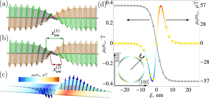
Comparison of the static AF (a) and AM (b) domain walls (see text for explanations). c Distribution of the net magnetization inside the domain wall (exaggerated). d Calculated profiles of the Néel vector (nz) and magnetization (mz) components along the easy magnetic axis for the altermagnetic domain wall (ξ∥[110]). Symbols: simulations, solid lines: analytical modeling. Inset: distribution of mz depending on the orientation of the domain wall with respect to crystallographic axes. Arrow ((overrightarrow{xi })) shows one of the directions in which the altermagnetic effect is maximal. For estimations, we take μ0Ms = 0.37 T.
One of the magnetization components is parallel to the easy magnetic axis ([001] for RuO2) and has opposite signs on opposite sides of the domain wall (Fig. 3c, d). Although the total magnetization in this direction is zero, the domain wall has a nonzero multipole moment ({mathcal{M}}_{zxi }=int{m}_{z}xi {d}^{3}{mathbf{r}}) (according to classification19) and couples with the magnetic field gradient ∂ξBz. This opens up the unique possibility of detecting and manipulating the position of the 180-domain wall with magnetic tips used in scanning probe microscopy20,21. In Fig. 4a the green line shows the calculated profiles of the Zeeman energy of the domain wall in the magnetic field generated by a spherical magnetic particle. The X coordinate corresponds to the horizontal distance between the tip and the center of the domain wall. Near the tip, the energy shows a minimum corresponding to the equilibrium position Xeq of the non-pinned domain wall. The position of the minimum shifts from the tip as the vertical distance Z between the tip and the sample surface increases (see section V of Supplementary Materials).
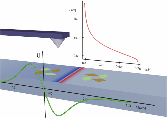
The green and gold diamonds on either side of the wall show the distribution of the altermagnetic order parameters ({U}_{xy}^{(1)}), ({U}_{xy}^{(2)}) in each domain. The color code shows the spatial distribution of mz (as in Fig. 2c). (Green line) The potential (Zeeman) energy in the magnetic field of the tip as a function of the domain wall position. The distance between the tip and the surface is 0.4 μm. For the calculations, we used the field distribution of a ferromagnetic Nd2Fe14B particle46,47 with a radius of 100 nm and magnetization μ0Ms = 2.26 T. The width of the altermagnetic domain wall is xdw = 4 nm. (Red line) The force generated at the tip by the pinned domain wall as a function of the vertical distance Z.
The horizontal force that drives the domain wall motion to the equilibrium position is highly anisotropic due to the anisotropy of the exchange stiffness and shows the same angular dependence (see Fig. 2b). This is a unique feature of altermagnetic materials, as the magnetic field does not discriminate between the 180° antiferromagnetic domains and is unable to move the 180° antiferromagnetic domain walls. We have also calculated the vertical force acting on the tip in the presence of a pinned domain wall. The magnitude of this force depends on the vertical distance and decreases from ≈1 to 0.01 pN as Z increases from 0.25 to 2 μm (see Supplementary Material for details). Notably, this range aligns with values that are experimentally accessible for detection22.
We note that the magnetic field gradient can also induce the dynamics of an antiferromagnetic domain wall by modulating the effective anisotropy23 or by coupling with small uncompensated magnetization24. However, in both cases, the effective force is proportional to the anisotropy (spin–orbit interactions) and does not depend on the orientation of the domain wall, which is in contrast to the case of altermagnetism. In these cases, the origin of the small magnetization is usually attributed to a topological Weiss-Zumino (or Berry phase) parity-breaking term (see refs. 25,26,27,28. The absolute value scales as a small ratio of the interatomic distance to the domain wall width and is often neglected in continuous models.
Moving the domain wall and the Walker breakdown
Antiferromagnets exhibit significantly higher domain wall velocities than ferromagnets because they do not undergo the Walker breakdown (see, e.g., ref. 29). In ferromagnets the Walker breakdown occurs as a consequence of domain wall deformation during motion. A similar deformation of the domain wall and the resulting modification of the magnetic dynamics was reported long ago30 for weak ferromagnets and was explained by the presence of DMI. In particular, it was shown that the presence of a small magnetization can reduce the effective velocity of the domain wall below the magnon velocity. We expect a similar deformation of the altermagnetic domain wall due to the different effective stiffnesses governing the individual domain wall widths and velocities. This effect is most pronounced in the center of the domain wall (indicated by the magenta sphere in Fig. 5a), where at v = 0, in a static state, the two sublattice magnetizations are strictly antiparallel. This exact compensation is broken at v ≠ 0 due to the motion of the sublattice domain walls with different thicknesses (Fig. 5b). The resulting canting induces internal torques that rotate M1 and M2 out of the domain wall plane. Note that this effect occurs in addition to the field/current-induced canting in other directions that induces domain wall motion. The deformation of the steady-moving domain wall is thus quantified by the out-of-plane component, δnout, of the Néel vector, shown in Fig. 5b of Supplementary Material.
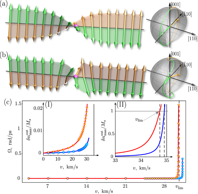
Snapshots of the static (a) and moving (b) domain wall. The motion induces canting of the sublattice magnetizations in the domain wall center (magenta spheres) due to the difference in intrasublattice stiffnesses. The canting creates intersublattice exchange torques that further rotate the magnetic moments out of the domain wall plane. The right panels show the spatial trajectories of the sublattice magnetizations in the static and moving domain wall. c Frequency Ω of oscillations between Bloch and Néel type for the steady-moving domain wall versus velocity, calculated for two values of AAS γAaniMs: 0.97 (red) and 0.2 (blue) rad ⋅ nm2/ps. The insets show the velocity dependence of the motion-induced component δnout/Ms. The moving domain wall loses stability when δnout = Ms (Walker breakdown), as shown by the arrow line. Symbols are the results of spin-lattice model simulations and solid lines are calculated from the analytical phenomenological model (see Section III of Supplementary Materials). For calculations we use xdw = 4 nm, the limiting magnon velocity in nodal directions is c = 35 km/s.
Similar to the ferromagnetic domain wall, we can estimate the limiting velocity (Walker breakdown) from the condition that the deformation reaches the possible maximum value δnout = Ms (see Fig. 5c):
Acceleration above ({v}_{lim }^{{{{rm{AM}}}}}) induces internal oscillations between the Bloch and Néel type and slows down the translational motion of the domain wall. In atomistic spin-lattice simulations, the Walker breakdown (see Fig. 5c) appears as an exponential growth of the oscillation frequency, which allows the value ({v}_{lim }) to be determined more accurately. For the detailed analysis of the domain wall dynamics below and above the Walker breakdown, we refer the reader to Sec. III of the Supplementary Materials.
The limiting velocity ({v}_{lim }^{{{{rm{AM}}}}}) is smaller than the limiting velocity c of the domain wall motion in antiferromagnets, but still much higher than the Walker velocity31({v}_{lim }^{{{{rm{FM}}}}}) in ferromagnets. This can be seen by comparing Eq. (3) with the expressions (c={v}_{lim }^{{{{rm{AFM}}}}}=gamma sqrt{{A}_{{{{rm{iso}}}}}{H}_{{{{rm{ex}}}}}/{M}_{s}}) and ({v}_{lim }^{{{{rm{FM}}}}},approx, gamma sqrt{{A}_{{{{rm{iso}}}}}{H}_{{{{rm{dip}}}}}/{M}_{s}}), where Hex is the intersublattice exchange field and Hdip is the dipolar anisotropy field in a ferromagnet. We assume that the magnetic anisotropy of a ferromagnet is of the same order of value as Hdip. Considering that the typical value of the exchange field is several orders of magnitude larger than Hdip, we get ({v}_{lim }^{{{{rm{FM}}}}},ll, {v}_{lim }^{{{{rm{AM}}}}}le c).
Discussion
The emergence of altermagnets has given us materials that amalgamate the strong spin splitting of electronic bands, characteristic of ferromagnets, with compensated magnetic order and exchange-enhanced magnetic dynamics commonly observed in antiferromagnets. In this study, we have demonstrated that the magnetic properties of altermagnets yield properties similar to those of ferromagnets and antiferromagnets, as well as some unique to altermagnets alone.
In particular, altermagnetic textures inherit the fast internal dynamics characteristic of antiferromagnets. On the other hand, unlike in antiferromagnets, altermagnetic domain walls can be controlled by inhomogeneous magnetic fields and their velocity is constrained by the Walker breakdown, akin to ferromagnets. Lastly, the anisotropic splittings of the magnon bands represent distinctive altermagnetic characteristics. In contrast to electronic spin splitting, which for low-frequency responses is experimentally accessible primarily in conductors, these magnetic effects can also occur in insulators, making them an efficient tool for the identification of altermagnetic materials.
We would like to emphasize that our model is quite general and can be applied to any of the candidates among the approximately 200 predicted d-type altermagnets. However, in this paper, we focused on RuO2 motivated by the recent experimental confirmations of its altermagnetic nature, both in the bulk10,32 and in the thin films5,33,34,35,36,37. On the other hand, we also note that bulk magnetic ordering is still being discussed; see e.g., refs. 38,39 and the more recent40 experiments. The recent theory analysis as a function of defects in ref. 41 clarifies this issue by relating the magnetic ordering in RuO2 to the presence of the defect, which are more abundant in thin films, in agreement with the experimental results.
In our discussion of altermagnetic textures, we have neglected DMI, expecting its effect to be relatively small compared to the AAS effects due to its relativistic nature. Although both DMI and AAS can induce nonzero magnetization, the AAS-induced magnetization depends on the gradients of the Néel vector and rotates with the Néel vector in spin space (See Eq. (6)). In contrast, the DMI-induced magnetization depends on the orientation of the Néel vector with respect to the crystallographic axes and can disappear for certain orientations (See Eq. (7)).
When applicable, we can incorporate within our approach the standard DMI terms in d-wave altermagnets, Dlong(m ⋅ n)nxny and Dtrans(mxny + mynx), which are responsible for the potential longitudinal42 and transverse43 weak ferromagnetism. To illustrate the difference between DMI-induced magnetization and AAS-induced magnetization, we consider a texture with the same spatial distribution but different orientations of the Néel vector and incorporate only the transverse DMI. Figure 6 compares two cases: (i) the Néel vector is along the easy axis [001]; (ii) the Néel vector is along [100]. In both cases, the direction of the inhomogeneity is along [110] (maximum AAS effect). In case (i) the spatial distribution of the DMI and AAS-induced magnetizations is the same, the only difference being the value of the effect. In both cases, the magnetizations are localized inside the domain wall. In the second case, the DMI-induced magnetization within the domains is nonzero and perpendicular to the AAS-induced magnetization within the domain wall. The AAS-induced magnetization is localized only within the domain wall, as in case (ii). From this realization, we can assume that some prior estimations of DMI (prior to the discovery of altermagnetism) were in fact, an overestimation of the DMI values, with the contributions originating from AAS not having been known and most likely dominating the magnitude of the effect.
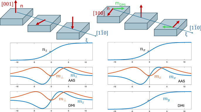
Left panel: Domain wall separating states with n∥[001] and ({{{bf{n}}}}parallel [00bar{1}]) (red arrows). Right panel: the same for n∥[100] and ({{{bf{n}}}}parallel [bar{1}00]). The graphs show the profile of the domain wall, nontrivial magnetization components induced by AAS and nontrivial magnetization components induced by DMI. In the case of the domain wall with ({{{bf{n}}}}leftVert langle 001rangle right]), the AAS- and DMI-induced magnetizations can have the same or opposite sign depending on the direction of ξ.
We have presented a phenomenological approach, supported by spin atomistic model calculations, that captures new rich dynamics of alteramagnetic textures and proposed means to control them. While other alternative approaches can be used based on the multipole series of the spin density in the real44 and in the reciprocal space19, these approaches require a conceptual modification of the equation of magnetic dynamics. Our phenomenological approach allows the description of magnetic dynamics and thermodynamics to be naturally extended to altermagnets, while retaining the Néel paradigm of magnetic sublattices.
Methods
To describe the altermagnetic textures and magnetic dynamics analytically we use a standard approach based on the Landau-Lifshitz equations for the Néel vector n and the magnetization m (see, e.g., ref. 45) :
where γ is the gyromagnetic ratio and W = ∫wdr is the magnetic free energy of an altermagnet. In a d-wave altermagnet the free energy density w is modeled as
where Ms/2 is a saturation magnetization of each of the magnetic sublattices, Hex parametrizes the intersublattice exchange that keeps the sublattices antiparallel, Aiso and Aani are the isotropic and anisotropic exchange stiffnesses, respectively, Han is the field of magnetic anisotropy. We assume uniaxial magnetic anisotropy with the easy axis along z. In Eq. (5) we have neglected the small term Aisom2. The details of the calculations are explained in Supplementary Materials, Sections II–III.
For the analytical treatment, we exclude the magnetization from Eqs. (4, 5) and express it as a function of the Néel vector and its time and space derivatives (see Sections II and III of the Supplementary Materials). In the particular case of the equilibrium texture, the magnetization has two contributions, one induced by AAS:
and one induced by DMI:
From Eqs. (6 and 7) it follows that mAAS is related to the orientation of the Néel vector and its space gradients (non-relativistic), while mDMI depends on the projections of the Néel vector on the crystallographic axes (relativistic). Note that for our particular choice of the domain wall profile (hyperbolic tangent), Eq. (6) and (7) coincide for the first case shown in Fig. 6.
The magnetic dynamics are described by the standard Landau–Lifshits equations for magnetic sublattices. The dynamical problem is considered a set of 3N1N2 ordinary differential equations with respect to 3N1N2 time-dependent components of the sublattice magnetizations. The parameters N1 and N2 define the size of the system. For the given initial conditions, the set of time evolution is integrated numerically using the Runge–Kutta method in Python. Whereas the Landau-Lifshitz equation preserves the length of the magnetic moments, we additionally renormalize the magnetic moments at each time integration step to avoid the accumulation of numerical errors. More information can be found in Section IV of Supplementary Materials.


Responses