Superior sensitive graphene fiber sensor enabled by constructing multiple nanoembossments for glucose detection

Introduction
Diabetes constitutes a prominent chronic noncommunicable disease that poses a threat to global human health. The accurate monitoring of blood glucose levels is indispensable for the prevention and treatment of diabetes1,2. Over recent decades, diverse strategies for glucose detection have been proposed, including fluorescence, electrochemistry, spectrometry, and chemiluminescence3,4. Among them, electrochemical glucose sensors have attracted widespread attention due to their exceptional sensitivity, low detection limit, low cost, and fast response5. Moreover, electrochemical sensors can be categorized as either enzyme-based or non-enzyme-based6,7,8,9. In contrast to enzyme electrochemical biosensors, non-enzyme-based biosensors offer advantages, such as higher electrical conductivity and environmental stability at a lower cost10,11,12. Therefore, non-enzymatic electrochemical biosensors hold great potential as a candidate for glucose detection13,14,15,16.
The core component of glucose sensors of this type typically consists of a nonenzymatic electrode, comprising a substrate electrode and catalyst materials17,18. The substrate electrodes of nonenzymatic glucose sensors have been gradually miniaturized, resulting in lightweight and portability19,20. Among them, fiber-shaped nonenzymatic glucose sensors (FNGSs) have gained significant attention owing to their outstanding flexibility, lightweight, high signal-to-noise ratio, and increased current density21,22. Fiber glucose sensors play a critical role in wearable technology and other fields because of their small size and convenient wearing23,24. However, the primary challenge in fabricating FNGSs lies in developing flexible fiber electrodes with superior conductivity. Traditional conducting fibers such as metal fibers25 and carbon fibers26 are limited by the low specific surface area27. Conversely, metal oxides can serve as catalyst materials (Co3O4, CuO, CuO2, ZnO, Ni (OH)2, Co(OH)2, etc.), which are extensively studied for nonenzymatic glucose sensing in alkaline environments28.
However, the commercialization of metal oxide-based nonenzymatic glucose sensors is hindered by low conductivity and catalytic activity29. Recently, there has been witnessed a remarkable upsurge in the eagerness for exploring the synergistic effect of metal–metal oxide (MMO) heterostructures to enhance electrocatalytic performance30,31. MMOs form metal-supported interfaces and strong coupling interactions, promoting catalyst stability and electron migration32,33,34,35,36. Therefore, it is of paramount importance to design a sensor with a large specific surface area and the synergistic effect of MMO heterostructures for detecting glucose in accordance with the requirements of low detection limits and high sensitivity.
In our work, a novel flexible nonenzymatic glucose sensor is shown as a GF/Au/Ni(OH)2 composite fiber. The graphene fibers (GFs) are utilized to support a high uptake of sensing molecules due to their expansive surface area and outstanding electron mobility, thereby contributing to a reduction in the detection limit37,38,39,40,41. Additionally, the implementation of Au atoms into Ni(OH)2 provides abundant attachment sites for enhanced electron migration between the working electrode and Ni(OH)2, ultimately leading to improved sensitivity and lower detection limits42. The integrated GF/Au/Ni(OH)2 electrode manifests an impressive sensitivity (1095.63 µA mM−1 cm−2) within the detection range (5 µM–2.2 mM), resulting in an ultra-low detection limit (0.294 µM). The extraordinary morphologies of nano embossments are constructed through the electrodeposition of Au and Ni(OH)2 to form MMO heterojunctions on the surface of GFs, providing multiple active sites at various angles for efficient electron migration channels. Furthermore, the GF/Au/Ni(OH)2 sensors also demonstrate excellent repeatability, anti-interference properties, and flexibility. As the flexible nonenzymatic glucose sensor, our findings offer a novel approach for constructing nano embossments on GFs to achieve superior glucose detection capabilities in the future.
Results and discussion
Figure 1a illustrates the fabrication process of GF/Au/Ni(OH)2 fiber, which involves a three-step method including microfluidic spinning, thermal annealing, and electrochemical deposition, respectively. Initially, the homogeneous GO solution is spun using microfluidic spinning and pre-reduced at 180 °C to form GOFs. Subsequently, the resultant GOFs are further reduced at a temperature of 900 °C under inert gas protection to yield GFs. Finally, GFs are converted into GF/Au/Ni(OH)2 through electrochemical deposition. X-ray photoelectron spectroscopy (XPS) analysis is carried out to identify the chemical and electronic configurations of multiple elements in the GF, GF/Au, and GF/Au/Ni(OH)2 composite fiber electrodes, as respectively, illustrated in Fig. 1b. The survey spectra unveil the presence of C1s (284 eV) and O1s (532 eV) in all three film samples, while characteristic peaks of Au4f and Ni2p are observed in GF/Au and GF/Au/Ni(OH)2, respectively (Fig. S1a, b), indicating the deposition of Au and Ni(OH)2 onto the surface of GF is successfully achieved. The electrochemical properties of the GF, GF/Au, and GF/Au/Ni(OH)2 fibers are probed through cyclic voltammetry (CV) tests in a conventional three-electrodes system. The CV curves of GF, GF/Au, and GF/Au/Ni(OH)2 under identical conditions are depicted in Fig. 1c. Upon investigation, it is ascertained that the graphene shows no redox peak within the working potential range, indicating its intrinsically electrochemically inert. Notably, an oxidation peak at 0.2 V is evident in the CV curves recorded for the GF/Au composite electrode. This observation can be attributed to the increase in the number of AuOHads sites on the GF/Au electrode when reaching 0.2 V, subsequently leading to catalytic glucose oxidation and a consequent increase in current. In the further, the GF/Au/Ni(OH)2 electrode displays a reduction peak at 0.24 V and an oxidation peak at 0.58 V, which can be ascribed to the presence of Ni (II)/Ni(III) redox couple. It is worth noting that the nanoscale Ni(OH)2 undergoes oxidation to NiOOH and reverts back to Ni(OH)2 through potential cycling in alkaline solutions. Figure S2a–c reveals the CV curves of the GF, GF/Au, and GF/Au/Ni(OH)2 fiber electrodes in 0.1 M NaOH solution with/without glucose, respectively. It is found that the GF/Au and GF/Au/Ni(OH)2 fiber electrodes have a favorable catalytic effect on glucose.

a Manufacturing process of GF/Au/Ni(OH)2 electrode. b XPS spectra of GF, GF/Au, and GF/Au/Ni(OH)2. c CV curves of GF, GF/Au, GF/Au/Ni(OH)2 composite electrode in 0.1 M NaOH solution with glucose
The surface morphology of the resultant GF, GF/Au, and GF/Au/Ni(OH)2 composite fibers are examined through scanning electron microscopy (SEM) method. Figure 2a–c depicts rough and wrinkled surface of GF with a diameter of ~130 μm, which offers a larger specific surface area for subsequent Au deposition. After the deposition of Au on the surface of GF (Fig. 2d–f), nano embossments are formed on the surface, increasing the fiber diameter to nearly 150 μm and further enhancing its specific surface area as an electrode material. Additionally, the typical images of GF/Au/Ni(OH)2 are shown in Fig. 2g–i, respectively. The Ni(OH)2 with a thickness of 2 µm is uniformly distributed on the surface of GF/Au composite fiber electrodes. The deposition of Ni(OH)2 leads to the flattening of nano embossments generated by Au, supporting multiple active sites for electron migration channels at various angles. The structural evolution diagram of the fiber electrode is clearly illustrated on the left of Fig. 2. As shown in Fig. 2j–m, the mapping conducted by energy dispersive spectrometer mapping (EDS) demonstrates the existence of C, Au, Ni, and O. The distribution of element C is confined to local gaps while Au, Ni, and O are dispersed throughout all regions, indicating successful deposition of Au and Ni (OH)2 onto the GF surface.
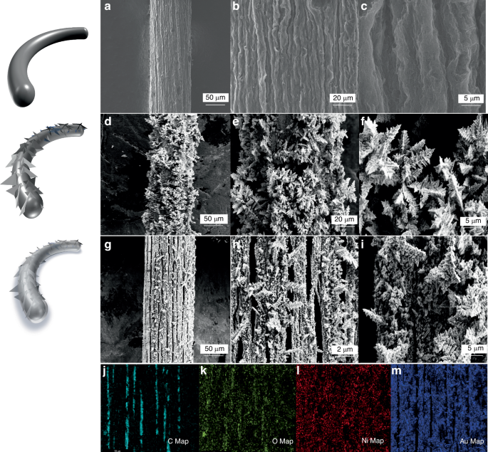
The structural morphology of the electrode surface. a–c The GF surface at different magnifications; d–f The GF/Au surface at different magnifications; g–i GF/Au/Ni(OH)2 surface at different magnification; j–m shows the EDS element mapping of GF/Au/Ni(OH)2
The mechanism of electrocatalytic oxidation of glucose on GF/Au/Ni(OH)2 composite fiber is illustrated in Fig. 3a. Hydroxide anions are chemisorbed on the Au surface, giving rise to the formation of hydrous gold oxide (AuOHads)43, which then interacts with glucose molecules to promote their oxidation into glucolactone44,45. Simultaneously, Ni(OH)2 undergoes electron transfer through Au/GF, transforming into NiO(OH) and catalyzing the diffusion of glucose onto the electrode surface for rapid oxidation into glucolactone. The specific equation for the catalytic oxidation of glucose by Au and nickel hydroxide can be expressed as follows46:
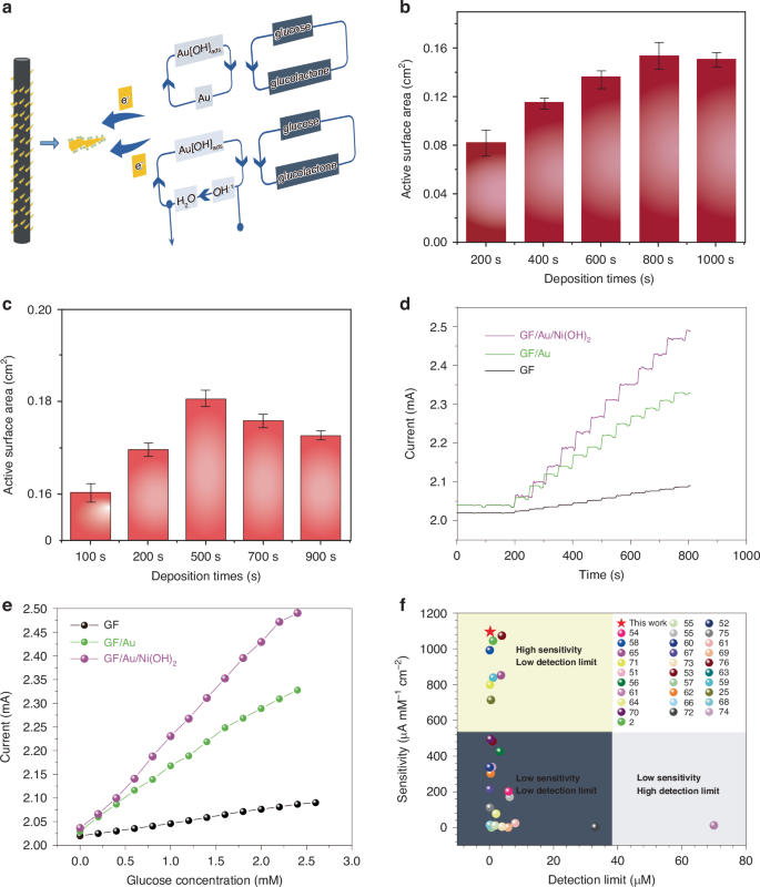
a Catalytic mechanism of GF/Au/Ni(OH)2 composite fiber electrode. b The electrochemically active surface areas of GF/Au composite fiber with different deposition times. c The electrochemical active surface areas of GF/Au/ Ni(OH)2 composite fiber with different deposition. d The I–t curves of the GF, GF/Au, GF/Au/Ni(OH)2 composite electrode with successive addition of glucose in 0.1 M NaOH solution. e The corresponding calibration curve of the GF, GF/Au, GF/Au/Ni(OH)2 composite fiber electrode. f Comparison of the analytical performance of our proposed GF/Au/Ni(OH)2 sensor with others
The ads and λ represent the chemically adsorbed species on GF/Au and the partial charge-transfer coefficient, which ranges from 0 to 147. Additionally, the MMO composed of Au and Ni(OH)2 demonstrates a synergistic effect among its individual components: Ni(OH)2 can inhibit the absorption of poisoning species on the surfaces of GF/Au, while the GF/Au can facilitate enhanced electron migration.
To compare the electrochemical active surface area of GF/Au and GF/Au/Ni(OH)2 electrodes deposited at different durations, CV curves are achieved in a solution containing Fe(CN)64−/3− (5 mM) and KCl (0.1 M) at the specific rate of (25 mV s−1) in Fig. S3a, b. The electrochemical surface area (ECSA) of GF/Au and GF/Au/Ni(OH)2 composite fibers exhibit a gradual increase with the extension of deposition time as well. It suggests that the ECSA of GF/Au and GF/Au/Ni(OH)2 electrodes can reach values of 0.164 and 0.186 cm2 (Fig. 3b, c), respectively, as determined by using the following Randles Sevcik equation48,49:
where Ip means the peak current intensity, n denotes the amounts of electrons involved in the redox process, A stands for ECSA (cm2), D means the diffusion coefficient (7.6 × 10⁻⁶ cm2 s−1), C represents the concentration of electroactive species (5 × 10⁻⁶ mol cm3), and v1/2 (V s−1) signifies the square root of scan rate.
Figure 3d displays the amperometric curves of current-time in GF, GF/Au, and GF/Au/Ni(OH)2 fibers with sequential additions of glucose. The modified fiber demonstrates a rapid amperometric response, achieving a steady-state current within <5 s upon the addition of glucose to the stirred support electrolyte (Fig. S4). The calibration curve depicted in Fig. 3e showcases the remarkable linear dependence of the GF/Au/Ni(OH)2 fiber within a glucose concentration range from 5 µM to 2.2 mM, bringing about an impressive correlation coefficient (0.9979), a sensitivity (1095.63 µA mM−1 cm−2), and a detection limit (0.294 µM), respectively.
Figure 3f illustrates the superior performance of our non-enzymatic glucose fiber sensor in contrast to similar sensors2,25,50,51,52,53,54,55,56,57,58,59,60,61,62,63,64,65,66,67,68,69,70,71,72,73,74,75,76, showcasing a detection limit ((0.294 µM) and sensitivity (1095.63 µA mM−1 cm−2). These results highlight the outstanding overall performance and accuracy of our glucose sensor in detecting glucose. Further comparison with other non-enzyme glucose sensors listed in Table S1, the core–shell structure of carbon nanotubes is utilized to form the glucose sensors. It increases the special surface area and metal-organic frameworks for enhancing the electrocatalytic performance and sensitivity. On the other hand, the sensitivity of our fabricated glucose sensor exceeds that of Ni and Ni(OH)2-based sensors by a simpler preparation process. The remarkable electrochemical properties are ascribed to the unique composition of Ni(OH)2 and Au in MMO, providing an abundance of catalysis sites for glucose oxidization, thereby optimizing detection limit, sensitivity, and linear range. Additionally, direct deposition of Ni(OH)2 and Au on GF accelerates electron migration between oxidation sites and the fiber surface, while the extraordinary conductivity and minuscule size of a single GF contribute to rapid response times
Reproducibility is a crucial characteristic of sensors for practical application. Therefore, the three fibers were meticulously fabricated and assessed through amperometric measurements in NaOH solution (0.1 M) to investigate the reproducibility of GF/Au/Ni(OH)2 fiber. The signal response from three distinct GF/Au/Ni(OH)2 fibers in Fig. 4a is illustrated as glucose (0.2 mM) is successively added, ranging from 0 µM to 2.4 mM. Figure 4b presents the trend of the mean and standard deviation (RSD) of electrodes’ responses, revealing a maximum RSD of 9.21% and thus demonstrating excellent reproducibility of GF/Au/Ni(OH)2.
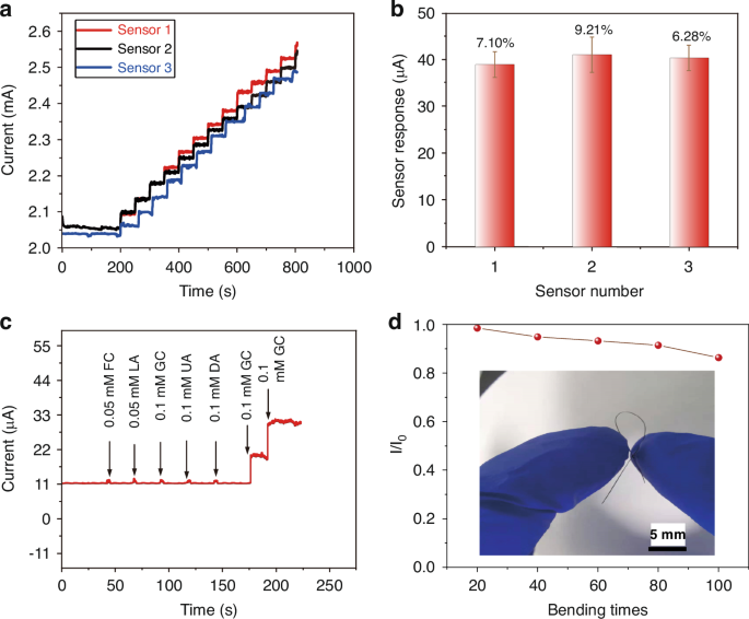
a Amperometric response of three different GF/Au/Ni(OH)2 composite fiber electrodes with successive addition of 0.2 mM glucose. b The mean and standard deviation of the responses of the three electrodes towards 0.2 mM glucose in 0.1 M NaOH. c GF/Au/Ni(OH)2 composite fiber electrode response to glucose and some common interferences, FC, LA, GC, UA DA, and GC. d Sensitivity of GF/Au/Ni (OH)2 composite fiber electrode after bending, inset shows the shape after bending
In complex physiological environments, the presence of oxidative interfering substances can influence the accuracy of glucose detection. Hence, selectivity is another key property for nonenzymatic glucose sensors in clinical applications. The amperometric response was recorded in the presence of common interfering substances in the blood to explore the selectivity of the GF/Au/Ni(OH)2 fiber. The anti-interference test involves sequentially adding 0.1 mM (glucose (GC), Galactose (GC), Uric acid (UA), and Dopamine (DA)) and 0.05 mM (d-Fructose (FC)), Lactate Acid (LA) into NaOH (0.1 M) solution, as shown in Fig. 4c, respectively. It deduces that all the tested foreign species have negligible interference to the glucose signal, indicating the outstanding selectivity of GF/Au/Ni(OH)2 electrode towards common coexisting interfering substances in the blood. The GF/Au/Ni(OH)2 fiber in our work reveals excellent electrochemical performance and flexibility under diverse deformations. As depicted in Fig. 4(d), the GF/Au/Ni(OH)2 also maintains a sensitivity of 91.4% after 80 deformation cycles, emphasizing its superior flexibility. Additionally, we conducted fiber performance following 100 bending cycles at angles ranging from 30° to 150° (30°, 60°, 90°, 120°, and 150°) in Fig. S5. When the fiber is bent at an angle below 90°, its performance remains essentially unchanged, while it can still retain 91.5% of its performance when bent within the range of 120–150°. Our findings reveal that the fibers exhibit excellent performance even under low-angle bending, with significant degradation only observed beyond 120° (Table S2). Consequently, the GF/Au/Ni(OH)2 electrode holds great potential for various applications.
The enduring stability of GF/Au/Ni(OH)2 fiber is assessed by monitoring the current response of glucose (1 mM) over a period of 14 days at room temperature and in a dry environment (Fig. S6). As depicted in Fig. 5a, although there is a slight decrease in the response current, it still maintains a robust performance (92.9%) under continuous testing for 14 days. The impact of humidity storage conditions on fiber sensor properties has been determined to be significant (Fig. S7). Stability tests carried out under dry storage conditions indicate that the fiber sensor can retain 97.9% of its performance after 14 days of storage. Consequently, the GF/Au/Ni(OH)2 electrode exhibits excellent stability during prolonged storage. On the other hand, glucose detection is not limited to a single temperature. Therefore, it is essential to test glucose sensors at various temperatures. As illustrated in Fig. 5b, the GF/Au/Ni(OH)2 fiber is subjected to glucose testing at 0, 25, 36, 40, and 90 °C, respectively. It can be deduced that the GF/Au/Ni(OH)2 fiber sensor maintains exceptional sensitivity in detecting glucose across a broad spectrum of temperatures, including both low and high extremes.
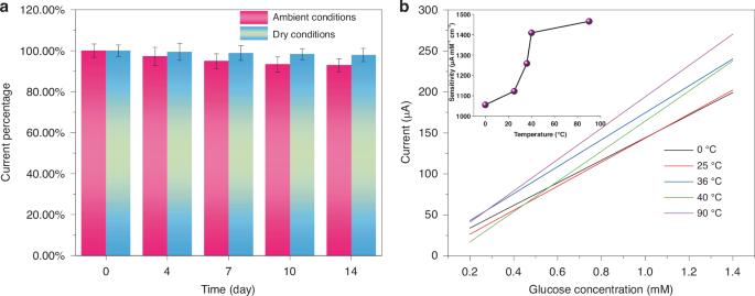
a Current response variation of 1 mM glucose on GF/Au/Ni(OH)2 electrode versus storage time. b Corresponding calibration curves of the GF/Au/Ni(OH)2 composite fiber electrode At 0, 25, 36, 40, and 90 °C, respectively
The model of the GF/Au/Ni(OH)2 sensor has been established, as depicted in Fig. 6a. The molecules of Glucose, Ni(OH)2, and Au atoms are illustrated as well, respectively. Through the utilization of modeling and mechanism analysis, we have unequivocally validated the reliability of our experimental findings regarding the properties of fiber sensors. The establishment of calculation methods utilized in developing the theoretical model can be outlined meticulously in Supporting Information. In Fig. 6, it is visually presented that the yellow cloud-like portion within the model signifies electron aggregation, while blue represents electron depletion. This serves to more intuitively illustrate the differential charge transfer process. Two-dimensional section combined with atomic coordinates is used to present the data form. Specifically, through several stages including GF adsorption, GF/Au adsorption, and GF/Au/Ni(OH)2 adsorption, a significant charge transfer phenomenon between glucose and Au-loaded Ni(OH)2 substrate has been observed in Fig. 6f and g. It expounds that GF/Au/Ni(OH)2 actively participates in glucose adsorption and enhances sensor sensitivity, leading to the consequences shown in Fig. 6h. Our combination of modeling and experimental validation has effectively unveiled the crucial role of Au-loaded Ni(OH)2 in glucose adsorption for sensor applications, offering valuable insights for optimizing sensor performance.
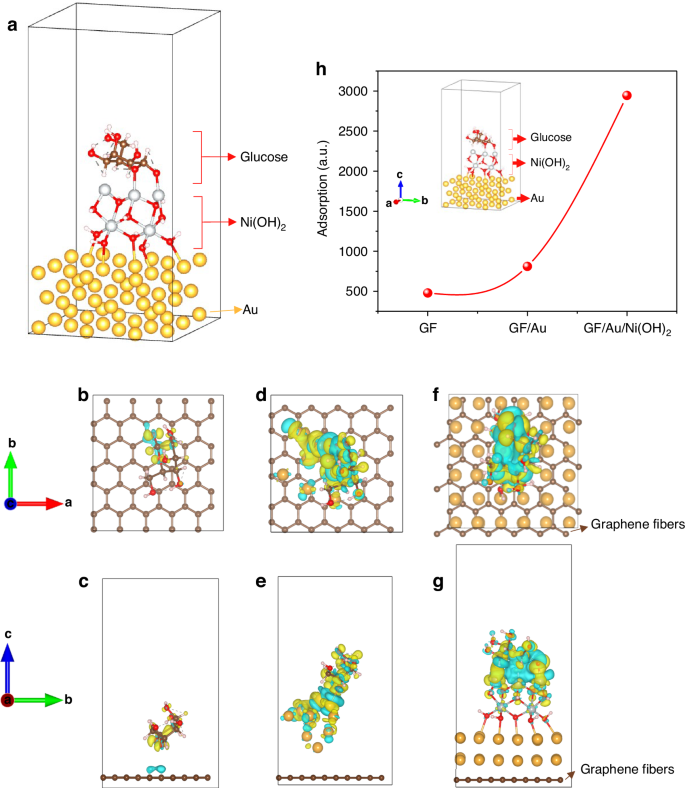
The calculated model of a GF/Au/Ni(OH)2 with glucose. b and c GF sensor with glucose, d and e GF/Au sensor with glucose, and f and g GF/Au/Ni(OH)2 with glucose, respectively. b, d, and f sensor models are in the vertical angle of view and c, e, g sensor models are in the horizontal angle of view. h The calculated adsorptions of glucose using the fiber sensors with a different structure
We employ a glucose molecule as the adsorption model. Given that calculating adsorption capacity in DFT is challenging, most studies on adsorption typically focus on the size of adsorption using a single molecule. Based on the EDD outcomes and adsorption energy, it appears that there’s a greater electron transfer between the Ni(OH)2-loaded model and glucose. Specifically, Ni in Ni(OH)2 seems to be capable of donating more electrons to the oxygen atoms in glucose, leading to higher adsorption energy. In contrast, Au and graphene surface carbon atoms exhibit less electron transfer to the oxygen in glucose. To further validate this observation, the Muliken charges77,78 were computed, which were obtained through wave function analysis with the assistance of Multiwfn software for glucose adsorption on three distinct substrates as presented in Table S4. The wave function modulus files before and after adsorption were calculated, and the Muliken charge was determined using Multiwfn to obtain the amount of electron transfer amount by subtraction. The findings reveal that the electron transfers between GF, GF/Au, GF/Au/Ni(OH)2, and glucose are 0.17e, 0.34e, and 0.42e, respectively. Consequently, we propose that the Ni(OH)2-loaded model favors glucose adsorption.
Conclusion
In summary, a novel flexible GF/Au/Ni(OH)2 composite fiber has been developed by electrochemical depositing MMO onto a graphene fiber microelectrode. This composite material combines the remarkable electrocatalytic performance of Ni(OH)2 with the prominent conductivity of Au. The resultant fiber-shaped GF/Au/Ni(OH)2 fiber electrode exhibits an impressive sensitivity of 1095.63 µA mM−1 cm−2, along with a remarkably low detection limit of 0.169 µM and a linear range spanning from 5 µM to 2.2 mM. Due to its good reproducibility and flexibility, GF/Au/Ni(OH)2 composite fiber has great promising for applications in wearable and implantable sensing.
Experimental sections
Materials and reagents
Graphene oxide (GO) was synthesized using a modified version of Hummer’s method. Chlorauric acid (AuCl4), nickel nitrate (Ni(NO3)2), and sodium hydroxide (NaOH) were obtained from Sinopharm Chemical Reagent Co., Ltd. Glucose (GC), Uric acid (UA), Dopamine (DA), D-Fructose (FC), Galactose (GC) and Lactate Acid (LA) were purchased from Sigma-Aldrich Co., LLC. All aqueous solutions were prepared using deionized (DI) water. The counter electrode (Pt electrode) and reference electrode (KCl solution saturated Ag/AgCl electrode) were purchased from Shanghai Chenhua Instrument Company.
Preparation of graphene fibers (GFs)
A simple two-step method was used to produce graphene fibers (GFs), involving microfluidic spinning and thermal annealing. Initially, a well-dispersed solution of graphene oxide (GO) at 12 mg/mL was prepared through ultrasonic treatment for 30 min. The GO solution was then injected into a polytetrafluoroethylene (PTFE) microreactor tube with an internal diameter of 2 mm using a syringe pump at a flow rate of 10 mL/h. After sealing the tube ends, the GO fibers (GOFs) were formed in the microfluidic channel under uniform vapor pressure and heated at 180 °C for 2 h in an oven. Subsequently, the preformed GOFs were pushed out from the tube with N2 flow and dried in atmosphere conditions. Then, the GOFs were subjected to high-temperature annealing in a furnace under controlled vacuum and gas flows. Prior to heating, a vacuum atmosphere of 0.1 Pa and ultrapure Argon protective flow of 200 sccm were maintained for 2 h to remove O2 and water vapor. The fibers were then annealed under argon protection at a heating rate of 2.5 °C/min up to 900 °C, followed by annealing for another 2 h before cooling to room temperature. Following thermal annealing, the GO fibers were reduced to GFs.
Preparation of the GF/Au/Ni(OH)2 fiber electrodes
The deposition of Au and Ni(OH)2 on GFs electrode was carried out by an electrochemical method. A traditional three-electrodes system was used with a Pt electrode as the counter electrode, an Ag/AgCl electrode as the reference electrode and a single GF electrode as the working electrode, as shown in Fig. 1a. The Au species were electrodeposited from electrolytes of 0.5 M AuCl4 by using the amperometric i–t curve method with the electrodeposition parameters including voltage (−0.2 V) and a series of deposition time (200, 400, 600, 800, 1000). Subsequently, the Au/GF electrode was immersed in another electrolyte solution of Ni(NO3)2 with the electrodeposition parameters including voltage (−0.4 V) and a series of deposition times (100, 300, 500, 700, 900). After deposition, the GF/Au/Ni(OH)2 electrode was carefully washed with DI water and dried at room temperature. Therefore, the GF/Au/Ni(OH)2 electrode was prepared.
Characterization
Morphology images of fibers were observed using scanning electron microscopy (SEM, Hitachi, SU-8010). Chemical identification was conducted using X-ray photoelectron spectroscopy (XPS, Thermo Fisher Escalab xi+). Raman spectrum analysis was performed with a laser Raman spectrometer (Horiba Jobin Yvon, HR800)
Electrochemical tests
The CHI 760D electrochemical workstation was used to conduct electrochemical measurements on fiber microelectrodes, utilizing a three-electrode electrochemical cell. Working electrodes included graphene fiber (GF), GF/Au, or GF/Au/Ni(OH)2 microelectrodes, while a platinum wire (0.5 mm diameter) and an Ag/AgCl (KCl, 0.1 M) electrode served as the counter and reference electrodes, respectively. Cyclic voltammetry (CV) and Amperometric i–t curve (IT) were employed to measure the microelectrodes in a 0.1 M NaOH electrolyte solution. A cyclic voltammogram was performed in a 1 mM glucose solution with a scan rate of 50 mV s−1 and a potential range of 0−+1 V. When the background current decayed to a steady state, amperometric response was performed with a 100 μl glucose solution successively added into 50 ml 0.1 M NaOH with bias voltage of +0.8 V. The applied voltage during the test was relative to the Ag/AgCl electrode. Scatter plot was drawn according to the data measured by the current–time method, and linear fitting was carried out to obtain the linear fitting curve. The sensitivity was obtained by dividing the slope of the linear fitting curve by the fiber surface area, and the detection line was obtained by dividing the slope of the linear fitting curve by three times the standard deviation. The pH experiment of the sensor was carried out in 0.1 mM (pH 13), 0.01 mM (pH 12), and 0.001 mM (pH 11) NaOH solutions for IT testing. The temperature of the storage test for the sensor are 0, 25, and 40 °C for one day, respectively. Subsequently, the amperometric response was carried out in a 1 mM glucose solution. The response current is used to determine the impact of storage temperature on the sensor. Similarly, the humidity of storage test for the sensor was conducted at 50%, 60%, 70%, and 80% levels for one day, followed by the amperometric response in a 1 mM glucose solution. The response current is used to determine the impact of storage humidity on the sensor
Responses