Symmetry-reduced topological interface for unleashing a multidirectional spin-orbit torque

Introduction
A trend of all-electric operation of spintronics devices has resulted from the development of spin-orbit torque (SOT) applications over the last decade1,2,3,4, where high-speed operations with high endurance are principally achievable for memory and logic devices5 with simple thin-film heterostructures. The development of SOT devices is linked to progress in studies on spin-to-charge conversion. In addition to its conversion efficiency, the direction of spin polarization also plays a crucial role in designing SOT device configurations6,7. Manipulation of the spin polarization direction is particularly important in solving the problem of nondeterministic nature in the switching process of perpendicular magnetization3. For the conventional spin Hall or Rashba SOT, it vanishes once the magnetization tilts down to the in-plane direction, resulting in uncontrollable final states in the absence of an applied external field. This vanishing of the SOT is caused by the symmetry of the system because rotational and mirror symmetries determine the relation between the current injection and spin polarization directions. Therefore, reduction of symmetry could be used to overcome geometric constraints in SOT applications. At an early stage of development, convoluted device engineering is used to exploit exchange interactions8,9, interlayer coupling10, structural asymmetry11,12,13, and magnetic anisotropy14. The use of noncollinear antiferromagnets (including Mn) in spin-current injection layers has been investigated, where the unconventional exchange coupling at the interface gives rise to an out-of-plane spin polarization15,16,17.
There has been considerable interest in using alternative approaches to produce unconventional SOTs by decreasing structural symmetry while maintaining the original heterostructures. A decrease in the rotational and mirror symmetries of the crystalline structure results in a warping of spin-orbit coupling (SOC) pattern in momentum space, leading to a rich variation in spin polarization that is not expected from the conventional SOT from isotropic spin Hall or Rashba effects18,19. To date, threefold symmetry has been experimentally observed in several heavy metal compounds, namely, WTe220, NbSe221, and L11-CuPt/CoPt22, where an SOT from out-of-plane spin polarization has been recently reported. The emergence of such a nontrivial torque component has enabled field-free SOT operation of heavy metal/ferromagnet (HM/FM) heterostructures in several experiments22,23,24,25. However, the typical amplitude of this SOT remains one order of magnitude smaller than that of the conventional SOT15,16,17,20, which hinders the development of SOT for various applications. Therefore, we need to design unconventional SOTs by reducing the symmetries of system, with their magnitudes reaching up to that of the conventional SOT.
In this study, we propose an alternative protocol to generate and enhance unconventional SOT based on symmetry reduction in a topological insulator (TI) material Bi2Te3. Bi2Te3 shows the spin-momentum locked electronic states on the surface, with the hexagonal warping structure due to the discrete rotational symmetry of crystal26,27,28. From such a warped spin-momentum locking structure, we may expect both the enhancement of the SOT efficiency29,30,31 and the emergence of the unconventional SOT component32,33,34. The pioneering experimental works35,36 with Bi-based chalcogenides recorded more than 100% efficiencies in their charge-to-spin conversion process, which later enabled the ultralow power SOT switching with double-digit decrease in the critical current density37. Numerous studies with TIs were conducted to improve the conversion efficiencies so far, by adjusting TI crystallinity38 or positioning the Fermi level closer to the Dirac point39. On the other hand, its capability as a platform for the unconventional SOTs, which was proposed by several theoretical works, has not been paid attention to in experiments so far.
The essence of this work is to adopt the TI not simply as an efficient source of SOT, but rather as a source of multi-directional SOT components by manipulating its unique symmetry structure. Since the effect of spin-momentum locking in the surface Dirac electrons is much stronger than the conventional Rashba SOC40,41, electron spin polarization on the TI surface is highly sensitive to symmetry reduction. Therefore, we may expect that the combination of the warping effect from the crystalline structure and the asymmetry of the sample structure can generate unconventional spin polarization of a sizeable magnitude. Here, we manipulate the (001) surface of the TI material Bi2Te3, which is originally in the threefold point group C3v42,43,44,45. We introduce an atomic-scale thickness gradient by synthesizing a wedge-shaped film to reduce the rotational and mirror symmetries of the surface. Film wedging has a marked effect on the TI surface state, resulting in further distortion in the spin-momentum locking structure. By comparing the measurements using Bi2Te3/CoFeB heterostructures without and with the film wedging, we report the emergence of multidirectional SOT arising from the film wedging. The unconventional parallel and out-of-plane spin polarizations therein reach up to 50% the conventional component orthogonal to the current flow. In particular, a spin polarization parallel to the current direction is observed in such symmetry-reduced systems, which are principally prohibited in highly symmetric crystals.
Results and discussion
Symmetry reduction protocol for C3v systems
We briefly discuss the effect of symmetry reduction on the SOT structure in magnetic heterostructures based on group theory analysis in two dimensions (2D). A spin current of a spin polarization S that is injected into a magnetic layer in response to an electric field E can exert a field-like (FL) SOT ({{boldsymbol{tau }}}_{{rm{FL}}}propto {bf{m}}times {bf{S}}) and a damping-like (DL) SOT ({{boldsymbol{tau }}}_{{rm{DL}}}propto {bf{m}}times ({bf{S}}times {bf{m}})) on the magnetization m. The possible form of the induced S is an axial vector belonging to the irreducible representation in common with the angular momentum, which can be constructed from combinations of E, m, and any other perturbations applied to the system. Symmetry reduction results in a rich variation in the SOT by decreasing the number of classes of irreducible representations4,18. Below, we consider a fixed Cartesian coordinate system (X, Y, Z) for the crystal, where the Z-axis is the rotational symmetry axis (the film normal). We extract some SOT components characteristic of each symmetry group (all possible SOT structures are listed in Supplementary Note 1: Group-theory analysis of spin-orbit torque under wedging).
We start from the largest symmetry possible at a 2D interface, the C∞v group in the continuum, which is symmetric under an arbitrary rotation ({R}_{phi }) around the Z-axis and a reflection ({sigma }_{{rm{v}}}) by arbitrary mirror planes containing the Z-axis (Fig. 1a). This situation principally applies to polycrystal and amorphous, where the crystal orientations are randomly distributed and integrated out in total. For instance, a Rashba-type SOC with in-plane spin polarization, (propto ({k}_{X}{sigma }_{Y}-{k}_{Y}{sigma }_{X})), is permitted for this symmetric structure. The linear Dirac-cone dispersion on the TI surface is the typical example in this class. The possible form of S induced solely by an in-plane E is limited to(,{{bf{S}}}_{infty {rm{v}}}propto hat{{bf{Z}}}times {bf{E}}=(-{E}_{Y},{E}_{X},0)), which is expected from the conventional spin Hall and Rashba-Edelstein effects, as shown in Fig. 1d.

Schematized structures of the interfacial bands and Fermi surface. a Isotropic heterostructures that belong to the C∞v point group. b Heterostructure with threefold rotational symmetry (C3v). c C3v heterostructure with film wedging (in the direction F), where the point group is reduced to the trivial C1 group. Schematics of the sample geometry and corresponding spin polarization ({bf{S}}) of the spin-orbit torque (SOT). d W/CoFeB heterostructure belonging to C∞v point group exhibiting only in-plane polarization ({{bf{S}}}_{infty {rm{v}}}) orthogonal to the current. e ferromagnet (FM) and topological insulator (TI) (Bi2Te3) heterostructure beonging to C3v point group permitting out-of-plane polarization ({{bf{S}}}_{3{rm{v}}}). f FM and wedged TI (Bi2Te3) heterostructure beonging to C1 point group inducing both out-of-plane polarization ({{bf{S}}}_{3{rm{v}}}) and in-plane polarization ({{bf{S}}}_{1}) parallel to the current.
The crystalline structure decreases C∞v at the interface to a discrete group. Among the discrete point groups in 2D, the C3v structure commonly appears in cubic and hexagonal crystals, including at the (001) topological interface of Bi2Te3. This point group hosts the threefold rotational symmetry R3 around the Z-axis and the reflection symmetry σv by the three mirror planes. We here fix the X– and Y-axes of the Cartesian coordinate system such that the XZ-plane coincides with one of the mirror planes of σv. The C3v structure allows a hexagonal warping for the SOC. For the 2D Dirac fermions on the TI surface, the warping effect is parametrized as (propto mathrm{Re}{left({k}_{X}+i{k}_{Y}right)}^{3}{sigma }_{Z}), producing an unconventional out-of-plane spin polarization on the Fermi surface, as shown in Fig. 1b4,18,46. This term can produce an out-of-plane spin component of the SOT, ({{bf{S}}}_{3{rm{v}}}^{Z}propto left({bf{E}}cdot {bf{m}}right)hat{{bf{Z}}}), which is allowed in C∞v but prohibited for the in-plane Rashba SOC. The C3v structure also permits in-plane components of the SOT, ({{bf{S}}}_{3{rm{v}}}propto left({E}_{X}{m}_{X}-{E}_{Y}{m}_{Y}right)hat{{bf{X}}}+left(-{E}_{X}{m}_{Y}-{E}_{Y}{m}_{X}right)hat{{bf{Y}}}), in addition to ({{boldsymbol{S}}}_{infty v}) produced by the combination of E and m. This ({{bf{S}}}_{3{rm{v}}}) makes the emergence of field-like ({{boldsymbol{tau }}}_{3{rm{m}}}={tau }_{3{rm{m}}}left({bf{m}}times {{bf{S}}}_{3{rm{v}}}right)) and damping-like ({{boldsymbol{tau }}}_{{rm{PH}}}={tau }_{{rm{PH}}}left[{bf{m}}times left({{bf{S}}}_{3{rm{v}}}times {bf{m}}right)right]) possible in C3v heterostructures, which have been classified as the “3 m torque” and the “planar Hall torque” in preceding theories, respectively19,32,33,34. These types of SOTs have been experimentally reported for the L11-CuPt/CoPt interface22.
On this C3v interface, we consider the effect of film wedging. Film wedging can be regarded as an in-plane vector-type perturbation F in the direction of the thickness gradient because it transforms under both the R3 rotations and σv reflections but does not break time-reversal symmetry. This perturbation reduces the symmetry group down to the trivial C1 group. It considerably distorts the structure of the fully spin-momentum-locked Dirac fermions on the TI surface, as shown in Fig. 1c (see Supplemental Note 1 for a detailed discussion). Combinations of E and F yield unconventional forms of the in-plane and out-of-plane components ({{bf{S}}}_{1}^{parallel }) and ({{bf{S}}}_{1}^{perp }), that are not captured in ({{bf{S}}}_{infty {rm{v}}}) and ({{bf{S}}}_{3{rm{v}}}):
where all three spin components are permitted (Fig. 1f). The out-of-plane component ({{bf{S}}}_{1}^{perp }) arises if the wedging F is designed to be perpendicular to the current injection direction E. For instance, if the current is injected in the X-direction, wedging should be introduced in the Y-direction to obtain the out-of-plane component. In this case, the in-plane component ({{bf{S}}}_{1}^{parallel }) becomes parallel to the current injection direction, ({{bf{S}}}_{1}^{parallel }propto {E}_{X}{F}_{Y}hat{{bf{X}}}). Such a component with the spin polarization along the current direction is not permitted at O(m0) in either ({{boldsymbol{S}}}_{{boldsymbol{infty }}v}) or ({{bf{S}}}_{3{rm{v}}}). These unconventional SOT components result in the extinction of the geometrically invariant point (τ = 0) during the magnetization switching process. Therefore, the symmetry engineering discussed here could be used to realize deterministic field-free switching. The F effect considered here could be applied to model any other in-plane inhomogeneity, e.g., an in-plane temperature gradient or asymmetry between electrodes, although the corresponding effects are not as controllable as those of film wedging.
Measurements of multidirectional SOT at a symmetry-reduced interface
The aforementioned protocols were demonstrated experimentally for the topological surface state of Bi2Te3. As Bi2Te3 forms a rhombohedral unit cell (Fig. 2a), its (001) surface belongs to the C3v group (Fig. 2b). Figure 2d is a schematic of an atomic-scale thickness gradient in a wedge structure that we prepared in the epitaxial heterostructure of [001]-Bi2Te3 and amorphous CoFeB (Fig. 2c). The film thickness in the heterostructure varies by (triangle t=(3pm 1)mathring{rm A}) over a channel width of 12 μm. This wedging acts as an in-plane vector perturbation F, which reduces the symmetry of the system down to the trivial C1 group, as discussed in the previous section. We used spin-torque ferromagnetic resonance (ST-FMR) to evaluate the SOT components in this heterostructure2,47. Distinct from the crystalline coordinate system (X, Y, Z), we describe the laboratory frame by the Cartesian coordinate system (x, y, z), where the x– and y-axes correspond to the directions of the current injection (j, or E) and wedging (F), respectively. To identify the effect of symmetry reduction on the SOTs, we performed the same measurements on two different samples: polycrystalline W/CoFeB (belonging to C∞v) and Bi2Te3/CoFeB with a uniform thickness (belonging to C3v).
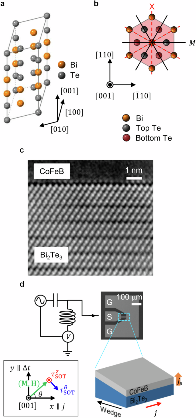
a The crystal structure of the rhombohedral Bi2Te3. b Plane view of the hexagon projected along the [001] direction, where two Bi atomic layers (orange) are sandwiched between four Te atomic layers (the top and bottom layers are shown in gray and red, respectively). For simplicity, only the atoms in the hexagonal region (shaded red) are shown. The mirror symmetry M is present for the ((bar{1}10)) plane (black solid line) but is absent for the ((110)) plane (red dashed line). c Cross-sectional high-angle annular dark-field scanning transmission electron microscope (STEM) image of the epitaxial Bi2Te3/CoFeB bilayer gazed from Bi2Te3–([100]) direction. d Schematic of the spin torque ferromagnetic resonance (ST-FMR) measurement process for heavy metal/ferromagnet (HM/FM) heterostructures. The device geometry is presented by scanning electron microscope (SEM) image of a Bi2Te3/CoFeB bilayer sample. The thickness gradient (triangle t=(3pm 1)mathring{rm A}) is set along the y-axis, orthogonal to the current direction (x-axis). An in-plane magnetic field ({mu }_{0}H) is applied to 45° from the x-axis to maximize the anisotropic magnetoresistance (AMR) projection. Both the current (|| x) and thickness gradient (|| y) are applied at the (001) plane of Bi2Te3 (the crystalline structure of the sample is detailed in Supplementary Note 3). Measurements with the uniformly thick W/CoFeB and Bi2Te3/CoFeB heterostructures are done with the same configuration.
Figure 3a–c presents the ST-FMR voltage spectra, ({V}_{{rm{ST}}-{rm{FMR}}}), recorded for the three types of prepared heterostructures, where the x-component of the magnetic field is either parallel (({mu }_{0}H > 0)) or antiparallel (({mu }_{0}H < 0)) to the current direction. The ST-FMR spectrum of the W/CoFeB heterostructure has a reciprocal structure, where inversion of the field direction flips the sign of the signal, indicating a conventional SOT structure (Fig. 3a). By contrast, the spectra of the Bi2Te3/CoFeB heterostructures exhibit clear nonreciprocity against field inversion, where an asymmetric large peak in ({V}_{{rm{ST}}-{rm{FMR}}}) for ({mu }_{0}H , > , 0) switches to a tiny dip for ({mu }_{0}H , < , 0) (Fig. 3b, c). Moreover, these nonreciprocal FMR spectra vary depending on whether there is wedging in the Bi2Te3 film. The antisymmetric component under ({mu }_{0}H , < , 0) almost vanishes at the wedge-shaped interface (see the cyan line in Fig. 3f) but remains finite in the uniformly thick heterostructure (Fig. 3e). The nonreciprocities observed here can be ascribed to the emergence of an asymmetric SOT unique to the Bi2Te3/CoFeB heterostructures. To quantify the thermal effects from the Joule heating, we also performed the ST-FMR measurements with lower power excitations. They showed the spectra with their shapes almost consistent with those in Fig. 3, which implies that the thermal effects give only quantitative differences (see Supplementary Note 6: Effects of thermal components).
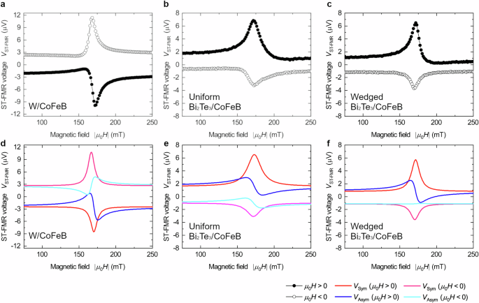
ST-FMR voltage spectra of the in-plane magnetic field ({mu }_{0}H) for (a), W (3 nm)/CoFeB (5 nm), b uniformly thick Bi2Te3 (8 nm)/CoFeB (5 nm), and c wedge-shaped Bi2Te3 (8 nm + (triangle t))/CoFeB (5 nm) heterostructures. (triangle t) denoted the film thickness variation as (triangle t=(3pm 1)mathring{rm A}). The corresponding fitted curves of individual heterostructures are plotted at (d, e, and f), respectively. The experimental data are shown as closed (({mu }_{0}H > 0)) and open (({mu }_{0}H < 0)) black symbols, and the fitted curves for ({mu }_{0}H > 0) (({mu }_{0}H < 0)) are shown in red (magenta) for the symmetric part ({V}_{{rm{Sym}}}) and blue (cyan) for the antisymmetric part ({V}_{{rm{Asym}}}). The sign of ({mu }_{0}H) is defined to be consistent with the sign of the x-component of ({mu }_{0}H).
To obtain a full picture of the SOT, we performed ST-FMR measurements with varying the direction of the in-plane magnetic field. Figure 4 shows the profiles of the symmetric and antisymmetric ST-FMR voltage components, ({V}_{{rm{Sym}}}) and ({V}_{{rm{Asym}}}), as functions of the in-plane angle (theta) of the field direction measured from the current-injection direction (x-axis), as shown in the inset of Fig. 2d. These plots are shown for the conventional W/CoFeB system in Fig. 4a, b, for the uniformly thick Bi2Te3/CoFeB system in Fig. 4c, d, and for the wedge-shaped Bi2Te3/CoFeB system in Fig. 4e, f. The conventional SOT for the C∞v point group results in simple forms48, such that ({V}_{{rm{Sym}}({rm{Asym}})}(theta )propto sin 2theta cos theta). These simple forms are shown as black dashed lines in Fig. 4a–f. For W/CoFeB, the simple forms are in excellent agreement with the observed profiles, as shown in Fig. 4a, b. However, the observed profiles of ({V}_{{rm{Sym}}({rm{Asym}})}(theta )) both the uniformly thick and wedge-shaped Bi2Te3/CoFeB heterostructures are considerably more complex and do not correspond to simple (sin 2theta cos theta) functions, as shown in Fig. 4c–f. The (sin 2theta cos theta) function is symmetric for (theta ={90}^{circ },{270}^{circ }) and antisymmetric for (theta ={0}^{circ },{180}^{circ }). By comparison, the observed profiles of ({V}_{{rm{Sym}}}) exhibit minor deviations from this behavior, and those of ({V}_{{rm{Asym}}}) are entirely different. Such discrepancies are considerably greater for the wedge-shaped samples (Fig. 4e, f) than for the uniformly thick samples (Fig. 4c, d). These differences can be attributed to the unconventional spin polarizations which are permitted by the hexagonal warping and film wedging, as has been discussed in the previous section.
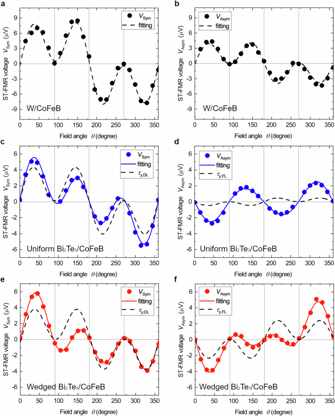
The symmetric (({V}_{{rm{Sym}}})) and antisymmetric (({V}_{{rm{Asym}}})) components of the rectified voltage are plotted as functions of the in-plane magnetic field angle (theta) measured from the current injection direction, as determined from ST-FMR measurements for (a, b), W (3 nm)/CoFeB (5 nm), (c, d), uniformly thick Bi2Te3 (8 nm)/CoFeB (5 nm) and (e, f), wedge-shaped Bi2Te3 (8 nm + (triangle t))/CoFeB (5 nm) heterostructures. The black dashed lines in (a–f) are fitted curves including only the conventional spin polarization components (({tau }_{y,{rm{DL}}({rm{FL}})})). The extended fitting results are based on Eqs. (2) and (3), including both the conventional and unconventional components of SOT (({tau }_{x,{rm{DL}}({rm{FL}})},,{tau }_{y,{rm{DL}}({rm{FL}})},{tau }_{z,{rm{DL}}({rm{FL}})})), are shown as blue (c, d) and red (e, f) solid lines.
To understand the unconventional spin polarizations from the reduced symmetries, we here decompose the observed profiles of ({V}_{{rm{Sym}}({rm{Asym}})}(theta )) into the components of SOT. Incorporating FL and DL components (left({tau }_{i,{rm{FL}}},{tau }_{i,{rm{DL}}}right)) in each spin direction (i = x, y, z) and 3 m and planar Hall components (({tau }_{3{rm{m}}},{tau }_{{rm{PH}}})), the field-angle dependence of the torque components becomes, ({{boldsymbol{tau }}}_{{rm{SOT}}}left(theta right)={tau }_{{rm{SOT}}}^{theta }left(theta right)hat{{boldsymbol{theta }}}+{tau }_{{rm{SOT}}}^{z}left(theta right)hat{{bf{z}}}), where ({tau }_{{rm{SOT}}}^{theta }left(theta right)={tau }_{x,{rm{DL}}}sin theta -{tau }_{y,{rm{DL}}}cos theta -{tau }_{z,{rm{FL}}}+{tau }_{{rm{PH}}}sin 2theta) and ({tau }_{{rm{SOT}}}^{z}left(theta right)=-{tau }_{x,{rm{FL}}}sin theta +{tau }_{y,{rm{FL}}}cos theta -{tau }_{z,{rm{DL}}}-{tau }_{3{rm{m}}}sin 2theta) (the derivation is given in Supplementary Note 2: Field-direction dependence of the ST-FMR signals). Substituting these expressions into ({V}_{{rm{Sym}}({rm{Asym}})}(theta )) yields17,49
The measured ({V}_{{rm{Sym}}left({rm{Asym}}right)}left(theta right)) can be consistently fitted by these equations. We note that ({{boldsymbol{tau }}}_{{rm{SOT}}}left(theta right)) is also affected by the back reaction from the spin pumping and the inverse Edelstein effect. Once their contributions are taken into account, the estimated value of ({tau }_{y,{rm{DL}}}) will be quantitatively shifted (see Supplementary Note 4: Contributions of spin pumping and the inverse Edelstein effect), while the estimations of the other unconventional SOT terms are left unchanged. The fitted results are shown by the solid lines in Fig. 3a–d, with the coefficients provided in Table SIII in Supplementary Note 5: Coefficients for the anisotropic SOT components. These fits produce ({tau }_{x(z),{rm{DL}}}) and ({tau }_{x(z),{rm{FL}}}) with sizable magnitudes, which are approximately 10–50% of that of ({tau }_{y,{rm{DL}}({rm{FL}})}), which implies that the unconventional SOT components are significantly induced by the symmetry reduction. The strong out-of-plane torques (|{tau }_{z,{rm{DL}}({rm{FL}})}|) comparable to (|{tau }_{y,{rm{DL}}}|) for both the uniformly thick and wedged heterostructures are attributed to the violation of the continuous rotational symmetry at the Bi2Te3/CoFeB interface. We note that the uniform thickness Bi2Te3 also shows a finite (|{tau }_{z,{rm{DL}}({rm{FL}})}|ne 0), typically at film thickness thinner than 10 nm (See Supplementary Note 3: Microstructure analysis for Bi2Te3/CoFeB heterostructures). The sputtered thicker films include more crystalline imperfections, twinning, and/or c-axis misalignments, which tend to obscure (|{tau }_{z,{rm{DL}}({rm{FL}})}|) arising from the bulk C3V structure. Our 8 nm thickness samples are designed to be thin enough to relatively avoid those obstacles.
The SOTs from the spin polarizations parallel to the current direction, ({tau }_{x,{rm{DL}}}) and ({tau }_{x,{rm{FL}}}), are only observed in the wedge-shaped sample. This type of parallel spin polarization is principally prohibited under threefold rotational and mirror symmetries, as discussed in the previous section. The emergence of these two distinct SOT components was confirmed by measurements of current-induced magnetization switching processes and the second-harmonic Hall resistivity (details are provided in Supplementary Note 7: In-plane magnetization switching process by nonreciprocal SOT in Bi2Te3/CoFeB heterostructure, Supplementary Note 8: Domain nucleation process underlying in-plane magnetization switching in Bi2Te3/CoFeB heterostructure, and Supplementary Note 9: Second-harmonic Hall measurements for Bi2Te3/CoFeB heterostructures). These results show that the symmetry reduction by atomic-scale modulation of the thickness of Bi2Te3/CoFeB produces unconventional parallel and out-of-plane spin polarizations for the SOT.
These unconventional spin polarization components lead to anisotropy in the SOT, which eliminates the invariant points satisfying ({{boldsymbol{tau }}}_{{rm{SOT}}}left(theta right)=0). To visualize these invariant points, we present vector plots of the angular profiles of the in-plane ({{boldsymbol{tau }}}_{{rm{SOT}}}^{theta }left(theta right)) and out-of-plane ({{boldsymbol{tau }}}_{{rm{SOT}}}^{z}left(theta right)) components of the SOTs in Fig. 5a, b, respectively. The SOT profile is symmetric for the W/CoFeB heterostructure (shown as black dashed arrows) but highly asymmetric for both the uniform and wedged heterostructures of Bi2Te3/CoFeB (as shown by the blue and red solid arrows, respectively). The magnitude of the in-plane component ({{boldsymbol{tau }}}_{{rm{SOT}}}^{theta }left(theta right)) for the wedged heterostructure (Fig. 5a) is almost twice as large for Hx > 0 ((-90^{circ} ,le, theta ,le, 90^{circ})) as for Hx < 0 ((90^{circ} ,le, theta ,le, 270^{circ})). The out-of-plane component ({{boldsymbol{tau }}}_{{rm{SOT}}}^{z}left(theta right)) also exhibits large anisotropy (Fig. 5b), which evidences the emergence of a sizable out-of-plane spin component induced at the microwedged topological interface. As a result of these asymmetries, the SOT magnitude (|{{boldsymbol{tau }}}_{{rm{SOT}}}left(theta right)|) also becomes anisotropic, as shown by the polar plot in Fig. 5c. To clearly show this result, (|{{boldsymbol{tau }}}_{{rm{SOT}}}left(theta right)|) for each heterostructure is rescaled by a certain factor, where the origin (|{{boldsymbol{tau }}}_{{rm{SOT}}}(theta )|=0) is represented by the inner black solid circle. Whereas the plot for the W/CoFeB heterostructure includes invariant points touching the (|{{boldsymbol{tau }}}_{{rm{SOT}}}(theta )|=0) circle at (theta ={90}^{circ }) and ({270}^{circ }), both the uniformly thick and wedge-shaped Bi2Te3/CoFeB heterostructures exhibit nonzero (left|{{boldsymbol{tau }}}_{{rm{SOT}}}(theta )right|ne 0) for any (theta), indicating the elimination of the invariant points. This behavior facilitates the deterministic switching of magnetization because the SOT remains finite anywhere during the switching process. This capability is attributed to the emergence of unconventional spin polarization components, which are the direct consequence of the symmetry reduction of the topological surface state.
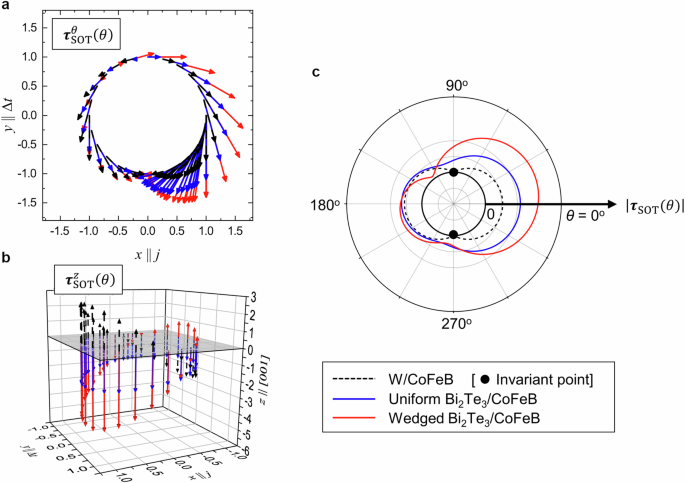
Angular profiles of (a) in-plane SOT ({{boldsymbol{tau }}}_{{rm{SOT}}}^{theta }(theta )) and b out-of-plane SOT ({{boldsymbol{tau }}}_{{rm{SOT}}}^{z}(theta )) for W/CoFeB (black dashed arrows), uniformly thick Bi2Te3/CoFeB (blue solid arrows), and wedge-shaped Bi2Te3/CoFeB heterostructures (red solid arrows). Each arrow indicates the direction of each SOT component at the angle θ. The gray plane in (b) represents ({{boldsymbol{tau }}}_{{rm{SOT}}}^{z}left(theta right)=0). c Angular profile of the SOT norm (left|{{boldsymbol{tau }}}_{{rm{SOT}}}left(theta right)right|) in polar coordinates for the three heterostructures shown in (a, b). The inner black solid circle represents (left|{{boldsymbol{tau }}}_{{rm{SOT}}}(theta )right|=0). Only the W/CoFeB heterostructure shows (left|{{boldsymbol{tau }}}_{{rm{SOT}}}(theta )right|=0) where the black dashed curve touches the inner circle (shown by the positions of the black dots), corresponding to the invariant points of the SOT.
Differences between unconventional and conventional SOTs
For the multidirectional SOT in the symmetry-reduced heterostructure, the spin-to-charge conversion efficiency6,7,49 should be extended to the multicomponent quantities ({{boldsymbol{xi }}}_{{rm{s}},{rm{DL}}}) and ({{boldsymbol{xi }}}_{{rm{s}},{rm{FL}}}) as
where (e) is the elementary charge, ({M}_{{rm{s}}}) is the saturation magnetization of the FM layer, ({t}_{{rm{FM}}}) and ({t}_{{rm{TI}}}) are the thicknesses of the FM and Bi2Te3 layers, respectively, and ({M}_{{rm{eff}}}) is the effective magnetization (see Methods). Charge-to-spin conversion occurs mainly at the 2D interface in the Bi2Te3/CoFeB heterostructures. The efficiency of the y-component of the FL SOT (the leading component arising in the C∞v group), ({xi }_{y,{rm{FL}}}), is normalized to unity. The extended conversion efficiencies from the wedged heterostructure are quantified relative to ({xi }_{y,{rm{FL}}}) as ({({xi }_{x,{rm{DL}}},{xi }_{y,{rm{DL}}},{xi }_{z,{rm{DL}}})=(-0.07pm 0.01,,0.24pm 0.02,}{-0.10pm 0.01)}) and ({({xi }_{x,{rm{FL}}},{xi }_{z,{rm{FL}}})=(-0.02pm 0.00,,0.08pm 0.01)}).
The scale of the multidirectional spin-to-charge conversion efficiency obtained above is considerably large because of the symmetry-reduced spin-momentum locking on the Dirac surface states. This result is demonstrated in Table 1, in which the conversion efficiencies ({xi }_{i}) ((i=x,y,z)) obtained for the wedged Bi2Te3/CoFeB heterostructure herein are compared with those reported in previous experimental studies on unconventional SOT components. Except for the conventional component along the y direction50,51 ((|{xi }_{y,{rm{DL}}}|,gg, 0.2)), there are considerable differences in the efficiencies of the in-plane (x) and out-of-plane (z) components. We find a notable in-plane DL torque efficiency (|{xi }_{x,{rm{DL}}}| sim 0.1), corresponding to the spin component parallel to the current direction, which has never been reported in ordinary HM/FM heterostructures due to the limitation by the rotational symmetry at the interface. Since this effect is not present in our uniform-thickness sample, we identify its origin not as sample imperfections, but solely as our symmetry reduction protocol. The highest values for this component reported to date have been achieved in structurally engineered devices, i.e., field-annealed W/CoFeB heterostructures with canted easy axes52 and ultrathin [Pt/Co] multilayers53. In contrast, our wedged Bi2Te3/CoFeB heterostructure exhibits (|{xi }_{x,{rm{DL}}}|) comparable to those champion records of structurally engineered devices, even though its structural modulation is much simple with an atomic-scale thickness gradient. In addition to the x-component, the out-of-plane DL and FL torque efficiencies, (|{xi }_{z,{rm{DL}}}| sim |{xi }_{z,{rm{FL}}}| sim 0.1), are also greater than those in previous reports using noncolinear antiferromagnets15,16,17 and structural engineering devices49,53 ((|{xi }_{z,{rm{FL}}}| sim 0.01)). We speculate that a possible origin of such an enhancement of (|{xi }_{z,{rm{DL}}({rm{FL}})}|) is the atomic-scale thickness modulation that is not exactly in the C3v structure. As given by Eq. (1), the thickness modulation, represented by the perturbation F, also yields an additional contribution to the out-of-plane spin component. Our measurement results imply that the combination of the atomic-scale thickness modulation with the strong spin-momentum locking structure unique to the Dirac surface state of a TI is a powerful tool for inducing multidirectional SOT.
Our protocol for reducing the symmetry of the topological surface state can be regarded as producing an ultimate form of the low-symmetry spin torques with sizable magnitudes, by breaking the crystalline symmetries in materials with strong SOC. This strategy has been developed over the last several years18,20, and the results of this study demonstrate an alternative route for manipulating the spin polarization in SOTs. Compared with previous engineering approaches, our approach to generate the multidirectional SOT is implemented with a rather simple design with a micro-wedge structure, which can operate with good stability and endurance in devices. Moreover, ((00l))-oriented Bi-chalcogenide thin films are formed by the weak van der Waals interactions between the adjacent the quintuple layers, and hence they can be deposited onto various substrates with different fabrication techniques54,55,56. From these features, our approach may be compatible toward the future industrial applications combined with developments of in-plane perturbation application methodologies, a pronounced wedge designing, or the glancing angle deposition (GLAD)57, etc. The concept of symmetry reduction is innovative and can be adapted without degrading the magneto-transport properties of the original devices. Thus, symmetry reduction widens the range of approaches that can be applied to forthcoming magnetic-memory technology and logic devices.
Methods
Sample preparation
The Bi2Te3 (8.0–8.3 nm)/Co20Fe60B20 (5 nm)/Ru (2 nm) multilayer was grown on a (001)-oriented sapphire Al2O3 substrate by DC magnetron sputtering. The Al2O3(001) substrate was first annealed above 1000°C for 2 hours to obtain an atomically flat surface. The substrate was then quickly moved to the sputtering chamber, and a rhombohedral Bi2Te3 layer was sputtered at 2.1 (mathring{rm A} {text{s}}^{-1}) using a Bi2Te3.8 alloy target. An atomic thickness gradient was created using a moving shutter during the sputtering process. Subsequent in situ annealing was performed at 360°C for 1 hour. It was confirmed that excess Te atoms had evaporated during the sputtering process. The formation of the stoichiometric Bi2Te3 film was confirmed by X-ray diffraction (XRD) and inductively coupled plasma‒mass spectrometry analysis. The remaining ferromagnetic CoFeB layer and Ru capping layer were sputtered at room temperature.
The Bi2Te3/CoFeB heterostructures were patterned into bars with widths of 2–40 μm, and Ta/Au electrodes for RF injection and electrodes were subsequently fabricated using electron beam lithography (EBL) and photolithography.
Film characterization
Transport in and the microstructure of the film were evaluated using XRD, resistivity measurements, atomic force microscopy, scanning electrode microscopy (SEM), and high-angle annular dark-field scanning transmission electron microscopy. The detailed results are presented in Supplementary Note 3.
The resistivity of the sputtered Bi2Te3 8-nm-thick film used for the experiments was measured as 320 ± 20 μΩ cm. The resistivity of the amorphous CoFeB in our devices exceeded 100 μΩ cm, indicating that sufficient RF current flowed through the bottom Bi2Te3 layer. The magnetic properties of the Bi2Te3/CoFeB heterostructures were estimated from FMR spectra using the Kittel model. An effective saturation magnetization ({M}_{{rm{eff}}}) of (left(120.2pm 2.4right){rm{mT}}) was determined by fitting the Kittel model to the FMR spectra. The field misalignment was estimated to be less than 0.3 mT from the symmetry of the spectra.
Measurements
The ST-FMR measurements were carried out by applying a microwave current at a fixed frequency (in the 7–15 GHz range) to the Bi2Te3/CoFeB bilayer. The lock-in technique with amplitude modulation at 1317 Hz was utilized to improve the signal sensitivity. A rotatable electromagnet was prepared and used to determine the angle-dependent torque presented in Fig. 3a–d. Magnetic fields were swept from +0.28 T to −0.27 T to drive the CoFeB through its resonance state. The transmission and reflection coefficients for the RF cables and devices were calibrated by using vector network analyzer measurements in the relevant frequency range. A microwave frequency of 15 GHz and an applied microwave power of 15 dBm were used to obtain the results shown in Figs. 2 and 3. The detected voltage ({V}_{{rm{ST}}-{rm{FMR}}}) was divided into symmetric and antisymmetric components (({V}_{{rm{Sym}}},{V}_{{rm{Asym}}})) via resonance spectral fitting as follows:
where (triangle H) denotes the peak width and ({H}_{0}) represents the resonance field.
Responses