Synergy-based robotic quadruped leveraging passivity for natural intelligence and behavioural diversity

Main
Quadruped animals demonstrate advanced, efficient locomotion strategies across diverse terrains leveraging a range of behaviours1. Illustratively, cheetahs reach over 70 mph, mountain goats manoeuvre steep, rocky landscapes, and caribou can robustly cover hundreds to thousands of miles annually in their migrations2. The development of robotic quadrupeds seeks to replicate or exceed the capabilities for applications including exploration, inspection and search and rescue3,4. The capabilities of animals stem from their unique morphological characteristics and passive biomechanical and musculoskeletal properties5. Compliance—mediated by elastic tendons and muscles—is widely recognized as a central driver of this observed physical intelligence6,7. Yet, the mainstream approach to robotic locomotion is not to replicate the physical functionality of animal systems but to approximate the biomechanics and morphology, relying on standard rigid robotic components in conjunction with serial actuators8,9. The task of implementing effective locomotion is then fully outsourced to a complex model-based10,11 or a learnt locomotion strategy12,13,14. The results achieved this way are indubitably impressive. However, they require important amounts of computation, rapid sensory-motor feedback loops, dense networks of sensors and full actuation to function properly.
A diametrically opposite approach is followed by proponents of (bipedal) passive walkers. These simplified systems utilize their structure, compliance and environmental interactions to achieve simple and energy efficient, ‘brain-less’ passive walking15,16. However, despite the early encouraging results, as of today, (semi-)passive walkers remain more of an intriguing proof-of-concept rather than fully-fledged robots17,18. Passive walkers with more than a few degrees of freedom have been only analysed in theory19 but never realized. With their limited number of degrees of freedom, even when partially actuated20, they show limited versatility and behavioural diversity, which hinders any realistic application or deployment. To overcome this, we are increasingly seeing encouraging results from approaches that exploit bioinspiration and, more specifically, physical, compliance-driven embodied intelligence21 for robotic locomotion22,23,24,25. Recent examples include the excitation of natural jumping locomotion in a cat-inspired robotic leg in ref. 26; the dragonfly-larvae-inspired compliant robot that can emulate a synchronized dual-catapult system for ballistic movements in ref. 27; a quadruped with a feline-like multijoint spine for high-speed running28; and Birdbot, an ostrich inspired robot relying upon a clutch-based mechanism yielding efficient locomotion29.
With the goal of achieving complex and versatile quasipassive gaits with full-fledged quadrupedal robots, we look to nature for inspiration. More specifically, we augment passivity and compliance with the other fundamental ingredient of animal neuro-mechanics: the hierarchical reduction of complexity through synergistic mappings30,31. Rather than directly actuating all degrees of freedom of the animal body, the central nervous system generates coordinated patterns of activation called synergies. This way, it actuates only the components of movement that are important, leaving it to the body’s physical intelligence to generate the rest of the motion. As a control principle, synergies have been applied to hands32,33,34,35, supernumerary limbs36, robotic arms37 and exoskeletons38. Arguably the most successful application of synergies has been as a principle of embodying intelligence into mechanical design. In this context, synergistic actuation has found substantial application in robotic hands39,40,41,42,43, yielding devices that can grasp and manipulate objects with minimal sensing and control requirements, while using only a few actuation sources (typically one to four). Synergies have also been successfully applied to optimize the design of a biologically inspired bat robot, to show multiple modes of bat flight44,45 and to provide a highly robust approach for humanoid robot balance control46,47. However, so far, synergistic actuation has not been applied to locomotion where there is a need for coordination between limbs, and there has been limited exploitation of how passivity can be advantageous within synergies.
In this Article, we present a passive automata with synergies (PAWS), a legged system with synergistic actuation that uses four actuators to control its 12 degrees of freedom. The four motors implement four locomotion synergies that we distil from biological data of dogs running. By combining synergy-based actuation with optimal physical compliance, this quadruped shows emergent and animal-like dynamical responses to the environment. PAWS shows fully passive locomotion gaits that are robust to environmental perturbations and present behavioural diversity. Using inverse kinematics (IKs) on motor synergies, we can also generate versatile active gaits such as sitting, jumping and running on top of the robot’s natural dynamics.
This design is fully designed by a pipeline where optimal actuation synergies and passive compliance are identified on the basis of biological quadruped motion capture data. From these, a synergy-based actuation is extracted to mimic the neuromechanical couplings seen in biological systems. We observe that this solution yields directional stiffness at the leg’s end effector, which varies across the robot’s workspace or gait advantageously. The synergistic tendon routing yields limb coupling, enabling embodied compensatory strategies and behaviours emerging purely from the system’s mechanical response. The system’s passive traits offer environmental resilience due to the bioinspired spatial stiffness and leg coupling. This provides a bioinspired approach to the design of quadrupeds, which seeks to exploit environmental interactions.
Results
By designing a robotic quadruped with motor synergies and compliance, we seek to develop a minimally actuated robot that shows robustness to disturbances and behaviour diversity. To generate this design, we find inspiration from the neuromechanical couplings displayed by biological systems. By translating animal joint motion recordings into the principle components that best describe the motions, we can extract the synergies and grouping of legs that enable replication with minimal loss of reachable poses. Following this dimensionality reduction, the joint stiffness and tendon routings for a 12-joint tendon-driven quadruped robot can be identified through optimization. By combining this design pipeline with modular hardware, we can show that by appropriately designing the impedance and postural synergies, it is possible to generate a synergy-enabled robotic quadruped that displays robust passive interaction with the environment and diverse and natural-looking active behaviours. Namely, we develop PAWS, a synergy-based quadruped that leverages only four actuators to control all 12 joints (3 per leg). We experimentally characterize the passive and actuated properties of this robot, showing the emergent robustness and rapid recovery to perturbations and the actuated capabilities of the system.
Synergy analysis from animal data
There is extensive evidence that the sensory–muscular systems of animals are organized into functional or structural couplings at different hierarchical levels, including at the neural and muscular levels 48,49,50,51. Mirroring this neuromechanical coupling in robotic systems would be hugely insightful; however, it is challenging in terms of data availability and technologies. Instead, we propose identifying motor synergies from observations of the animals’ kinematics and exploring the extent to which this can provide physically advantageous behaviours while reducing the control complexity.
To capture the forms of motion and poses seen in animals, we use an open-source dataset composed of 147,541 poses and corresponding joint angles acquired via motion capture of a dog52. Some exemplar poses and motions are illustrated in Fig. 1 and Fig. 2c. We choose to use the full dataset, as this reflects the range of possible motions and kinematics of the dog and, hence, provides a robot design that can show this diversity in behaviour. This set of postures and motions is highly redundant, as many poses show similar ratios of joint activations. This redundancy can be captured using principal component analysis (PCA), where we decompose the animals’ joint data into a number of components that seek to represent the maximum amount of variance in the animal joint data. This PCA-based dimensionality reduction was conducted by identifying the eigenvectors of the covariance matrix of the dog dataset on the recorded joint motions for different possible subsets of limbs, including all four limbs, and different two limb combinations. When analyzing the full-body, 12 joints (3 joints per leg) were considered, resulting in a 12 × 12 synergy matrix, with the columns representing the principal components. PCA was also conducted on different two-legged groupings of the four legs, to explore how different limb couplings affect the variance captured via PCA. Specifically, we focus on hind and forelimbs, right and left limbs and crossed limbs. For each of these analyses, the extracted principle components were ranked on the basis of explained variance. The results are given in Fig. 2a, where we see for all configurations, four synergies can be used to achieve upwards of ~80% across all legs.

a, PAWS together with a pictorial representation of the features contributing to the high embodied intelligence of the design. b, A schematic representation of the pipeline used to design and control PAWS. From real-world animal data, linear order-reduction methods are used to extract the synergies. These are then used as input to an optimization of the mechanical components and to find the motor activations for the synergistic system. Dog diagram in a created with BioRender.com. Credit: b, German shepherd photograph, iStockphoto; 3D dog model, Truebones Motions Animation Studios.
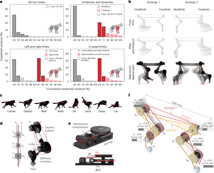
a, Eigenvectors of the PCA for different dog limb groupings ranked by explained variance. The eigenvectors highlighted show potential candidates for a physical system with a reduced actuation and, yet, a wide range of reachable behaviours. b, Top: the evolution of the first two principal components, described as synergy 1 and 2, as extracted from PCA. Middle: the evolution of the two synergies after the optimization, that is, considering the losses due to the mechanical design specifications but not considering the deployment on a real system. Bottom: the evolution shown by the real system when actuating only one of the motors. c, An example of poses from the dataset from ref. 52. d, A schematic representation of the mechanism of each leg. Each joint comprises two pulleys to guide the tendons for synergy s1 and s2 and a torsional stiffness module. e, A highlight of the torsional stiffness module with the force transmission highlighted. This is composed of two linear springs acting antagonistically on a rotational pulley. By virtue of the transmission system, a wide set of pulley radiuses can be accommodated, thus enabling a wide set of possible torsional stiffnesses achievable with the module. f, A representation of the mechanism found as a solution of the optimization, considering tendon routing, pulley sizes and stiffness at the joint level. Panel c adapted from refs. 52,67 under a Creative Commons licence CC BY-NC 4.0. Credit: a, 3D dog model, Truebones Motions Animation Studios.
Realization and transfer to a synergy-equivalent mechanism
To realize the design, the quadruped is modelled as having four legs, each with three joints. Each ‘half-dog’ (that is, one forelimb and hindlimb) has two motors connected via a pulley to the two tendons that route each synergy. Each tendon is guided by a set of pulleys left free to rotate around the centre of rotation of each joint (Fig. 2d). Each joint is connected to the subsequent link through a torsional spring, encapsulated in the mechanism depicted in Fig. 2e. The robot design is composed of modular parts, in which the radius of the pulleys guiding each tendon, the direction of the tendon routing and the torsional stiffness for each joint can be fully parametrized and rapidly customized. Given the selected number and distribution of the synergies, an optimization process reported in the ‘Synergy formulation and optimization method’ section is performed to generate the tendon routing, pulley sizes and joint stiffness to best achieve the identified synergies. The cost function for the optimization is designed so to penalize differences in joint activations between the synergy base and the resulting motion of the mechanism. The evolution of the joints in the real system is formalized as the static equilibrium between the torsional springs embedded at the joint level and the tension exerted by the multiarticular tendons. Therefore, by varying tendon routing, pulley sizes and joint stiffness, it is possible to achieve different motions as a function of the tendon activation of the motors. A schematic representation of the resulting optimized robot, topology and synergy routing is shown in Fig. 2f. The design has a high stiffness in its front foot and rear hip and a lowest stiffness in the rear foot and hip showing an inverse distribution of stiffness between the fore- and hindlimbs.
Despite the limited number of actuators in the half-dog, the two synergies can be blended to achieve a wide workspace, as shown in Supplementary Video 1. The extent of this workspace was visualized by systematically blending the synergies with varying ratios and recording the pose of the two feet with motion capture (Supplementary Fig. 8b).
Gait IKs
By performing the IK within the workspace of the robot, it is possible to generate motor activation for each of the synergies that generate different bioinspired animal gaits. Starting from motion capture of the animal, the target gait motion is defined by their front and back end-effector (paw) motion for a period or sequence of this gait. This motion is scaled to the size of the robot, and IK is performed in synergy space. Three key examples of different gait patterns are shown in Fig. 3a for walking, sitting and running, with the target animal-inspired gait, and obtained from IK using only two synergies. Despite the reduced actuation set, the robot can track the different gaits.

a, Examples of behaviours that are possible to track with the reduced motor set. In particular, in grey, the trajectories recorded on real animals are reported, while in red it is possible to observe the tracking achievable with the robotic system. b, Evolution of each of the six joints during a walking gait. In grey, the evolution of the joint on real-world animal data is reported, with a confidence level based on the variation over multiple cycles. Shown in red is the joint evolution for the robotic system, generated by solving the IK problem on the synergy base. As demonstrated by the matching, by solving the IK problem on the synergy subspace, we force the redundant kinematic of the system to reach Cartesian positions with biologically significant poses. This serves as an analysis of the biological equivalence in gait that arises from the use of synergies when performing IK.
The IK considers only the Cartesian position of the end of the two legs; however, to fully leverage the synergy and IK based upon the bioinspired gait, the means and route through which this gait is achieved are important. This can be measured by comparing the evolution of the six joint angles between the animal data and that of the robot, as given in Fig. 3b for the walking gait. Despite the IK considering only the end effector and the robot having some differences in morphology, the evolution of the robot’s joint angles shows clear similarities to the animal data. This correspondence in Cartesian and joint space between animal and robot demonstrates how the synergy basis assists in implicitly capturing the gait and the evolution by which the redundant leg system reaches a Cartesian position.
Passive properties
In addition to being able to achieve bioinspired gaits and motions, by optimizing the design using animal motion, the design captures advantageous passive properties, namely, a robustness to external perturbations and a passive gait pattern. While direct actuation of the robot is necessary for functionality and this can augment the passive response by embedding advantageous properties at the hardware level, this can offload the computation required for such tasks to the body. The passive properties of the robot can be experimentally evaluated by placing the robot on a treadmill without connecting the motors to the tendons, counterbalancing the robot with a four-bar linkage such that it stabilized and observing the response to different treadmill speeds or various external disturbances.
When the four-legged passive robot is placed on the moving treadmill, there is an emergent periodic galloping-like gait that shows coordination between the fore- and hindlimbs. This passive response is shown in Fig. 4a, top, showing the leg motion and rise and fall of the robot. When compared with the running motion of a dog (Fig. 4a, bottom), we see similarities in the motion of the robot, with the passive properties mirroring a typical running gait.
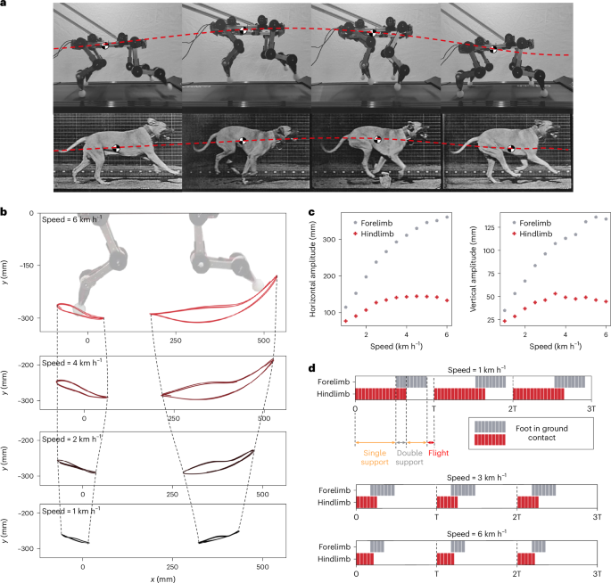
a, Emergent evolution of the robotic system when excited by the interaction with the treadmill. Due to the interjoint mechanical couplings and the compliant interaction, we can see some visual similarities to gait pattern of the robot (top) and the real (bottom) dog. b, The trajectories emergent of the paws corresponding to different levels of energy provided by the environment, parameterized with the speed of the treadmill. The repetitiveness of the trajectories proves the stability of the locomotion pattern over a variety of environmental conditions. In the passive experiment, the robot still has the synergy-based tendon routings such that the fore- and hindlimbs are connected, but the synergies are not actuated via the motors, instead the energy is input in the system by any forces applied by the treadmill to the robot’s limbs, which, in turn, can lead to tendon activation. c, An analysis of the emerging locomotion pattern. Both the horizontal and vertical variations of the amplitude are as a function of the speed. d, An analysis of the footfall pattern as a function of the period. Notably, different levels of excitation lead to different, stable, locomotion strategies, defined by varying levels of stance and flight time.
For the passive properties to provide advantageous robustness and also enable a variety of motions, the passive response must vary for different external inputs to the system. This can be simulated by varying the speed of the treadmill and observing the resultant gait. By tracking the ‘paws’ of the robot via feature tracking of videos, the foot trajectories and, hence, the footfall of the emergent gait can be recorded. The resultant trajectories are shown in Fig. 4b for an increase in treadmill speed from 1 km h−1 to 6 km h−1, with the trajectory given relative to the top of the robot. The trajectories show a similar form; however, the amplitude of motion increases with treadmill speed and, in particular, for the forelimb. This shows similarities to biological quadrupeds running with increasing speed, with the forelimb moving further forward to achieve a larger stroke to sustain the increase in speed. Figure 4c reports the amplitude of the gait with increasing treadmill speed for the fore- and hindlimb, showing an increase in forelimb amplitude, whereas the hindlimb increases until reaching a plateau at approximately 4 km h−1. Unlike the passive dynamic walker, which has rather a fixed gait in response to stimuli, the introduction of synergistic coupling and directional stiffness provides diversity in the response to stimuli, providing scaffolding for more complex actuated behaviours.
The gait can also be analysed in terms of the footfall, to identify the progression between single support (single foot contact), double support (double foot contact) and flight period that occurs. By analyzing the trajectory and contact with the treadmill, the contact time for the fore- and hindlimbs can be determined for a period of passive motion. This footfall analysis is shown in Fig. 4d for different treadmill speeds. The progression from a single support to double and then flight periods matches the progression seen in dog gaits. Furthermore, with increasing treadmill speed we see a notable reduction in the single and double support periods, with much of the gait period forming the flight component of the stance. This shows that for varying treadmill speeds we see the emergence of different behavioural patterns and gait forms, where the synergies and design of the body determine this motion. Moreover, the emergent contact profiles match locomotion strategies in biological quadrupeds, which show increasingly shorter stance phases for faster locomotion strategies53,54.
Response to perturbations
A second property observed in animals where passivity contributes is robustness to perturbation. As perturbation can occur rapidly, having a response that is not reliant on the brain provides robustness and a speed of response that enables behaviours to resume rapidly. We can explore the robust properties of the system by passively exciting the robot using the treadmill and applying various forms of disturbance and perturbation. Using the setup shown in Fig. 5a, further discussed in the ‘Animal motion analysis’ section, various disturbances can be applied to the legs or body of the robot (Fig. 5b).

a, An experimental platform used to capture the performance of the system for both the half- and full-body versions. A four-bar linkage connects the robot to a fixed support, while the treadmill excites the system. A weight of 1.5 and 3 kg is applied at the end of the four-bar linkage for the half- and full-body versions, respectively, to partially compensate gravitational forces. b, A set of exemplary perturbations applied to the system, which demonstrates passive and coordinated response, as in Supplementary Video 3. This emergent robust and animal-like passive response is highly dependent on the correct deployment of the synergy theory on the mechanical design. Indeed, a change in routing direction in any of the joints leads to immediate failure of the passive gait pattern, as shown in Supplementary Videos 7 and 8. c, The trajectories of fore- and hindfoot when perturbed at the ankle level or at the centre of the body. After a transient, highlighted in red, the robot returns to the dynamic passive walking cycle. The robot is completely passive, that is, no motors are mounted on the robot, and the full system is powered by the contact between the treadmill and the paws. d, On the left, a timestamp of the dynamic response of the system to obstacles of different heights placed on the treadmill. On the right, the success rate as a function of the obstacle height, recorded on 30 experiments per obstacle.
To quantitatively analyse the response of the passive robot to disturbances, the half-dog robot is placed on the treadmill at a speed of 4 km h−1 and perturbations are applied to the forelimb, body and hindlimb (Fig. 5c). The trajectory of both feet is recorded before perturbation, during and after. For all disturbances, the gait rapidly returns to the limit cycle behaviour observed before perturbation. For the forelimb perturbation, this is particularly evident, with the external influence causing a large offset of the forelimb and a small coupled response in the hindlimb. By the next period, the steady-state gait trajectory is observed with minimal differences. Similarly, for the body perturbation that causes a perturbation in both legs, there is a high robustness, with a rapid return to the previous gait cycle. Finally, the response of the hindlimb, which is stiffer at the hip level and, hence, requires more energy to be displaced, is slower, taking approximately four gait cycles to return to steady-state behaviour, as more energy is stored in the system.
In addition to the robustness to external perturbations, the ability to overcome obstacles within the environment is widely seen in quadrupedal animals. By placing obstacles of varying heights on the treadmill at random intervals the response to these obstacles and the success rate can be measured. Figure 5d, top, shows a timelapse of the response of the dog to disturbances to the forelimb, and Fig. 5d, bottom, disturbances to the hindlimb. In both cases, the passivity and compliance in the system allow the robot to robustly overcome the obstacles in a manner that appears bioinspired. The mean success rate across 30 trials was measured for obstacles of different heights, and we see that lower obstacles (20 mm) can be overcome purely by leveraging the passivity and compliance of the system. With the increase in height, the success rate drops, with only 65% of 60 mm obstacles being successfully overcome. These objects correspond to 20% of the robot’s height and suggest that, as with animals, for obstacles of a certain height, the response requires active control in addition to passivity and compliance.
Behaviour diversity of the full quadruped
By combining the passive properties obtained from the optimized design and the synergy routing, with direct actuation, we leverage the passive properties while expanding the behavioural diversity of the system. This can enable a deployable, passive, synergy-enabled quadruped, which can show different gaits with only four independently controlled actuators.
The robot can be actuated using motor activations generated via IK for different motions. In Fig. 6a, it is possible to see the tracking of an actuated walking gait trajectory performed on the treadmill setup and how it compares to the purely passive gait at the same speed. Notably, by virtue of the actuation, the amplitude of the gait can be increased in both horizontal and vertical directions. When comparing actuated and passive gaits in the robustness to obstacles experiment seen in Fig. 5d, the actuated gait allows higher obstacles to be overcome.
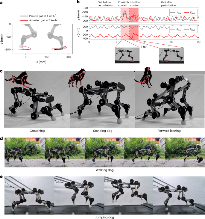
a, A comparison between the active and passive trajectories of the half-dog, shown relative to the ground, both moving at a treadmill speed of 1 km h−1. b, The gait pattern changes over time when encountering an obstacle, showing how the legs’ coupling causes perturbations to be reflected in the opposite leg, where x and y fore and hind refer to the planar Cartesian coordinates of the fore and hind paws. c, The robotic system transitioning between quasistatic poses, such as crouching, standing and forward leaning, thus demonstrating to support its self-weight. d, PAWS, supported by tendons for self-stability, is actuated with the signals extracted with the IK to perform a walking pattern. e, Motor activation is triggered on top of passive dynamic walking to start a jump, followed by a robust passive recovery and run.
Notably, during actuated gaits, the passive properties of disturbance rejection are preserved as a result of underactuation and distributed compliance. In Fig. 6b, the legs are tracked in Cartesian space, before, during and after perturbation due to the contact with a 3 kg obstacle. It is possible to observe that, before the perturbation, the actuation enforces a periodic and stable walking gait. Yet the passivity-based robustness is still observable. The gait, perturbed by the contact with an obstacle on the fore- and hindlimb, respectively, rapidly and robustly returns to the previous actuated pattern.
To further demonstrate the versatility of synergistic actuation, four varying gaits have been selected from the animal dataset, and synergy activations are extracted to best track the trajectories of these. Figure 6c shows crouching, standing and forward-leaning motions on the fully free-standing PAWS robot. As shown by the relative dog poses, these configurations closely mirror the bioinspired poses from which they are obtained. Moreover, the experiment demonstrates the ability of the compliant body to fully support its weight, while remaining compliant to mechanical perturbations.
In Fig. 6d, it can be observed that the robot, guided by a tendon, exhibits an actuated walking gait, where the activations of the walking synergies shown in Fig. 3a are utilized in an out-of-phase manner between each half-dog. Ultimately, passive and active behaviours can be combined. For example, in Fig. 6e, from the passive galloping behaviour that emerges from the interaction with the treadmill, a jumping gait can be triggered by actuating the motors at a high frequency during the onset of the hindlimb contact.
This variety of gaits, encompassing crouching, standing and forward-leaning motions, as well as the ability to transition from passive galloping to jumping and actuated walking, exemplifies the wide spectrum of behaviours attainable with minimal actuation.
Discussion
Quadrapedal locomotion is a topic that has long engaged and fascinated researchers in biomechanics, robotics, neuroscience and learning communities. Legged robot designers often disregard the postural couplings shown by biological animals, opting for full actuation and complex control schemes. However, animals’ agile and robust performance suggests that robot designs could greatly benefit from a comprehensive understanding of complex mechanisms and strategically designed compliance seen in the biomechanics of animals. This has the potential to simplify the required control, by offloading some computation to the body, and it is particularly relevant for achieving control decisions that must be made rapidly or even instantaneously. However, implementing such mechanisms remains a central challenge to enable leg control that is simple, fast and cost-effective and that can begin to match the biological counterpart.
The approach we propose focuses on maximizing the behaviours and properties that can be performed by the embodied form of the robot. Specifically, we show that by integrating adaptive synergies, not only can we reduce the number of actuators required to control the robotic structure but also we can enhance the adaptability and robustness of interactions between the robot and the environment. By developing PAWS, a synergy-based free-standing quadruped, we highlight the potential of this approach and how it an be used to underpin the design of future quadrupeds.
The proposed robotic design approach facilitates the design of robotic structures that demonstrate bioinspired mechanical recovery strategies, offering particular benefits for navigating uneven, unpredictable or soft terrains. By utilizing the biologically relevant poses, the joint stiffness can be designed to reflect the interaction impedance used by animals when interacting with the environment. Further research is required to fully understand how variable stiffness can be translated to robotic systems to enable body-driven animal locomotion.
Methods
Animal motion analysis
The openly available dataset from which we extract the synergies is 30 min of motion capture footage of a dog recorded on flat terrain52. The data itself are unstructured and contains various canine gaits, including walk, pace, trot and canter, as well as sitting, standing, lying, jumping and idling. To facilitate analysis and interpretation, a skeleton model composed of 27 bones and 81 degrees of freedom was fitted to the captured data52. This skeleton model allows us to analyse the kinematics of the dog thoroughly.
The angles of the 12 joints in the dog’s limbs were extracted by analyzing skeleton motion files at different time frames. To do this, the joints’ markers were connected with segments, and the relative angles between each consecutive segment were obtained. Specifically, the evolutions of the shoulder, elbow and carpal (wrist) joints were extracted for the forelimbs, while the evolutions of the hip, stifle (knee) and tarsal (ankle) joints were extracted for the hindlimbs. This analysis covered a total of 147,541 video frames.
To obtain the paw trajectories in two dimensions, the position of the distal marker linked to the front and back paws is tracked over time in the sagittal plane and transformed relative to the marker tracking the dog’s base at the sacrum.
Synergy formulation and optimization method
A general animal or robotic kinematic structure can be defined by a vector of n joint angles, (mathbf{q}in {{mathbb{R}}}^{n}). A postural synergy base is an orthogonal base of the joint space55, described by a matrix (Sin {{mathbb{R}}}^{ntimes n}). This allows the structure’s configuration to be described by the vector (mathbf{sigma} in {{mathbb{R}}}^{n}), as q = Sσ. Each column of S represents a coordinated motion in joint space, also referred to as postural synergy. The ith element of σ represents the amount of movement of the structure along the ith synergy.
Several studies in the literature, especially focused on humans, have shown that biological movements can usually be accurately described with a remarkably low dimensional synergy subspace. More precisely, for the case of k < < n, we can define S as
where S(k) is the first k columns of S, σ(1:k) is the first k elements of σ and ≃ is defined in the statistical sense. In other words, all movements observed can be explained to a certain degree by combining k fundamental motions rather than n.
We show in the ‘Synergy analysis from animal data section’ that a synergistic behaviour also underpins the legs of a dog while running. In our case, we selected two synergies (k = 2), as discussed in the ‘Realization and transfer to a synergy-equivalent mechanism’ section; however, the following analysis remains general. We refer to ref. 56 for an analysis of the trade-off between the number of synergies and the diversity of behaviour reproducible with these.
In the following, we propose a method to automatically translate the synergies extracted from data into design specifications for an artificial system. We refer to underactuated structures in the general form introduced (for robotic hands) in ref. 57, with the generalization of the tendon routing included in ref. 40. This class of underactuation strategies58 involves k motors whose rotation angles are the σ(1:k) in equation (1). Each motor is connected to a tendon that goes through the whole kinematic structure, revolving around joint-level pulleys. We collect the radii of these pulleys in a matrix (Rin {{mathbb{R}}}^{ntimes k}), and we call Ri,j the radius of the pulley corresponding to the ith joint and the jth tendon. A linear torsional spring is placed parallel to each joint. The stiffness of the spring acting on the ith joint is ({kappa }_{i}in {mathbb{R}}), and the complete vector is (mathbf{kappa} in {{mathbb{R}}}^{n}). Figure 2c shows an example of such a mechanism. We propose here to automatically identify and set the optimal stiffnesses k, pulley sizes R and tendon routing ρ for a desired synergy ({hat{S}}^{(1:k)}) by solving the following nonlinear mixed-integer optimization problem:
The minimum and maximum allowed stiffnesses are κ−, κ+ and the minimum and maximum allowed radii of the pulleys are r− and r+. Here, ρi,j defines if the tendon is routed counterclockwise, not routed or routed clockwise around the pulley Ri,j. The symbol ∘ is the Hadamard product of the two matrices, also called the element-wise product. The symbol ({(cdot )}_{E}^{+}) refers to the Moore–Penrose pseudoinverse of the argument weighted through the matrix E. Finally, ∣∣⋅∣∣F is the Frobenious norm of the argument, so the cost function is the squared Frobenious distance between the desired synergy matrix ({hat{S}}^{(1:{rm{k}})}) and ({(Rcirc rho )}_{{rm{diag}}{kappa }}^{+}).
In the following, we show that ({(Rcirc rho )}_{{rm{diag}}{kappa }}^{+}) is the synergy matrix of the mechanical system with physical characteristics κ, R and ρ, thus justifying the definition of the cost function in equation (2). These derivations are akin to the ones proposed for robotic hands in refs. 40,57.
Call the tendon positions (xin {{mathbb{R}}}^{k}), then, by using kinetostatic duality, the torque vector τ at the joints and the tendon tension vector τM are related by τ = (R∘ρ)⊤τM. By including a linear elastic force arising from the springs at the joints (diag{κ}q), the equilibrium of the joint torques is achieved. If no external forces are considered, the static solution can be written as (R∘ρ)⊤τM = diag{κ}q. By solving for q, it yields to (q={rm{diag}}{{kappa }}^{-1}{R}^{top }{((Rcirc rho ){rm{diag}}{{kappa }}^{-1}{(Rcirc rho )}^{top })}^{-1}x). Finally, recalling the definition of weighted Moore–Penrose pseudoinverse and that the motor state is our synergy reference variable (that is, x = σ), yields the desired relation (S={(Rcirc rho )}_{{rm{diag}}{kappa }}^{+}).
Each synergy is actuated in planar motion by an actuator (Dynamixel XL430-W250-T) fixed to the body of the robot, pulling on a tendon that is attached at the very tip of the limb on an axle (see Fig. 1a for a picture of the setup). Hence, for two synergies, two motors are used, one on each side of the leg, leading to a total of four motors for the full system.
A set of independently actuated tendons, guided by pulleys, running along joints with the stiffness specified in E, is proposed to translate animal movement to a robotic structure, such as in Supplementary Fig. 8.
Selection of synergies and robot prototype
When all four limbs are considered, four synergies can provide ~88% explained variance, as shown in Fig. 2. While this is comparatively very high, it is accompanied by the realization challenges of having shared tendons across four legs. Separating fore- and hindlimbs leads to an undesirable disparity in the explained variance between the two limbs, with a lower performance for the forelimbs. Having synergies for left and right limbs or the crossed limbs provides a similar overall performance ~81%, we select to use the synergies with separate left and right limbs, as this simplifies the mechanical design and implementation. With this selected synergy and limb groups, an upper bound of the achievable variance of the motion set can be identified as 79% when using only four actuators, that is, integrating two synergies per half-body. We perform an analysis of how the resulting PCA and synergies might change if different kinematic data from different gait types are used (Supplementary Information).
Therefore, PAWS is composed of two half-bodies, making it symmetric with respect to the sagittal plane. The robot’s design parameters are provided in Supplementary Fig. 8a. The joints, pulleys of the transmission system and the central body are three-dimensional (3D) printed from polylactic acid (PLA) on a 3D printer (Prusa Mk-3). Each half-body is driven by two actuated tendons, each corresponding to a synergy. Two motors (Dynamixel XL430-W250-T) actuate each synergy. The robot’s rigid links are connected via ball bearings to a central shaft providing robustness and are also connected via screws to each modular torsional spring module.
Modular design set
To translate synergies into optimized design specifications we create a modular design that has the following components:
-
Links, which serve as the foundation of the robotic structure and feature a tunable rest position that can be adjusted in 45∘ increments. They are machined in aluminium using computer numerical control system (CNC) technology for precise and accurate fabrication. The lengths of the links are parameterized so to reflect the animal skeleton and its kinematics.
-
Torsional stiffness joint modules composed of two antagonistic linear springs, a tray and a pulley, which are responsible for providing compliance to the robotic structure as specified by the optimal E matrix. These modules feature tunable torsional stiffness that can be adjusted linearly from 325 to 1,092 N mm rad−1 by increasing the radius r of the stiffness pulley, according to equation (3) presented in the ‘Revolute joint design’ section.
-
Tendons, which are responsible for the control of the robotic structure and transmit the force from the motors to the joints. The tendons used are metal with a diameter of 0.4 mm.
-
Guiding pulleys, which are responsible for controlling the motion ratios of the robotic structure at the joints.
-
Feet, which provide floor contact and stability. The balls are cast in Dragon Skin 20 silicon to create compliant and high-friction feet.
Ball bearings are used in all rotational contacts, to reduce friction and, thus, increase the efficiency and performance of the robotic structure. Aluminium rods are used at each joint along with 3D-printed mechanical stoppers to hold the modules together. Figure 2c shows a render of the assembled view of a three-jointed leg structure using the aforementioned modules. The components are carefully designed and tested to work together in a synergistic manner, resulting in an optimized and highly efficient robotic structure that can be easily resized and customized for a wide range of animal structures.
Revolute joint design
The need for both joint rotation and tunable torsional stiffness in a revolute joint design prompted the creation of a stiffness module incorporating linear springs. The mechanism employs a central stiffness pulley that facilitates rotational motion, with wires attached on two opposite ends. Simultaneously, two linear springs act antagonistically to provide stiffness in both directions as illustrated in Fig. 2d. This design enables a large range of possible stiffnesses by using a pulley reduction with a ratio of 2:1 to maximize the range of stiffness achievable within the linear region of the spring. The modules can be stacked onto the joint and cause them to have a torsional stiffness resulting from the linear stiffness in the modules.
The torsional stiffness kθ can be calculated by computing the moment at the joint per angle of rotation when the two springs are acting (see Fig. 2d for free-body diagrams)
With this result, the design enables quadratic scaling of stiffness through the r2 term. Owing to the quadratic relation, the stiffness module is able to vary the stiffness across a wide range with small changes in the pulley radius. This feature, combined with the 2:1 pulley system enables a wide range of achievable stiffnesses within the linear region of the deformation of the springs.
Sim2Real transfer
Given the identified design of the robot from the optimization process, the matching to ideal synergies obtained from the animal data in both simulation and on the real-world hardware can be evaluated. In Fig. 2b and Supplementary Video 1, the simulated motion path enabled by the two independent synergies is shown for that directly from PCA (top), a simulation after the optimization process (centre) and finally deployed in the real world on the robotic hardware (bottom). Here, each synergy is activated, and the ‘foot’ pose of the robot is captured via simulation or video tracking. It can be seen that synergy 1 provides predominantly hindlimb motion, whereas synergy 2 provides mostly forelimb motion; however, there is some coupling between them. The optimization step introduces marginal error in comparison to the PCA results with a loss in joint couplings of 8% and 4% for the first and second synergy, respectively. There is also some additional coupling between the legs. When deploying the structure to the real world there is a close similarity in the expected motion path; however, the fore- and hindlimb coupling is further extenuated for both synergies. This is most probably due to the optimization constraint of having all the joints coupled. This gap can be quantitatively assessed by measuring the joint activation (that is, the ratio between motor activation and joint motion) for each synergy (Supplementary Fig. 8a). These results show a close mapping for both synergies in joint space, with the optimization step appearing to cause the largest discrepancies.
Simulation environment
A simulation environment was built in MATLAB to efficiently test and validate the methods. The simulation calculates and reproduces the motion under tendon actuation of a single limb formed by a series of links, with pulleys of different sizes and joints of different stiffnesses.
The simulator also contains an optimizer that uses a genetic algorithm to minimize equation (2). For a given number of synergies, the genetic algorithm and returns the different design specifications for E and R, namely the pulley radii, tendon routing and joint stiffnesses and visualizes each synergy in action.
Two examples of three-link designs generated by the optimizer from a given synergy matrix are reported in the Supplementary Fig. 7. This analysis allows for a clear visualization of the excellent mappings between the desired postural synergies and the simple mechanisms generated. Each synergy is independently actuated by the same amount, to demonstrate the resulting motion.
IKs in synergy space
Figure 3 shows that the first two synergies of the biological quadruped are sufficient to generate paw evolution necessary to perform a number of motions—such as walking, running, and sitting. Here, we describe the strategy that we used to obtain the low dimensional synergy inputs (sigma in {{mathbb{R}}}^{2}) that match the natural data. The same algorithm is also used to generate the gaits of PAWS. Note that since the two left the two right legs are separately actuated, we consider them separately when solving the IK problem. First, we preprocessed the animal data and projected each of the two end-effector positions of fore- and hindlimbs acquired with motion capture ({x}_{3{rm{D}}}in {{mathbb{R}}}^{12}) into the dog’s sagittal plane, resulting in (xin {{mathbb{R}}}^{6}).
Next, we use a Jacobian-based kinematic inversion. However, the standard approach would result in joint space configurations q and not in commands in synergy space σ. Instead, we borrow a variation on the method developed within the continuum robotics field, which operates a direct task to actuators inversion59, and we adapt it to synergistic actuation. Call x = fx(q) the standard forward kinematics mapping the joint coordinates q in the end-effector locations x. We then recall from the ‘Synergy formulation and optimization method’ section that the actuator’s kinematics are q = Sσ, with (S={(Rcirc rho )}_{{rm{diag}}{kappa }}^{+}). Combining the two maps yields x = fx(Sσ). This composed end-to-end forward kinematics has the Jacobian J(σ) = Jx(Sσ)S, with Jx being the Jacobian of fx. Thus, J is such that (dot{x}=Jdot{sigma }).
Having a well-defined differential map, we can then use the following kinematic inversion scheme to find the (bar{sigma }) such that (| | bar{x}-{f}_{{rm{x}}}(Sbar{sigma })| {| }_{2}^{2}) is minimum, for any given (bar{x}),
where α is a scalar gain. Note that, for the placing of both feet with two synergies, ({J}_{{rm{x}}}in {{mathbb{R}}}^{6times 2}) has more rows than columns. This property indicates that the problem is kinematically underactuated, and only a two-dimensional submanifold of the space of all feet postures can be realized precisely. The good performance that is achieved when realizing gaits is, therefore, a property of the proposed S, which spans the configurations necessary to make this manifold coincide with the feet configurations used by the dog.
Force control in synergy space
Forces synergies play a crucial role in the adaptation of the gait or grasp32,35 in biological organisms. While not exploited in this work, the proposed synergy-based system is suitable for force control following the theory of underactuated serial robots with elasticity at the joint level60. This short analysis aims to demonstrate that traditional force-centred control techniques such as impedance control61 can be integrated with the proposed synergy-based designs. In the following, we show how a force on a contact point xc can be mapped on tensions at the tendon level. By kinetostatic duality, the torque vector τ at the joints and the tendon tension vector τM are related by τ = (R∘ρ)⊤τM. Let us consider a force Fc acting at the contact point xc defined by the forward kinematic mapping xc = fx(Sσ). Under a quasistatic assumption, the force Fc can be mapped into tensions at the tendon level by ({tau }_{{rm{M}}}={S}^{top }({J}_{{mathrm{x}}}^{top }{F}_{{mathrm{c}}}+{rm{diag}}{kappa }Ssigma )), with Jx being the Jacobian of fx. In case a sensor measuring the contact forces Fs is available, it is possible to design a closed-loop controller that ensures the convergence to the target Cartesian force (bar{{F}_{{rm{x}}}}) as ({tau }_{{rm{M}}}^{{rm{i+1}}}={tau }_{{rm{M}}}^{{rm{i}}}+{S}^{top }{J}_{{rm{x}}}^{top }({K}_{{rm{p}}}e+{K}_{{rm{p}}}frac{{mathrm{d}}e}{{mathrm{d}}t})), where (e=bar{{F}_{{rm{x}}}}-{F}_{{rm{s}}}), i is an index tracking the iteration of the controller and Kp and Kd are gains of the PD controller. A simple experiment demonstrating closed-loop performance of the synergy-based leg is shown in the supplementary Supplementary Fig. 12.
Stiffness profiles and mechanical couplings
Mechanical impedance plays a central role in the interaction between the biological systems and the environment62. To better understand the inherent robustness of the system to external perturbations and environmental excitations, we perform an analysis of the Cartesian stiffness profiles across the workspace of the robot. To quantitatively evaluate the reaction of the system to external perturbation, the robot body was fixed, and the end effector of a Franka Emika Panda robotic arm was secured to one of the paws. While one paw was forced to a grid of poses from the manipulator, the other was left free. As a result, for each pose, the robotic system reaches the equilibrium between the perturbation exerted by the manipulator and the physical impedance defined by the tendon-stiffness system in the robot’s body. A camera was placed perpendicularly to the plane of motion to record the resulting displacement of the free paw due to mechanical couplings. The experimental setup is visualized in Supplementary Fig. 9a. By perturbing the half-dog foot with a given force via the arm along two perpendicular directions and measuring the disturbance, the local stiffness ellipsoid can be evaluated in Cartesian space as shown in Supplementary Fig. 9a, centre. During the experiment, both the displacement Δx ∈ R3×v of the paw and the reaction forces F ∈ R3×v were recorded, with v being the number of samples per experiment. Hence, the experimental ellipsoid matrix ({K}_{exp }in {R}^{3times 3}) is evaluated by minimizing the least square error as Kexp = FΔx+.
The experimental results show notable variations in both the magnitude and direction of stiffness ellipsoids across the workspace. This result becomes more significant when overlapping locomotion trajectories in the workspace, as described in the ‘Stiffness ellipsoid simulation’ section. As shown in the walking example in Supplementary Fig. 9a, right, the impedance of the legs is higher and perpendicular to the trajectory at extremes of the workspace, while it becomes parallel to the trajectory and more compliant in the central part of the workspace. Therefore, during the stance phase, the system is stiffer in the direction of the ground, as to sustain self-weight, while in the flight zone, the end-effector stiffness becomes lower so as to react compliantly to perturbations.
This embodied impedance strategy is a result of the relevant submanifold used to solve the IK. Indeed, as the end-effector position is achieved in a natural fashion, as shown in the ‘Gait IKs’ section, the configuration-dependent component of the Cartesian stiffness, formalized by the JJ⊤ mapping, where J is the Jacobian of the forward kinematic transformation, reflects biological strategies seen in animal-environment interactions.
Mechanical couplings
The synergistic routing of the tendons provides mechanical coupling between the fore- and hindlimbs. This means when an external disturbance or force is applied to one leg, there is a physically coupled response in the other leg. The response depends on the configuration of the robot and the direction and magnitude of the external displacement. This mechanical coupling can be beneficial in terms of coordination between legs when responding to disturbances of environmental factors.
To visualize this response we apply an external force to one foot, and measure the displacement in the second foot that arises from the mechanical coupling as shown in Supplementary Fig. 9b. When the forelimb is displaced forward, we see a coupled movement of the hindlimb backward and down. The coupled response is much lower when the forelimb is pushed backward, with a response more vertically down in the hindlimb. This coupling could assist in overcoming obstacles; when there is a disturbance of obstacle in the forelimb, the hindlimb corresponds, moving down and back to maintain stability.
When the hindlimb is disturbed, the response is somewhat minimal except for when the leg is moved horizontally forward, with the forelimb showing a considerable horizontal motion. Once again, this could prove beneficial to the external disturbances and reflects the trajectories observed in Fig. 5c. The experiment highlights the sensitivity of the coupling to both the pose of the robot and the direction of the external force applied.
Stiffness ellipsoid simulation
Supplementary Fig. 9 shows the stiffness of ellipsoids at different points in Cartesian space. Simulated and experimental results demonstrate the variation of stiffnesses across the workspace. To model and evaluate the Cartesian stiffness of the structure in Cartesian space for a given pose, that is, (overline{q}=Soverline{sigma }), we must first estimate the stiffness at the joint level and then map it to Cartesian space. The compliance of the structure at joint-level Cq, that is, the inverse of the stiffness40, can be found from physical parameters as
To obtain (overline{q}=Soverline{sigma }), the solution of the IK problem in the ‘Gait IKs’ section, the Cartesian compliance63 at the end effector takes the form
This analysis can be performed in both simulations and on the real robot.
Experimental setup
The experimental setup used for the experiments presented in the ‘Passive properties’ and ‘Behaviour diversity of the full quadruped’ sections and shown in Fig. 5a was developed to assess the robot’s response to environmental excitations. Inspired by the experimental setup developed in ref. 29, the platform is composed of a treadmill (Gonser Walking Pad) with adjustable speeds and a guiding system composed of a four-bar linkage. The treadmill settings were adjusted to achieve speeds ranging from 1 to 6 km h−1 in 0.5 km h−1 increments. Alternatively, for slower speeds, the treadmill speed was directly connected to a power supply voltage, thus controlling the speed by varying the input current. To constrain the robot’s movements to the sagittal plane, a four-bar mechanism was designed to connect the robot’s body to a fixed frame. These links of the mechanism were utilized to support a counterweight, ranging from 1.5 to 3 kg, for the half-body and the four-legged body respectively. The mechanism was connected to a metallic frame, which was securely attached to the ceiling. This configuration allowed for a pendulum-like movement, effectively constraining pitching and restricting the robot to translations in the sagittal plane (fore–aft and up–down). As the synergy analysis was performed on the sagittal plane of animals, this setup proved particularly suitable for testing emerging passive motions. To test active motions, two Dynamixel XL430-W250-T motors were used for each half-body. These motors were connected at the base to control each synergy using two tendons, accommodating both positive and negative directions. The contributions of both motors were linearly combined to generate the desired motions. The control signals were transmitted to the motors through the Dynamixel motor controller through Dynamixel Python SDK. The motor controller was powered by a dedicated power supply, thus requiring external power to actuate the robotic system.
In the free-body experiments shown in Fig. 6c, the robot was left without any gravity compensation or stabilizing mechanism, but it was connected to the external power supply and to an external computer to send the motor activation commands. In the free-walking experiment in Fig. 6e, the robot was loosely connected to an external tendon to provide stabilizing support during the locomotion gait.
Computer vision setup and motion tracking techniques
To analyse the movement of the limbs in the sagittal plane of the real system, the recorded videos were postprocessed using Kinovea64, an open-source motion tracking software. The software facilitated the analysis of the joint angle evolutions over time from the recorded videos. In addition, Kinovea allowed for the tracing and extraction of the trajectories of the limb’s end effector, from which the Cartesian pose could be extracted in either the robot or world frame coordinates.
In all experiments, a camera (Logitech Brio 500) was placed perpendicularly to the plane of analysis, at a notable distance with respect to the displacements under measure, to minimize distortions arising in the pixel-to-metre mapping. The calibration of coordinates from pixels to millimeters was found by measuring the pixel length corresponding to the known distance of 320 mm between the hip joint and the shoulder joint of the robot in the video footage. This measurement served as a calibration factor, and all pixel lengths were multiplied by this factor to obtain the corresponding millimetre measurements.
Reporting summary
Further information on research design is available in the Nature Portfolio Reporting Summary linked to this article.
Responses