Tantalum airbridges for scalable superconducting quantum processors
Introduction
A high-performance superconducting quantum processor is crucial for achieving universal quantum computation. Various factors, including material platforms1, introduced two-level systems (TLSs)2,3,4, and low-temperature measurement environments5,6 impact the performance of a quantum chip. Recently, tantalum (Ta) has emerged as a promising material for superconducting qubit systems due to its superior stability in fabrication compared to commonly used materials such as aluminum (Al) and niobium (Nb)7,8,9,10. Empirical evidence has indicated that these materials are all capable of achieving extended qubit coherence times6,11,12. In particular, transmon qubits made with tantalum-based materials have been experimentally demonstrated to achieve average coherence time on the order of several hundred microseconds1,13,14.
Airbridges, free-standing metallic crossovers with either separate or fully-capped structures, are widely used in superconducting quantum processors. They primarily serve as ground plane crossovers on either side of signal lines, improving coherence for both coplanar waveguide (CPW) resonators and qubits by equalizing the potential difference across CPW resonators and mitigating slot-line modes7,15,16,17,18,19,20,21,22. Additionally, airbridges can function as control line jumpers or coupling elements, facilitating signal transmission and thereby increasing the wiring or coupling density through spatial architectures23. These capabilities indicate promising future applications as airbridge technology continues to evolve. For instance, when utilized in coupling components, airbridges may enable non-local coupling among superconducting qubits, potentially reducing the circuit depth of quantum algorithms and advancing various quantum error correction strategies.
Several fabrication techniques have been developed for constructing airbridges in previous work, including etching7, vapor HF release15, multi-layer photoresist lift-off18, and grayscale lithography20,21. However, most existing techniques are applicable to aluminum. The development of reliable methods for fabricating tantalum airbridges, assessing the associated losses, and determining their impact on signal and qubit coherence in multiqubit chips are areas that require further exploration and validation.
In this work, we propose and demonstrate a novel lift-off method to fabricate airbridges with two layers of photoresist, compatible with all known superconducting materials and particularly suitable for tantalum. An aluminum film barrier layer is initially introduced as a sacrificial layer and partially removed prior to the film deposition process. The second layer of photoresist is subsequently applied while preserving the integrity of the airbridge scaffolds. Notably, tantalum film-based quantum chips with tantalum airbridges can be further cleaned using a piranha solution to eliminate residual photoresist and particles. We evaluate the performance and versatility of these tantalum airbridges as control line jumpers and ground plane crossovers through connectivity tests, measurements of the internal quality factor Qi for CPW resonators, and characterization of microwave/flux crosstalk. The results show that the added capacitive loss per bridge is measured to be (left(3.84pm 0.08right)times 1{0}^{-9}) at the single-photon level. For signal crosstalk, we find on-resonant microwave crosstalk better than -30 dB (median −45 dB) and flux crosstalk less than 9.7 × 10⁻⁴ (median 1.4 × 10⁻⁴). To further illustrate the scalability and adaptability of tantalum airbridges in multiqubit fabrication processes, we present a tantalum film-based 13-qubit tunable coupling superconducting quantum processor equipped with fully-capped tantalum airbridges with a median T1 exceeding 100 μs. We carry out Randomized Benchmarking (RB) for all thirteen qubits, and the median single-qubit gate fidelity is measured to be approximately 99.95(2)% for isolated-RB and 99.94(2)% for simultaneous RB. Furthermore, considering the advantage of non-local coupling for fault-tolerant quantum computation24,25,26,27,28,29 and quantum simulation30,31,32,33, we investigate direct qubit-qubit connections via tantalum airbridges by offering extra spatial coupling freedom. Our experiments demonstrate that tantalum airbridges effectively facilitate coupling between qubits without compromising coherence time, with two-qubit controlled-Z (CZ) gate fidelity achieving 99.2(2)% via RB34. This study, therefore, provides a promising approach to the fabrication of high-performance quantum processors with tantalum-based elements.
Results
Fabrication procedure
The detailed fabrication procedure of tantalum airbridges is illustrated schematically in Fig. 1a–h. The CPW was first fabricated on a sapphire substrate with a 200 nm thick α-phase tantalum film1,13. Due to exposure to the atmosphere, a native oxide layer naturally formed on the top surface. The base layer for airbridges was then developed after subjecting the first layer of photoresist (SPR220) to ultraviolet exposure, followed by a 140 ∘C reflow process to form an arch for mechanical stability, ensuring continuous connection between suspending crossovers and base layers7. Next, a 25 nm thick aluminum film was deposited as a barrier layer between the two layers of photoresist. Careful selection of the barrier layer thickness is necessary; a too-thin aluminum film could lead to cracks during high-speed spin coating, while a too-thick film could induce instability in small structures, especially for fully-capped airbridges during subsequent development processes. To define the bridge layer, a second layer of photoresist (either positive or negative type; SPR220 in our case) was applied on the barrier layer to construct the main structure of the airbridges. The barrier layer (sacrificial layer) was then etched away using TMAH (Tetramethylammonium hydroxide) alkali developer solution. Following this step, a 400 nm tantalum film was deposited onto the obtained structure using magnetron sputtering to form the bridge layer. Prior to deposition, we performed in situ argon ion milling for 2 min under a pressure of 1.0 × 10⁻⁴ Torr to remove any native oxide present on the base tantalum surface, ensuring proper electrical contact. After tantalum deposition, we applied ultrasonic treatment with deionized water to the samples, effectively destroying the fragile connection between airbridge base layers and nearby tantalum film on the sidewall of the photoresist. Specifically, another dip in a Transene Aluminum Etchant Type A solution could be selected to remove aluminum residue for tantalum airbridges. Finally, the sample was dipped in Remover PG to undergo the lift-off process, followed by plasma cleaning. The corresponding scanning electron microscope (SEM) images of the tantalum airbridges can be found in Fig. 1i, j (more details can be found in Supplementary Materials).
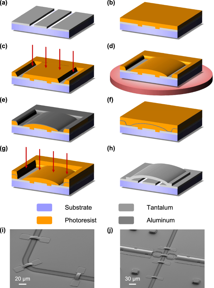
a Fabrication of the CPW layer with a 200 nm thick α-phase tantalum film on the sapphire substrate. Formation of the photoresist scaffold and base layer for airbridges with b spin coating, c exposure and d reflow of the first layer of photoresist. The red arrows in c denote the ultraviolet light, while the red disk in d represents baking at 140 °C. e Deposition of a barrier layer with 25 nm thick aluminum film. Formation of the bridge layer with f spin coating and g exposure of the second layer of photoresist. h Deposition of the tantalum airbridge with the niobium functioned as the seed layer after the ion milling of the CPW to ensure an electrical connection. i, j SEM images of tantalum airbridges with separate and fully-capped structures connecting the ground planes or two CPW center lines by lift-off method.
The presence of an aluminum barrier layer is necessary for the proposed lift-off method for several reasons. Firstly, it effectively prevents the mixing of the two layers of photoresist used in the recipe, as most types of photoresist are susceptible to blending, leading to pattern degradation during the spin coating of the second layer. Secondly, it provides protection for the arc-shaped scaffold created by the first layer of photoresist against exposure to the second one and eliminates potential damage caused by subsequent alkali development. Thirdly, after undergoing argon ion milling, a large amount of stubborn residual photoresist on sidewalls remains unremovable by solvents7. Fortunately, the barrier layer is usually over etched, leaving a small gap between the two layers of photoresist that effectively disconnects the stubborn residue and benefits a clean surface.
In practice, etching7 and grayscale lithography20,21 methods can also be employed for the fabrication of tantalum airbridges in principle. However, they may impose more stringent conditions on the tantalum film deposition compared to the proposed lift-off method. Considering the poor temperature resistance of photoresist, tantalum can only be deposited at room or low temperature, assisted by utilizing niobium as a seed layer for airbridges35,36. Meanwhile, corrugations may occur on the photoresist due to thermal effects during tantalum sputtering. Conversely, such thermal effects are absent in airbridge areas for the lift-off method since they contact the lower substrates, greatly simplifying the process.
Characteristics
To determine the appropriate design patterns and limits for fabricating airbridges, we systematically explored various lengths and widths using etching, grayscale lithography, and the proposed lift-off method. For airbridges with a height of 3 μm, the maximum length for achieving structural stability is limited to 60 μm based on etching and lift-off methods; however, when employing grayscale lithography, this limit can be extended to 200 μm, as illustrated in Fig. 2a, b. This discrepancy arises from the observation that beyond the length of 60 μm, plateaus appear in the profiles of photoresist scaffolds for those using etching or lift-off but not for grayscale lithography. We extracted the profile of photoresist sidewalls from a reflow surface and simulated scaffold profiles, which showed consistent evolution with experimental data (see Methods). This approach allows us to estimate the maximum length of an airbridge without conducting further experiments. In Fig. 2a, we compare these three methods, finding that the lift-off method is robust and fabrication-friendly, especially in constructing tantalum airbridges.
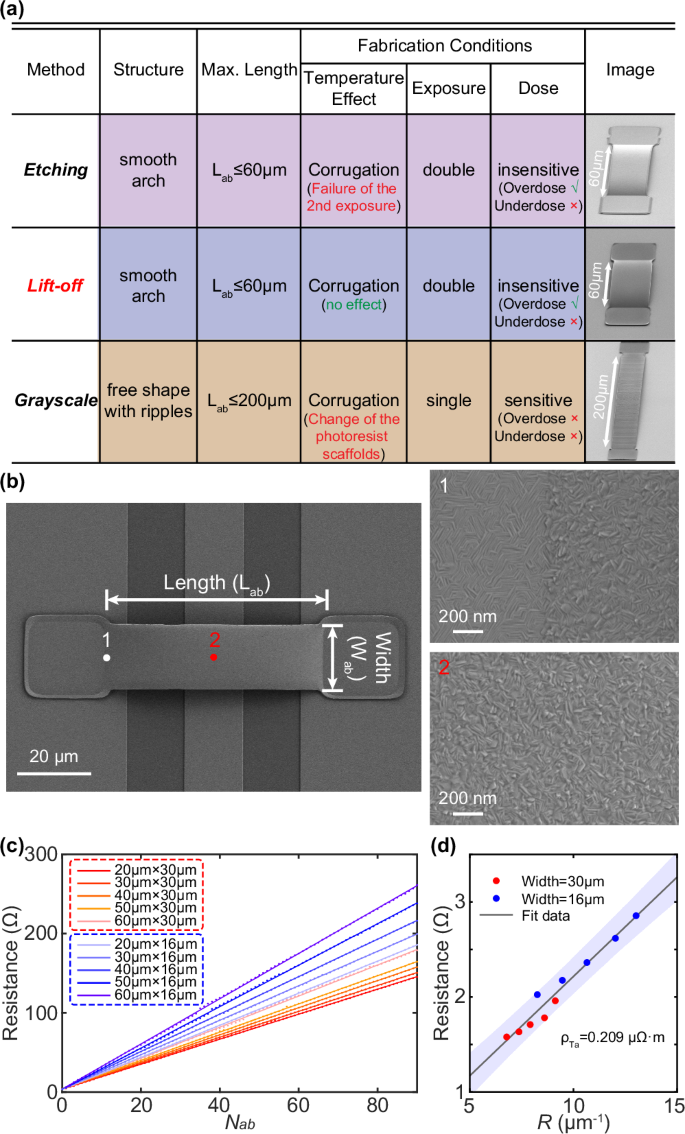
a Comparison among three fabrication methods for airbridges, where the “Max. Length” in the table denotes the length limitation to ensure intact airbridges with a fixed height of 3 μm and arbitrary width, and the “Temperature Effect” in “Fabrication Conditions” represents the potential issues occurred due to heating during film deposition. b SEM images of a single tantalum airbridge with the full structure shown in left panel and zoom-in structures shown in right panel. The length (Lab) and width (Wab) of the airbridge are defined as the white arrow in the left panel. c Measured resistance versus number of airbridges (Nab) with legend “Lab × Wab” of airbridges defined in (b). d Resistance of single unit versus resistance ratio R. The red and blue dots represent raw data acquired from airbridges with width of 30 μm and 16 μm respectively. The fitted line includes the 95% confidence interval, which is indicated by the shaded area overlaid on the data.
In addition, we carefully analyzed the crystal morphology of tantalum airbridges, as depicted in the right panel of Fig. 2b. The tantalum film on the base layer of airbridges shows a crystal grain similar to the α phase, while the tantalum film on top of airbridges differs from the typical α phase. The distinct grain structures observed at different positions can be attributed to variations in growth bases for the tantalum film; specifically, α-phase tantalum (amorphous photoresist) serves as the base for tantalum film grown on the base (bridge) layer. Consequently, our results suggest that both the deposition environment and base materials significantly influence the phase of tantalum films.
Figure 2c demonstrates the measurement of resistance for tantalum airbridge chains to analyze the connectivity with varied lengths and widths. It is observed that the total resistance of tantalum airbridges scales linearly with the number of airbridges. Here, the slope of the fitted line represents the resistance of a single unit, comprising a tantalum airbridge and a conducting pad, and we define a total resistance ratio R for each single unit as
where Lab (Lpad), Wab (Wpad), and tab (tpad) denote the length, width, and thickness of the airbridge (conducting pad) respectively. The slope of the fitted line is then extracted and plotted against the total ratio, as depicted in Fig. 2d. This analysis yields a resistivity value of ~0.21 μΩ m for each single unit. The small resistivity indicates good contact using tantalum airbridges.
Q
i measurement
To quantify the added capacitive loss from the tantalum airbridges at low temperature (~20 mK in the experiment), we fabricated a resonator chip containing seven λ/4 CPW resonators with various numbers of airbridges ranging from N = 0 to N = 90, as illustrated in Fig. 3a7,19. The airbridges were designed with a length of 60 μm and width of 16 μm, automatically arranged at equal distances using our homemade electronic design automation (EDA) tool for each resonator37. A zoom-in image displaying the arrangement of the airbridges is shown in Fig. 3b. Careful design considerations were taken into account for the resonators to ensure appropriate line width (also coupling quality factor Qc) that facilitates subsequent measurement of the internal quality factor (Qi). Furthermore, the resonance frequencies were uniformly distributed between 6.04 GHz and 6.64 GHz to avoid potential microwave electrical crosstalk19.
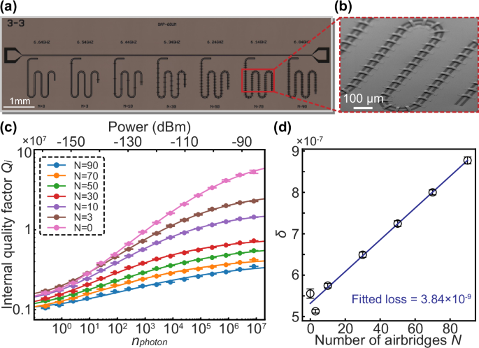
a Optical micrograph of one resonator chip with varied tantalum airbridges. The number of airbridges increases from N = 0 to N = 90 and the resonance frequencies are uniformly distributed between 6.04 GHz and 6.64 GHz. All the airbridges were designed with a fixed length of 60 μm and width of 16 μm, arranged at equal distances. b A zoom-in SEM image of the arranged tantalum airbridges circled by the red rectangle in (a). c Internal quality factor Qi versus average photon population (< {n}_{p} >) for each resonator. The error bars represent the uncertainty of Qi in the fitting process of S parameters. The solid lines are the fitting results obtained by the TLS model39. Notice that the overall Qi values tend to decline as the number of airbridges increases. d Loss tangent (1/Qi) versus number of airbridges. The fitted slope of line represents the added capacitive loss caused by a single airbridge to the CPW resonator.
The internal quality factor Qi was determined by measuring and fitting the S parameters of these resonators with varied drive power, allowing for a range of photon populations (< {n}_{p} >) in the resonator from single photon to high power photons38. Figure 3c presents representative Qi data for resonators with different numbers of airbridges. It is evident that at both low and high power, the trend of Qi exhibits two plateaus corresponding to TLS-determined behavior at around the single-photon level and TLS-saturated behavior at high power level. Additionally, the quality factor of the resonator increases as the drive power increases, consistent with the loss in the resonator being dominated by the two-level states at the material interfaces39, as depicted by the solid lines in Fig. 3c. For a tantalum resonator without added airbridges, the internal quality factor is measured to be 2.0 × 10⁶ at single-photon power and increases to 5.3 × 10⁷ at high photon power, consistent with the theoretical variation tendency. Similar trends are observed for tantalum resonators with a few tantalum airbridges. However, the overall Qi values appear to decrease with an increasing number of airbridges, indicating additional loss introduced by tantalum airbridges that can be further characterized by fitting the loss tangent (1/Qi) data. By observing the linear relationship between the number of airbridges and the loss tangent, we estimate an added loss per bridge of approximately (left(3.84pm 0.08right)times 1{0}^{-9}), demonstrating comparable low-loss and high-quality performance of tantalum airbridges to aluminum airbridges7,19.
Discussions
Our lift-off method for fabricating tantalum airbridges has been validated with a robust fabrication process, excellent connectivity, and minimal additional loss to the resonators. These findings suggest that they hold immense potential for widespread utilization in quantum processors40,41,42. To further demonstrate their capabilities, we explore two areas: signal crosstalk using fully-capped tantalum airbridges and direct coupling element employing well-designed tantalum airbridges.
We investigated the use of tantalum airbridges in a tunable coupling quantum processor based on a tantalum film and flip-chip architecture, which comprises 13 qubits and 16 couplers, as the schematic diagram shown in Fig. 4a43,44. All computational qubits are frequency-tunable transmon qubits, with grounded couplers enabling continuous adjustment of the effective coupling strength between qubits45,46. The design and optimization of the tantalum airbridges in this chip were achieved through a parametric EDA method, where the center line of the CPW can be automatically identified for the chip layout with wiring, followed by adding the airbridges accordingly37. The fabrication followed the proposed lift-off method depicted in Fig. 1 (the complete fabrication process of this 13-qubit quantum chip can be found in Supplementary Materials). Because of the resistance to acid and alkaline solutions, we could immerse the chip into piranha and HF solution to remove residual photoresist and eliminate the oxygen layer on the substrate after fabricating the tantalum airbridges—an option typically unavailable for aluminum airbridges. SEM images showcasing fully-capped tantalum airbridges wrapped around control lines are presented in Fig. 4b.
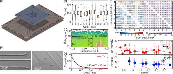
a Optical micrograph of the 13-qubit flip-chip processor. Here, the top chip is primarily used for qubit layer containing both Josephson junctions and shunt capacitors, while the bottom chip comprises readout resonators and control lines. Tantalum airbridges with fully-capped structure are incorporated over each control line to minimize crosstalk. b SEM images of the tantalum airbridges with fully-capped structure in (a). c A box plot of T1 results for all thirteen qubits, with a median T1 exceeding 100 μs for most qubits. Here, the box plot can illustrate the distribution of the data, with an interquartile range (IQR) of 1.5, indicating the range within which the middle 50% of the data lies. Meanwhile, the box represents the 25th percentile to the 75th percentile, and the whiskers extend to the minimum and maximum values, excluding any outliers. d Characterization of T1 measurement varied with qubit frequency for Q13. The inset illustrates the histogram with a median T1 of 109 μs. e A representative single T1 measurement result marked in (d). f Measurement of flux crosstalk (left panel) and microwave crosstalk (right panel) with tantalum airbridges utilizing the fully-capped structure. g Distance dependence of the flux crosstalk βz (top panel) and the microwave crosstalk ΛXY (bottom panel). The inset provides definitions for the distance d relevant to both types of crosstalk. Specifically, d(z) represents the shortest distance from the target qubit (i.e., the target SQUID) to the flux line, while d(xy) is defined as the center separation between the target qubit and the source qubit.
The fundamental performance of this flip-chip processor was characterized, with the results illustrated in Fig. 4c. It can be observed that most qubits exhibit a median T1 exceeding 100 μs extracted from the T1 distribution varied with qubit frequencies, see Fig. 4d as an example (Supplementary Materials provide complete data for other qubits). Meanwhile, a representative single T1 measurement is depicted in Fig. 4e. Notably, when TLS occurs at certain frequencies, a significant decline in population may occur, bringing detrimental effect to qubits47.
Moreover, we evaluated microwave and flux crosstalk between each control line. This crosstalk not only complicates the calibration of quantum circuits but also affects the fidelity of quantum gate operations, ultimately having a detrimental impact on the quantum computing process. Previous studies have indicated that crosstalk may be mitigated through active and passive methods, such as the implementation of a crosstalk matrix46,48,49,50,51,52.
While this approach can effectively reduce crosstalk levels, it requires significant time and resources, particularly as the number of qubits increases due to the quadratic scaling of experiments49. Here, we focus on the use of fully-capped airbridges, which provide complete coverage and shielding from microwave electrical signals7,40. We conducted crosstalk measurements on the chip, and the corresponding results are presented in Fig. 4f, revealing flux crosstalk less than 9.7 × 10⁻⁴ (median 1.4 × 10⁻⁴) and microwave crosstalk better than −30 dB (median −45 dB) (see Supplementary Materials for crosstalk measurement). To further explore the relationship between crosstalk and signal line separation, we sorted the crosstalk data in Fig. 4f combined with the distance between the target qubit and the source qubit. The results, shown in Fig. 4g, indicate that microwave crosstalk decreases with larger separation, with the fitted slope of average values being ~−6.6 dB/mm for the 13-qubit quantum processor. However, flux crosstalk presents a fluctuation pattern, which seems to be uncorrelated with distance.
Additionally, we have also noted a recent study that thoroughly examined the factors influencing crosstalk in signal lines within a flip-chip architecture53. By comparing quantum chips with and without airbridges, the authors analyzed the relationship between the suppression of microwave and flux crosstalk and the presence of fully-capped airbridges. Our findings align closely with theirs, particularly concerning the relationship between crosstalk and signal line separation. In fact, the mechanisms behind passive crosstalk suppression are complex. Current research does not definitively establish that fully-capped airbridges are always effective, as the factors influencing suppression are multifaceted. These factors may relate not only to the shielding effectiveness of the signal lines but also to the chip architecture (e.g., planar or flip-chip), the geometric structures on the chip (e.g., the routing of signal lines), the PCB of the sample box (including the inherent crosstalk of the PCB itself), and wire bonding techniques. Nevertheless, our experimental results offer valuable insights for future research on the impact of tantalum airbridges on crosstalk levels and their effectiveness in suppression.
We benchmark the single qubit gate fidelity using both isolated and simultaneous RB to assess the isolation of the fully-capped airbridges without compensating the microwave crosstalk. The median fidelity is found to be 99.95(2)% for isolated-RB and 99.94(2)% for simultaneous-RB. The similarity in these results suggests that our device exhibits low microwave crosstalk (see detailed data in Methods).
Furthermore, we discuss the coupling through airbridges. Superconducting qubits can typically be coupled through direct coupling54, coupler coupling40,46, resonator coupling32, or waveguide coupling55,56,57. For instance, the well-known surface code requires nearest neighbor qubit coupling, rendering direct or coupler coupling suitable choices58,59. However, long-distance qubit-qubit connections or fully-connected architecture requires the utilization of resonator or waveguide coupling. The resonators provide various geometrical options for connecting qubits but they also impose limitations on chip size and scalability. Recently, advancements in error correction codes, particularly quantum low-density parity check codes, have necessitated non-local (non-neighboring) qubit couplings for syndrome measurements, achieving a reduction of overall resource requirements24,25,26,27,28,29. Here, we propose a method for qubit interconnection using airbridges, which presents a potential solution for promoting non-local coupling by leveraging the spatial chip architectures.
Figure 5a illustrates a two-qubit superconducting quantum chip with tantalum airbridge-coupling fabricated via the lift-off method. We designed two groups of qubit pairs coupled with (experimental group) and without (control group) tantalum airbridges to benchmark the performance. We first characterized the effective coupling strength between these two qubits using airbridge coupling, as depicted in Fig. 5b. By tuning the frequency of one qubit to resonate with the other, the coupling strength can be extracted to be around 3.9 MHz, similar to that achieved in the control group. We then measured the coherence time of the qubits, as shown in Fig. 5c, finding that they are unlikely to be affected by introducing a tantalum airbridge for coupling, confirming its feasibility. Furthermore, the quality of such airbridge coupling was evaluated through a two-qubit CZ gate process. The flux pulses applied to each qubit were carefully designed with slowly changing waveforms and adjusted to generate resonance processes for states (leftvert 11rightrangle) and (leftvert 02rightrangle) (or (leftvert 20rightrangle)), followed by the accumulation of a π phase, thereby realizing standard diabatic CZ gate operation60,61. The fidelity for this two-qubit CZ gate was characterized through interleaved-RB, yielding 99.2(2)% as depicted in Fig. 5d, comparable to the one acquired from the control group. We also verified the entanglement capability by preparing a Bell state with such a CZ gate, achieving a state fidelity of 99.70% via quantum state tomography (QST), as illustrated in Fig. 5e.
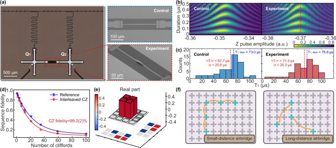
a Optical micrograph of the plane two-qubit superconducting quantum chip coupled via the separate tantalum airbridge, with fully-capped structure incorporated over each control line Zoom-in images of the coupling for both control group and experimental group are shown in the right panel respectively. b Characterization of effective coupling strength. The qubits in both groups are initially prepared in the (leftvert 01rightrangle) state (or (leftvert 10rightrangle) state), followed by fine-tuning the qubit frequencies to achieve resonance. The red dotted line in the experimental group represents the maximum resonance position where we extract the coupling strength to be 3.9 MHz. c T1 distribution for both control group and experimental group. Here the red and blue dotted line represent the extracted average T1 (〈T1〉) and median T1 (T1,Mdn), respectively. The standard deviation is also calculated as σ. It can be found that the coupling capacitor via airbridge seems to have little effect on qubit decoherence through comparison between control group and experiment group. d Interleaved-RB of diabatic CZ gate for the experimental group. The gate fidelity is measured at 99.2(2)% for both the experimental and the control group. e Preparation of Bell state (leftvert psi rightrangle =left(leftvert 01rightrangle +leftvert 10rightrangle right)/sqrt{2}) using CZ gate in (d) with state fidelity measured to be 99.70% via QST. f Schematic diagrams of the airbridge coupling mechanism in superconducting quantum processors. Here we consider two potential airbridge structures for coupling. Left panel: Small-distance airbridge (Lab ≤ 200 μm where Lab is defined in Eq. (1)) realizing neighboring or next-neighboring qubit-qubit connection. Right panel: Long-distance airbridge (Lab > 200 μm) realizing long distance qubit-qubit connection.
Finally, we present schematic diagrams in Fig. 5f to illustrate the application of the proposed airbridge-coupling mechanism in a multiqubit quantum chip featuring non-local couplings, where we propose two types of airbridges designed for effective coupling. It is crucial to consider potential spurious couplings when an airbridge spans over circuit elements within the quantum chip. For instance, when an airbridge crosses over a qubit, unintended capacitive interactions may occur, potentially causing the crossed qubit to act as a spectator qubit, which could adversely affect quantum gate operations between the qubits connected via the airbridge. To mitigate such effects, several strategies can be employed. One effective approach is to design the chip layout such that airbridges do not directly cross over qubits but rather over couplers. Since couplers typically remain unexcited during quantum operations and their idle frequencies are generally far removed from those of the qubits, the risk of spurious coupling induced by the airbridge can be significantly reduced. However, the issue of spurious coupling still warrants further investigation and research, particularly in the context of employing airbridges for non-local coupling processes62. Moreover, the long-distance airbridges depicted in Fig. 5f demonstrate the capability to span extensive distances on the chip, which could be critical for future applications in large-scale quantum computing and quantum error correction. Therefore, continued enhancements in airbridge design and fabrication techniques, including the development of new bridge structures63 and the optimization of lift-off or grayscale lithography processes62, remain important areas for further exploration.
In summary, we propose and develop a novel lift-off method for fabricating tantalum airbridges with a separate and fully-capped structure. We compare three fabrication methods, including etching, grayscale lithography, and the proposed lift-off. We verify the robustness of our approach under varied fabrication conditions, with an emphasis on temperature control during film deposition. Furthermore, the excellent performance and versatility of these tantalum airbridges as control line jumpers and ground plane crossovers are illustrated through connectivity tests, Qi measurement of CPW resonators, and crosstalk calibration. To demonstrate the scalability and adaptability of tantalum airbridges in multiqubit fabrication processes, we present a 13-qubit tunable coupling superconducting quantum processor equipped with fully-capped tantalum airbridges based on tantalum films, with median T1 exceeding 100 μs for most qubits, and consistent single-qubit gate fidelity for isolated-RB and simultaneous-RB. Finally, we explore the application of tantalum airbridges in coupling mechanism, achieving measured two-qubit CZ gate fidelity of 99.2(2)% without sacrificing coherence time. Our results demonstrate the reliability of the lift-off method for fabricating tantalum airbridges and its potential broad applications in quantum computation and quantum error correction.
Methods
Airbridge simulation
We have mentioned that for etching and lift-off methods, the maximum length for a structurally stable airbridge is ~60 μm, while it increases to 200 μm for airbridges fabricated by grayscale lithography. Hence, we hypothesize that the stability of the airbridge is influenced by the corresponding profile of the photoresist scaffold. To investigate this behavior, we simulate the formation of the scaffold. We judge that the arch-shaped scaffold is formed by adding two profiles of the edge scaffold with opposite directions after reflow. Therefore, we extract the edge profile of the reflowed photoresist and simulate the profile of the scaffold by adding two edge profiles together. The overlap distance of two profiles represents the length of the airbridge, and the sum height of profiles is the simulated profile of the scaffold. By approaching two edge profiles with different distances, we can obtain profiles of scaffold with different airbridge lengths.
For the etching and lift-off methods, an arch-shaped scaffold is formed by combining two edge profiles with opposite directions after undergoing a high-temperature reflow process. By extracting and simulating these edge profiles together, we find that they are nearly the same across different lengths of airbridges. The simulated profiles consistently align with experimental data (Fig. 6a, b), revealing the appearance of plateaus in scaffolds when exceeding 60 μm in length. These plateaus could potentially explain why longer airbridges become unstable. We also extract height information from our simulated scaffolds and qualitatively compare it with the experimental data with various lengths, as depicted in Fig. 6d. Meanwhile, for grayscale airbridges in Fig. 6c, where exposure gray values precisely define their profile, a parabolic shape remains consistent regardless of length.
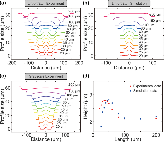
a Experimental profiles of airbridge scaffolds for etching and lift-off methods. b Simulated profiles of scaffold for etching and lift-off methods. c Experimental profiles of airbridge scaffold for grayscale lithography method. Notice that curves in (a), (b), and (c) have been shifted for clarity and the length of the airbridges are also marked beside each curves. d The height of the airbridges versus the length for both experimental and simulation data.
These results suggest that the edge of the photoresist plays a crucial role in determining scaffold structure and ultimately affects the stability of airbridges depending on its characteristics such as having an elongated tail-like feature. During the reflow process, arch-shaped edges are formed. Consequently, by adjusting the reflow temperature, it is possible to systematically modify the profile of edge scaffold. Utilizing the simulation described above, one can roughly estimate the maximum achievable lengths for stable airbridges after reflow without compromising structural integrity.
Parallel single-qubit gate operations
Quantum circuits can be executed more efficiently by running quantum gates in parallel. However, this parallel quantum computation is vulnerable to correlated errors such as microwave crosstalk and stray coupling40,59. To assess the effectiveness of tantalum airbridges and tunable couplers in mitigating these errors, we benchmark the single-qubit gate performance using both isolated and simultaneous RB40, as depicted in Fig. 7b. The idle frequencies of all thirteen qubits are also presented in Fig. 7a for reference. Our result demonstrates a small increase (0.013%) in single-qubit gate error probabilities, indicating that our device exhibits low microwave crosstalk and stray coupling.
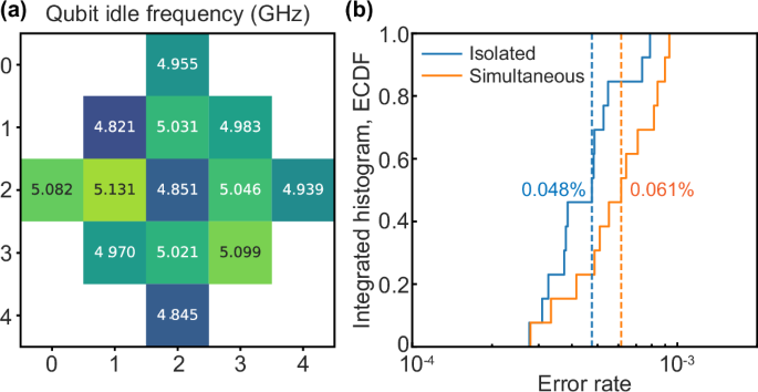
a Idle frequencies for all qubits when performing parallel single-qubit gate operation. b Integrated histogram (empirical cumulative distribution function, ECDF) of single-qubit Pauli errors, measured via isolated (blue) and simultaneous (orange) RB. The median of each distribution occurs at 0.5 marked by the dotted line with 0.048% for isolated-RB and 0.061% for simultaneous-RB (average values are similar).
Responses