Temporal signal processing with nonlocal optical metasurfaces

Introduction
Optical computing has recently gained renewed interest1 due to the continued improvements in nanofabrication and to the exponentially growing demand for data processing, especially in the context of neural networks2 and neuromorphic computing3,4,5. As compared to electronics, optical computation offers the advantages of a much larger bandwidth and spatial parallelism, which can lead to higher throughputs and reduced latencies1. Moreover, the nearly lossless nature of light propagation can lead to large reductions in energy consumption and heat generation, which are some of the main limits of modern electronic processors. While building general-purpose optical processors is still out of reach, there is a strong interest in implementing special-purpose analog optical devices1 performing specific operations on the incoming signals, working in parallel with electronic hardware to accelerate specific tasks or lowering the burden on digital processing. For example, neural networks and neuromorphic computing necessitate massively parallel signal processing, including detection of temporal variations of signals, and they may largely benefit from the possibility of offloading some of these tasks into high-speed analog optical devices with zero energy consumption and ultrafast speeds.
Signal and image processing in the analog domain based on Fourier optics concepts has been proposed and extensively studied in the last decades6. The underlying idea is to decompose a signal into its spatial and/or temporal frequency components via optical elements, such as lenses and diffraction gratings, and then selectively filter these components with the aid of spatially varying masks. Notable examples of these approaches are 4f systems for spatial image processing7 and pulse shapers for the manipulation of temporal signals8,9. While versatile and easy to implement, these approaches ultimately suffer from the need of using bulky optical elements, which strongly increase the overall system footprint and prevent compactification, while also being prone to alignment issues. In recent years, it has been suggested that Fourier-based image processing can be implemented in sub-wavelength planarized patterned devices, known as metasurfaces10,11. In particular, nonlocal metasurfaces can act directly in the Fourier space of an input signal, thus implementing on-demand filtering of the Fourier spatial components without the need for bulky optical elements. Several theoretical10,11,12,13,14,15,16 and experimental17,18,19,20,21,22,23,24 studies have indeed demonstrated that mathematical operations, such as spatial differentiation, can be imparted on the incoming wavefront using metasurfaces. The key idea of these approaches is to transform the desired spatial operation in its Fourier counterpart, and then encode it into the angle-dependent transfer function of a metasurface.
While metasurface-based Fourier processing has been extensively investigated for spatial operations and image processing, comparatively little effort has been devoted to temporal operations using nonlocal metasurfaces. Similar to their spatial counterpart, linear temporal operations can be implemented by transforming the desired operation into a multiplicative polynomial factor in the temporal Fourier domain, and then encoding such a factor into the frequency-dependent transfer function of the metasurface through dispersion engineering. In other words, by tailoring its frequency nonlocality, a metasurface can act as a compact spectral filter performing time-domain computations without the need for pulse shapers and diffraction gratings, within a deeply subwavelength overall footprint. Recent theoretical works have investigated temporal signal processing with graphene25,26 or dielectric27 structures, including a recent experimental demonstration at radio frequencies28. Theoretical studies have also investigated metasurfaces performing linear combinations of spatial and temporal differentiation29,30,31,32,33, especially geared towards the generation of spatio-temporal optical vortices34. Similar concepts have been demonstrated in integrated photonics35,36,37,38 using ring resonators and Mach-Zehnder interferometers as dispersive elements, and in radio-frequency circuits39. Yet, an experimental demonstration of free-space temporal differentiation and processing of optical signals with metasurfaces is lacking. We note that recent works have demonstrated spatio-temporal light shaping using spatially-varying metasurfaces as masks inside traditional pulse shapers40. These approaches are attractive because of the increased versatility of metasurfaces in engineering the complex transfer amplitude. However, the underlying need for additional diffraction gratings and lenses sets hard bounds on the minimal footprints of the overall device, and may introduce relevant alignment issues.
Here, we demonstrate a nonlocal metasurface performing analog temporal differentiation of free-space signal ({S}_{{in}}(t)) carried by optical waves with wavelength ({lambda }_{0},approx ,800) nm (Fig. 1a). In stark contrast from approaches based on pulse shapers8,9,40, here the computation is fully performed within a deeply subwavelength metasurface with thickness ({H},approx ,{lambda }_{0}/5), without the need for additional optical elements (Fig. 1a). We achieved this functionality by tailoring the metasurface nonlocality in time, so that its transfer function follows the trend (tleft(omega right)propto left(omega -{omega }_{0}right)) around a certain operating frequency ({omega }_{0}). Such transfer function results in the first-order differentiation of input signals, modulating the impinging wave in the time domain. We experimentally characterize the response of our metasurface for different types of input pulses, and quantitatively show that the mathematical operation encoded in the transmitted signal is very close to the exact first-order derivative. As a possible application, we demonstrate that our device can be used for temporal edge detection: the filtered signal features large spikes at the same instants of time when the input signal undergoes large variations. Moreover, we quantitatively characterize the metasurface efficiency — i.e., we compare the power carried by the filtered signal with the power of the input signal — showing that the efficiency of our device is less than a factor of 2 smaller than the efficiency of any ideal passive differentiator with the same bandwidth. Finally, we experimentally demonstrate the potential of this approach for scalability and cascaded operations, showcasing how multiple metasurfaces, each performing the first-order derivative, can be cascaded without requirements on their precise positioning, resulting in an overall device that performs higher-order differentiation. As we discuss below, the metasurface design demonstrated here can be readily adapted for operations in different regions of the electromagnetic spectrum. Moreover, the approach demonstrated here can be readily extended to metasurfaces with isotropic unit cells17,22,23,41, which would lead to a polarization-independent and isotropic response.

a A signal Sin(t) (e.g., a square pulse) is encoded in the envelope of an electromagnetic wave impinging on a metasurface. The envelope of the transmitted wave is the first-order derivative of the input pulse, dSin(t)/dt. b Geometry of the unit cell of the nonlocal metasurface. See text for design parameters. c Calculated amplitude (solid blue line) and phase (solid orange line) of the transfer function of the metasurface. The dashed lines are fits of the corresponding data. Here and in all other panels the impinging electric field is parallel to the metasurface wires (y-direction). d Calculated response of the metasurface in panels (b, c) when a signal with amplitude Sin(t) (red shaded area) is impinging. The blue line shows the calculated output field amplitude Sout(t), while the green curve shows the analytically calculated value of dSin(t)/dt. The inset shows that Sout(t) and dSin(t)/dt are delayed by about 45 fs. e SEM images of a fabricated device. Scalebars = 1 µm. f Measured transmission amplitude of the fabricated device (solid line), together with a linear fit (dashed line).
Results
In order to perform time differentiation of an incoming pulse, the metasurface must support a properly tailored transfer function (t(omega )). Indeed, the transfer function (t(omega )) dictates how the metasurfaces affects different frequency components of the impinging pulse. Thus, to perform a desired mathematical operation on the impinging pulse, (t(omega )) needs to reproduce the Fourier-domain representation of that mathematical operation. The first-order time differentiation of the envelope of a pulse, i.e., the operation (sleft(tright){e}^{i{omega }_{0}t}to left[frac{d}{{dt}}sleft(tright)right]{e}^{i{omega }_{0}t}), is represented in Fourier space by the multiplicative operation (widetilde{s}left(omega right) rightarrow -ileft(omega -{omega }_{0}right)widetilde{s}left(omega right)), where (widetilde{s}left(omega right)) is the Fourier transform of (s(t)). Thus, neglecting an overall phase factor, we aim at designing a metasurface with a transfer function ({t}_{{target}}left(omega right)propto left(omega -{omega }_{0}right)) around a certain target frequency ({omega }_{0}).
Our metasurface design (Fig. 1a, b) consists of a resonant waveguide grating (RWG) made of a high-refractive-index material placed on a quartz substrate. In this study we chose titanium dioxide (TiO2) as a high-refractive index material, mainly due to its negligible loss in the visible and near-infrared range. However, our approach is agnostic to the specific materials, and it can be readily extended to other material platforms. For operation in the telecommunication band, for example, the RWG could be made of amorphous or crystalline silicon. Figure 1b shows the unit cell of the optimized metasurface. It consists of a grating with lattice constant p = 475 nm, wire width w = 345 nm and depth h = 100 nm partially etched into a TiO2 slab with total thickness H = h + t = 160 nm. Via a systematic parameter sweep, we optimized the geometrical parameters such that the normal-incidence response of the metasurface resemble closely the target transfer function ({t}_{{target}}left(omega right)) around a central frequency of ({omega }_{0}/2pi ={f}_{0},approx ,375,{rm{THz}}), corresponding to a wavelength ({lambda }_{0}approx 800,{rm{nm}}), while simultaneously supporting no diffraction orders in either the superstrate or substrate. In the following simulations and experiments, the impinging field is polarized along the grating wires (y-direction in Fig. 1b). Figure 1c shows the calculated amplitude (solid blue line) and phase (solid orange line) of the metasurface transfer function for normal incidence. As confirmed by the simulated data (solid lines) and fits (dashed lines), within a certain range of frequencies (Delta omega /2pi =Delta fapprox) 6 THz (denoted by the grey shaded area) the transfer function can be approximated by (tleft(omega right)=A{e}^{iomega tau }left(omega -{omega }_{0}right)) (dashed lines in Fig. 1c are fits), where (tau approx 45{fs}). Thus, if an electromagnetic wave with carrier frequency ({f}_{0}) and with envelope ({S}_{{in}}(t)) with spectrum defined within ([{f}_{0}-Delta f/2,{f}_{0}+Delta f/2]), impinges on the metasurface from one side, the envelope of the transmitted wave is expected to be proportional to the first-order derivative of ({S}_{{in}}(t)) delayed by (tau ,) i.e. ({S}_{{out}}left(tright)propto {S}_{{in}}^{{prime} }(t-tau )). This is verified numerically in Fig. 1d. Here, we considered an input signal ({S}_{{in}}(t)) (red shaded area) containing pulses with different shapes. We calculated the output field ({S}_{{out}}(t)) produced by the metasurface (solid blue line) assuming the realistic transfer function shown in Fig. 1c, and we compare it to the exact first-order derivative (d{S}_{{in}}/{dt}) (solid green line). The field created by the metasurface precisely follows the first-order derivative of the input field, except for a delay of (tau approx 45 ; {rm{fs}}) (see inset of Fig. 1d), as expected.
Following this optimization, we fabricated TiO2 metasurfaces with geometrical parameters close to the simulated ones (see Methods for details). Figure 1e shows SEM micrographs of a fabricated device. The measured normal-incidence transmission spectrum (Fig. 1f) confirms that the transmission amplitude follows the expected (left|tleft(omega right)right|propto |omega -{omega }_{0}|) dependence within a (Delta f) = 6 THz range centered around ({omega }_{0}/2pi ={f}_{0}=373;{rm{THz}}). As compared to simulations, the minimum of the measured transmission amplitude is not zero, due to fabrication imperfections and sub-idealities in our setup. Nonetheless, the minimum transmission (T={left|tleft(omega right)right|}^{2}) is below 7%, ensuring a good suppression of the DC component of the signal envelope.
In order to experimentally verify the temporal signal processing operation of our nonlocal metasurface under different excitations, we used the custom-build setup schematized in Fig. 2. To generate input signals ({S}_{{in}}(t)) with arbitrary temporal shapes and large spectral bandwidths, we used the output of a CW mode-locked Ti:Sapphire laser (repetition rate 76 MHz, central wavelength 800 nm) as a broadband source. The laser produces positively chirped pulses with a duration of 120 fs and a bandwidth of Δν = 5.43 THz. A prism compressor42 was used to re-compress the pulses to quasi-Fourier-transform-limited pulses with a duration Δτ (approx) 8 fs (time-bandwidth product Δτ·Δν (approx) 0.43). Such compressed pulses [labelled ({I}_{p}(t)) in Fig. 2] were sent onto the input port of a beamsplitter and split into two copies. One copy of the pulse (‘reference’ in Fig. 2) was sent through an optical delay line, and then into the reference port of an optical cross-correlator (OCC). Another copy of the pulse was sent into a custom-built pulse shaper8,9 (red-shaded area in Fig. 2 labelled “Input Pulse Preparation”). Here, the different spectral components of the pulse ({I}_{p}(t)) were spatially separated by a diffraction grating and a lens, filtered by a mask, and then recombined by a second set of diffraction grating and lens. In such a way, different desired input pulses ({S}_{{in}}(t)) can be generated using masks with different spatially varying transmission profiles. The input pulse ({S}_{{in}}(t)) is then directed onto the metasurface with a long-focal-length lens (f = 50 cm). The signal processed by the metasurface ({S}_{{out}}(t)) was then collected on the other side by a second lens and sent either onto a spectrometer or onto the input port of the OCC. The voltage signal produced by the OCC is proportional to the convolution of the reference pulse intensity ({I}_{p}(t)) and the intensity ({I}_{{out}}left(tright)propto {left|{S}_{{out}}left(tright)right|}^{2}) of the output signal, i.e., ({V}_{{out}}left(tau right)propto int {dt},{I}_{p}left(tright){I}_{{out}}(tau -t)). Thus, by working with narrow reference pulses ({I}_{p}(t)), the cross-correlation trace (CCT) ({V}_{{out}}left(tau right)) allows retrieving the field amplitudes (|{S}_{{out}}(t))|. In order to experimentally measure also the input field ({S}_{{in}}(t)), we laterally translated the metasurface sample, so that the input field ({S}_{{in}}(t)) impinged on an area of the sample with unpatterned 160-nm-thick TiO2. Here, the spectral response of the sample is flat, and thus, apart from an intensity attenuation of less than 4%, the transmitted field is equal to ({S}_{{in}}(t)). Therefore, the corresponding CCT ({V}_{{in}}left(tau right)) allows us to retrieve the field amplitude (|{S}_{{in}}left(tright)|). The reference pulse ({I}_{p}(t)) was only used in conjunction with the OCC, and it was instead ignored when measuring the spectra of the input and output pulses with the spectrometer.
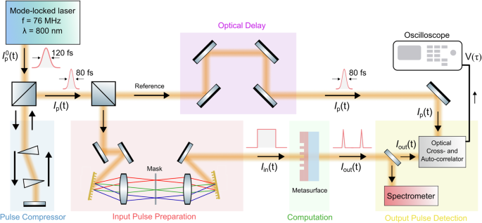
The 120-fs pulses generated by a mode-locked laser are first compressed (to about 80 fs) by a prism-based pulse compressor and then split into two copies with a beam splitter. One copy, ({I}_{p}(t)) is delayed by a controllable optical delay and then sent to the reference port of an optical cross-correlator. The other copy is redirected to a pulse shaper, which is used to generate input pulses ({I}_{{in}}(t)) with arbitrary temporal shapes. The input pulse is then sent to the metasurface. The pulse ({I}_{{out}}(t)) is sent either to a spectrometer or to the second port of the cross correlator. See text for additional details.
We emphasize that, while the experimental setup in Fig. 2 involves several bulk components and may appear fairly complex, the analog computation occurs only within the sub-wavelength metasurface (green-shaded area labelled “computation” in Fig. 2). All other parts of the setup are used either to prepare a certain input pulse of interest or to detect the output signal and verify the metasurface operation, but they do not play any role in the computation of the first-order derivative. In particular, we emphasize that the output pulse (containing the first-order derivative of the input pulse) is already created and well-defined immediately after the metasurface, and no other bulk optics (such as diffraction gratings or lenses) are required to generate the final pulse. In a practical setup, the signal processing metasurface can be placed anywhere in front of a detector to impart the desired mathematical operation on the impinging signals.
By using the setup in Fig. 2, we have tested the response of the metasurface under different input signals. In Fig. 3a, we consider the case a rectangular pulse with duration of approximately 1 ps as the input signal. This pulse was produced using, in the pulse shaper, a mask imparting a transmission profile proportional to ({sinc}(x))9. Figure 3a shows the CCTs of the input signal (red-shaded area) and of the output signal (solid blue line), multiplied by 10. As expected from a first-order differential operation, the output signal features two high-contrast peaks at the same temporal positions where the intensity of the input signal changes from zero to a finite value or vice versa. Instead, at the time in which the intensity of the input field envelope remains approximately constant, the output signal is almost zero. The residual non-zero signal in the output field is due to the fact that the experimental transfer function (Fig. 1f) is not exactly zero at (f={f}_{0}), leading to a partial transmission of the DC component of the input signal envelope. The experimental results in Fig. 3a show that our metasurface performs temporal edge detection, in analogy with the spatial edge detection recently reported using nonlocal metasurfaces performing the Laplacian operation. Similar results are obtained when the input is a rectangular pulse with a longer duration of 2 ps (Fig. 3b). In this case, a larger background signal between the two peaks is observed in the output signal (solid blue line in Fig. 3b). This feature is expected since the input signal bandwidth is narrower in this scenario, hence the output signal is affected more pronouncedly by the non-zero transmission at (f={f}_{0}). We also considered a rectangular pulse with asymmetric edges (Fig. 3c), obtained by intentionally misaligning the corresponding ({sinc}(x)) mask in the pulse shaper. As expected, the edge with steepest slope (close to time t = −1 ps) leads to a stronger peak in the output signal, while the other edge, close to time t = 1 ps and characterized by a gentler slope, gives rise to a much less intense signature in the output signal.
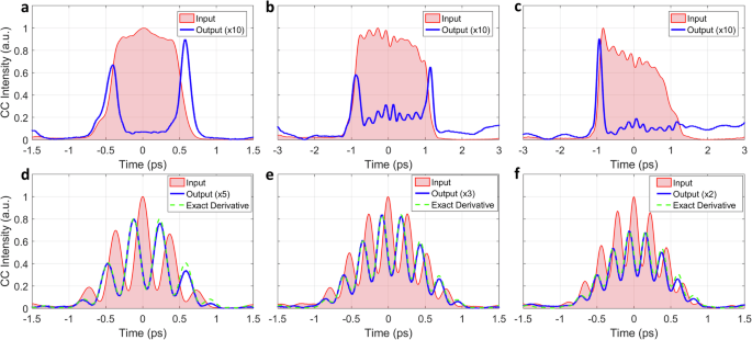
In all panels, the red-shaded areas show the CCT of the input pulses, and the blue solid lines show the CCT of the output pulses. In panels d-g the green dashed curves show the CCT calculated for the exact first-order derivatives of the input pulses (see text for details). The measured output pulse intensities have been rescaled by different factors to aid visualization (see each legend for the corresponding factor). a–c The input pulse is a rectangular pulse with duration 1 ps (a) or 2 ps (b). In (c), we intentionally displaced the phase mask in the pulse shaper to create an asymmetric pulse. d, e The input pulses are obtained by the beating of two quasi-monochromatic pulses with frequency detuning (varDelta). The detunings are (d) (varDelta =2.65) THz, (e) (varDelta =3.75;textrm{THz},,left({mathbf{{f}}}right),varDelta =4.42;) THz.
Next, we verify the computational capability of the nonlocal metasurface with more complex input signals, which also allows us to verify that the performed mathematical operation is very close to the exact first-order derivative. We consider input pulses obtained by the beating of two quasi-monochromatic waves with frequencies ({f}_{0}pm Delta /2). In our experiments, these pulses were obtained by placing an opaque mask with two pinholes in the pulse shaper, to select only two narrow frequencies. By changing the distance between the pinholes, different beating frequencies (Delta) can be generated. Figure 3d–f show the experimental results for three different input pulses, with beating frequencies (Delta =2.65) THz (Fig. 3d), (Delta =3.75) THz (Fig. 3e), (Delta =4.42) THz (Fig. 3f). In all cases, the CCTs of the input signal (red-shaded areas) show the expected cosine-like shape, with the maximum intensity at t = 0 and additional peaks separated by (Tequiv 1/Delta). In each measurement in Fig. 3d–f, the output CCT (solid blue line) displays an oscillatory pattern, with maxima almost aligned with the minima of the corresponding input CCT (red-shaded area). This pattern matches the behavior expected from the squared modulus of the derivative of a cosine-like function. The measurements in Fig. 3d–f also confirm the presence of a systematic delay: in each measurement, the central minimum of the output CCT (solid blue lines) systematically lags behind the maximum of the corresponding input CCT. By comparing the positions of these features in all traces in Fig. 3d–f, we estimate a delay of about ({tau }_{exp }=47) fs, in very good agreement with the delay (tau =45) fs extracted from simulations in Fig. 1c. Finally, we compare the experimental data with the CCT theoretically expected if the output field was the exact first order derivative of the input field. To do so, we use a procedure described in detail in the Methods and summarized here: we first built an ansatz for the input field ({S}_{{in}}(t)), given by the sum of two Gaussian pulses with carrier frequencies ({f}_{0}pm Delta /2), and we constructed the corresponding CCT, ({V}_{{in}}^{{fit}}left(tau right)). This function was then used to fit the measured CCTs of the input fields, ({V}_{{in}}left(tau right)) (red-shaded areas in Fig. 3d–f). This allowed us to retrieve several parameters in the ansatz for ({S}_{{in}}(t)). We then analytically calculated the delayed first-order derivative (d{S}_{{in}}(t-{tau }_{exp })/{dt}) and the corresponding CCT. The CCTs obtained with this procedure are plotted as green dashed lines in Fig. 3d–f, showcasing excellent agreement with the measured CCTs of the signal processed by the metasurface (blue lines). This provides an indirect confirmation that the signal processing performed by the metasurface closely matches the desired first-order differentiation. We also note that the output fields in Fig. 3e, f are much less affected by the unwanted background signal that was obtained in Fig. 3a, b. Indeed, for the input signals considered in Fig. 3e, f, the input spectrum peaks at the beating frequencies ({f}_{0}pm Delta /2). Thus, the unwanted non-zero transmission of the metasurface at ({f}_{0}) has a negligible impact on the quality of the output field.
The results in Fig. 3 confirm that our metasurface can perform first-order differentiation of different input pulses with high fidelity. Yet, the peak power of the output pulses is typically reduced as compared to the input peak power (note that in each measurement in Fig. 3 the intensity of the output pulse has been rescaled to aid visualization, with the scaling factor reported in each legend). The reduced output power represents a potential challenge for the use of these metasurfaces within more complex computational platforms, especially in scenarios when multiple computational metasurfaces are cascaded, as discussed below. While this issue can be partially overcome by improving the metasurface design, we emphasize that the reduced output power is, in fact, mainly due to a fundamental limitation set by passivity. In particular, for any linear passive device (that is, a device which does not require any bias or energy consumption) the transfer function must satisfy (left|tleft(omega right)right|le 1) for any frequency. This implies that the optimal transfer function (tleft(omega right)=Aleft(omega -{omega }_{0}right)) (where A is a proportionality factor) can be obtained only within a finite bandwidth (Delta omega equiv left|{omega }_{max }-{omega }_{0}right|) such that (Delta omega le 1/A).
In fact, we can show that the efficiency of our passive metasurface is quite close to the efficiency of an ideal passive device with the same bandwidth. To demonstrate this, we performed a systematic investigation of the metasurface computational efficiency, i.e., how the intensity of the output signal compares to the intensity of the input signal. As discussed above, there is an absolute limit on the efficiency set by passivity, that depends on the nature of the performed operation (a time derivative is a high-pass filter, hence it naturally is expected to suppress a portion of the input energy). Moreover, the metasurface dispersion implies that the overall efficiency also depends on the bandwidth of the input signal. In particular, while we can expect differentiation for any signal whose bandwidth is equal to or smaller than the frequency range for which (tleft(omega right)propto left(omega -{omega }_{0}right)), we also expect higher efficiencies for signals whose spectra covers this entire range of frequencies, such that the spectrum edges, corresponding to spikes triggered by fast changes in the input signals, experience close to unitary transmission. To study this effect experimentally, we used input pulses with a Gaussian-like temporal shape and continuously varying spectral bandwidths. These pulses were generated by using a slit with variable width as a mask in the pulse shaper. Figure 4a–f show the experimental results for six different spectral bandwidths. In each panel, the left sub-panel shows the normalized spectra of input (red-shaded areas) and output (blue solid lines) signals. The bandwidth of the input signals (measured as FWHM of the corresponding spectrum) ranges from 5.2 THz in Fig. 4a to 1.5 THz in Fig. 4f. The spectrum of the output signals (blue lines in left panels) confirms that the metasurface strongly suppresses transmission at frequencies close to ({f}_{0}approx 373{rm{THz}}), as expected. The right sub-panel of each Fig. 4a–f shows the measured input and output CCTs (similar to the plots in Fig. 3). In all six cases, the input signal resembles a Gaussian pulse with additional weaker tails. The output signals indeed consist of two main peaks which, apart from the expected delay ({tau }_{exp },approx ,47) fs, are located at the temporal positions where the input signal has the largest slope. To quantify the metasurface efficiency, we consider the metric ({eta }_{mathrm{int}}equiv int {dt}{V}_{{out}}left(tau right)/int {dt}{V}_{mathrm{int}}left(tau right)), defined as the ratio of the integrated input and output CCTs. In the limit of very short reference pulses ({I}_{p}left(tright),) this metric is equal to the ratio between the energies carried by the input and output pulses. In Fig. 4g we plot (blue circles) the efficiency ({eta }_{mathrm{int}}) calculated for all measurements in Fig. 4a–f (and for other measurements not shown here) as a function of the spectral bandwidth of the input signal. As clearly shown from this plot, the efficiency increases with the bandwidth of the input pulse, as expected, ranging from ({eta }_{mathrm{int}}=1.4 %) for a bandwidth of 1.2 THz to ({eta }_{mathrm{int}}=24 %) for a bandwidth of 5.25 THz. As mentioned, the increase of efficiency with bandwidth is expected because, as the spectral bandwidth of the input pulse increases, its Fourier spectrum captures more and more the high-transmission regions of the metasurface transfer function (Fig. 1f). As the spectral bandwidth of the input pulses increases further and becomes larger than the operational bandwidth of the nonlocal metasurface (Δf = 6 THz for this device, see also Fig. 1f), we expect to observe unwanted distortions from the expected differentiation operation. In the temporal domain, this upper bound on the pulse bandwidth translates into a lower bound on the duration of pulses which can be correctly processed. Specifically, as the duration of the input pulses becomes shorter than (T sim 1/varDelta f,approx ,0.2) ps, the output pulse is expected to deviate from the exact first order derivative. We emphasize that, apart from such upper bound on the spectral bandwidth, there are no other limitations on the input pulse spectrum. In particular, while most of the experimental examples shown here focus on input pulses with spectra which are symmetric around the carrier frequency ({f}_{0}), this is not a necessary condition, and input pulses with strongly asymmetric spectra will also be correctly processed by our metasurface.
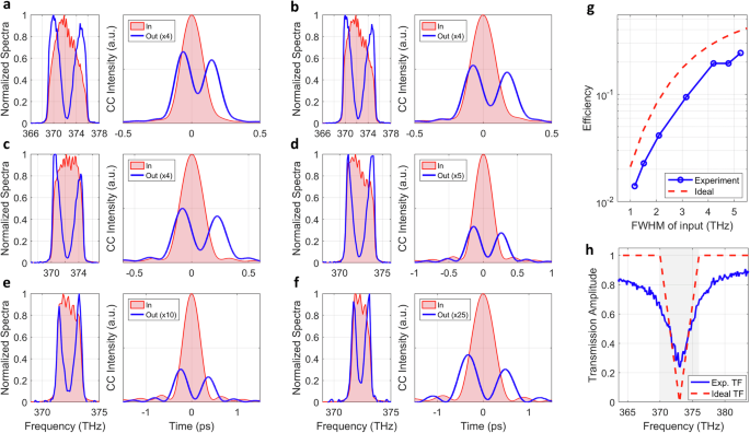
a–f Experimental measurements of the metasurface response for input pulses with different bandwidths. In each panel, the left sub-panel shows the frequency spectrum of the input pulse (red-shaded area) and the filtered pulse (blue solid line). The right sub-panel shows the corresponding CCTs. g Computational efficiency, defined as the ratio between the energies of the output and input pulses, versus the bandwidth of the input pulse, extracted for the experimental data (solid blue line) and calculated for an ideal differentiator with the same bandwidth as our metasurface. h Absolute value of the transfer function in the experiment (solid blue line), compared to the transfer function of an ideal differentiator with a bandwidth of 6 THz (dashed red line). See text for additional details.
We stress again that the sub-unity values of efficiency measured in our experiments are not associated to a poor implementation of the metasurface, but rather to the fact that a derivative operation implemented via passive components expectedly produces an efficiency drop. Dealing with dielectric metasurfaces, material absorption is negligible, and the bulk of the power loss is actually reflected by the metasurface in order to to filter out the DC component of the input signal. In fact, and quite remarkably, the efficiency of our metasurface is very close to the efficiency of an ideal passive differentiator device with the same bandwidth. To show this, we consider an ideal differentiator described by a transfer function ({t}_{{ideal}}left(fright)=2(f-{f}_{0})/Delta f) when (fin [{f}_{0}-Delta f/2,{f}_{0}+Delta {rm{f}}/2]), and (|{t}_{{ideal}}left(fright)|=1) otherwise. The central frequency ({f}_{0}=373) THz and bandwidth (Delta f=6) THz are chosen to match the ones of the measured device. The transfer function (|{t}_{{ideal}}left(fright)|) is plotted in Fig.4h (dashed red line), together with the measured transfer function (|{t}_{{meas}}left(fright)|) (solid blue lines). By using Gaussian pulses with different values of FWHMs as test input signals, we calculated the efficiency of such ideal differentiator as a function of the bandwidth of the input pulse. The results (red dashed line in Fig. 4f) confirm that the experimentally measured efficiency of our metasurface is less than a factor of 2 lower than the efficiency of an ideal differentiator with the same bandwidth. Thus, our realistic device is already performing close to the maximum theoretical efficiency allowed by passivity. The efficiency of the metasurface can be increased (up to the limit set by the dashed red curve in Fig. 4g) by further improving the design such that the metasurface transmission spectrum (blue curve in Fig. 4h) resembles more closely the optimal response (red dashed line in Fig. 4h).
Our nonlocal metasurface can perform high-efficiency first-order temporal differentiation of an optical signal within a subwavelength footprint ((Happrox {lambda }_{0}/5)), in contrast with other metasurface-based implementations which rely on pulse shapers and bulky optics. The extreme compactness of our platform provides a natural opportunity to scale optical computing tasks in a modular fashion, i.e., by cascading multiple elements. To demonstrate this feature, we performed an experiment where two metasurfaces, each separately performing first-order differentiation, are cascaded (Fig. 5a), and we verified that the operation imparted by the overall device is proportional to the second-order derivative of the input. The first metasurface (MS1) is the same as the one used for the experiments in Figs. 3 and 4. The second metasurface (MS2) had a nominally identical design as MS1, but fabricated separately. As input signal, we considered the same cosine-like signal used for the experiment in Fig. 3d (the corresponding CCT is shown in Fig. 5b as red-shaded area). We first tested each metasurface separately and confirmed that the output signals created by either MS1 or MS2 (solid and dashed blue lines in Fig. 5b) are almost identical, and they match the first-order derivative of the input signal (compare also with Fig. 3d). Then, we cascaded MS1 and MS2 (Fig. 5a, see Methods for more details on the setup) and we repeated the experiment with the same input signal. In the experiment (Fig. 5a), the metasurfaces were kept parallel to each other and separated by a distance of about 1 mm, but remarkably the output is not affected by the relative positioning of the two elements. Such a relatively large gap was only dictated by practical mechanical constraints of our setup, and it can be reduced to a few wavelengths without impacting the optical behavior. The measured output CCT (red solid line in Fig. 5c) displays the features expected from the second-order derivative of the cosine-like function used as input (red-shaded area in Fig. 5c). In particular, both input and output fields feature the same number of peaks, and with the same relative heights. The output is delayed by approximately (2tau =94) fs with respect to the input, as expected from the two-metasurface arrangement. To confirm quantitatively that the output produced by the cascaded arrangement is the second-order derivative, we calculated the expected CCT for the exact second-order derivative of the input signal, following the same procedure used in Fig. 3(d–f). The result of this calculation, shown as dashed green line in Fig. 5c, matches almost perfectly the measured output CCT (red solid line). As mentioned above, one of the main challenges of using these devices for cascaded operations is that, due to the absence of any bias and electronic amplification, the energy of the output pulse (after each step) is reduced as compared to the input energy. In the experiment in Fig. 5, the peak power of the output pulse produced by two cascaded metasurfaces is reduced by a factor of ~20x as compared to the original input pulse. As mentioned above, the throughput efficiency of our metasurface is approximately 50% of the one of an ideal passive differentiator. Thus, improvements in the metasurface design (such that the metasurface transfer function in Fig. 4h matches better the ideal transfer function) could lead to a possible 4x enhancement of the efficiency of the two-device cascaded systems, and an increase of approximately ({2}^{n}) for a system of n cascaded devices.
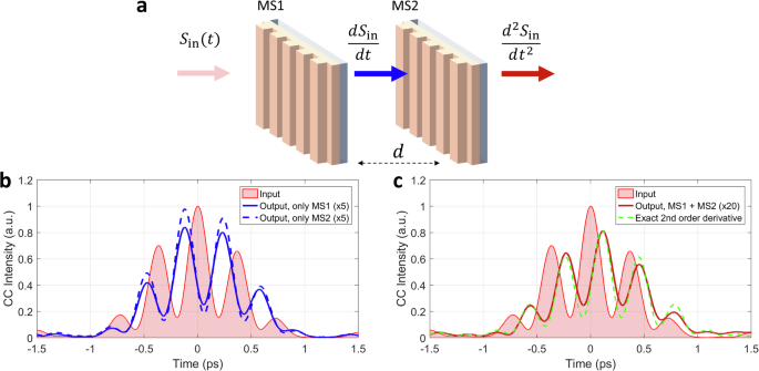
a Two similar metasurfaces, each of them performing first-order differentiation, are cascaded. The resulting device performs second-order differentiation. b Response of each metasurface. The input field (red shaded area) is the same as the one used in Fig. 3d. The solid and dashed blue lines show the CCT of the output fields produced by each metasurface separately. c Response of the cascaded system. The solid red line shows the output CCT when the input field impinging on the cascaded arrangement. The dashed green line shows the calculated CCT for the exact second-order derivative of the input field.
Discussion
We have proposed and experimentally demonstrated a deeply subwavelength nonlocal metasurface that can perform analog first-order differentiation on the envelope of an optical signal. The functionality was achieved by engineering the temporal nonlocality of the metasurface, in order to tailor its frequency-dependent transfer function. Importantly, differently from approaches based on pulse shapers8,9,40, in our experiment the computation is entirely performed by a single metasurface with thickness (Happrox {lambda }_{0}/5), and it does not require any additional optical element. We measured the metasurface response for different types of input pulses, confirming that the performed operation is very close to the exact first-order derivative. Our metasurface can be used to perform analog temporal edge detection, i.e., it can be used to identify the instant of times at which a signal is strongly varying. Moreover, thanks to the design simplicity and the absence of material loss, our metasurface features large integrated efficiency. Finally, we experimentally demonstrated that our device offers a natural platform to implement cascaded operations in a modular fashion, i.e., by physical cascading multiple metasurfaces. As a practical example, we showed that when two metasurfaces, each performing first-order derivative, are cascaded, the resulting device performs second-order differentiation.
Our results provide the first experimental demonstration that nonlocal metasurfaces can perform analog temporal operations on optical signals without the need of bulky optical setups, resulting in an extremely compact free-space computational block. The specific functionality demonstrated in this work — temporal edge detection — can be readily extended to metasurfaces with spatio-temporal nonlocalities to perform event-based detection33 and analog neuromorphic computing. Moreover, the simplicity of the design introduced here makes it compatible with other material platforms (such as silicon, in order to work at operating wavelengths ({lambda }_{0}approx 1550) nm) and with different tuning approaches41,43, paving the way for reconfigurable computing with metasurfaces. Finally, while for simplicity in this work we focused on an anisotropic metasurface design made of a 1D grating, the same functionality can be obtained in 2D metasurfaces with higher degrees or rotational symmetry. In particular, a polarization-independent and isotropic response can be obtained by working with metasurfaces made of photonic crystals with C6 rotational symmetry22,23,41. Thanks to their reduced footprint, their bias-free operation and their ease to implementing scalable and cascaded operations, we envision that these devices will be adopted as building blocks within more complex optical computing platforms, especially in scenarios where low energy consumption and very low latency times are critical, such as neural networks and neuromorphic computing.
Methods
Numerical Simulations
The metasurface geometry was optimized by performing numerical electromagnetic simulations with Comsol Multiphysics 6.1. The calculations in Fig. 1d were performed with a Matlab script, by calculating the Fourier transform of a given input signal, multiplying it by the metasurface transfer function calculated with Comsol (Fig. 1c), and then applying the inverse Fourier transform.
Fabrication
The metasurfaces were fabricated with a standard top-down lithographic process, starting with commercially available TiO2-coated glass substrates (MTI Corp). The TiO2 layer was first etched to the achieve the desired thickness H = h + t (see Fig. 1c). A 20 nm-thick layer of chromium was deposited via e-beam evaporation, and a 300 nm-thick layer of e-beam resist (ZEP 520-A) was spin-coated on top of the samples. The metasurface pattern was written with an electron beam tool (Elionix 100 keV). After development, the pattern was transferred to the chromium layer via a Cl2 − O2 dry etching process performed in an ICP machine (Oxford PlasmaPro System 100). After removing the ZEP mask, the pattern was transferred to the TiO2 layer with a CF4−Ar−O2 dry etching process performed in the same ICP machine. In this step, the TiO2 was etched to a depth equal to h (see Fig. 1b). The residual chromium mask was removed via wet etching.
Optical characterization
The normal-incidence transmission spectrum in Fig. 1f was measured with a custom-built setup. A collimated broadband lamp was weakly focused on the metasurface with a long-focal-length lens (f = 20 cm), and the beam transmitted through the sample was collected by an identical lens (L2) and sent onto the input slit of a visible spectrometer (Ocean Optics, HR 4000).
All time-domain measurements in Figs. 3–5 were performed with the setup shown in Fig. 2 and described in the text. To create pulses with different temporal profiles, we used spatial masks with different shapes in the pulse shaper. The masks required to create the beating pulses (Fig. 3d–f and Fig. 5) were obtained by drilling pairs of holes with diameter of 0.77 mm onto a thick metallic slab. To create the pulses with variable bandwidth (Fig. 4), we utilized a continuously variable mechanical slit (Thorlabs, VA100). To create rectangular pulses, we used a spatially varying mask that imparts a transmission profile proportional to (sin left({kx}right)/x), where x is a spatial coordinate along the mask and (k) is a coefficient that determines the pulse duration. The mask was realized by cascading two masks, following the procedure described in ref. 44. The first mask, which imparts the transmission amplitude profile (propto |sin left({kx}right)/{x|}), consisted of metallic gratings with variable duty cycles. The second mask, which imparts the required binary phase profile (propto angle (sin left({kx}right)/x)), was obtained by etching rectangular apertures onto a substrate of silicon oxide.
Data analysis
In Figs. 3d–f and 5c we showed the numerically calculated output cross-correlation traces (CCTs) for the case in which the input fields are given by the beating of two beams with different frequencies. The CCTs were calculated by assuming that each metasurface performs the exact first-order derivative of the input signal, according to the following procedure. We assumed that the electric field pulse created by the pulse shaper is given by the sum of two gaussian pulses,
The central frequency ({f}_{0}) and the detuning between the beams (Delta) can be retrieved independently from spectroscopic measurements. The parameters ({tau }_{1}) and ({tau }_{2}) describe the bandwidth of each beam, and they are mainly determined by the width of the pinholes in the mask. The parameters ({A}_{1}) and ({A}_{2}) describe the relative amplitudes of each beam, and only their ratio ({A}_{1}/{A}_{2}) is of practical importance here. The narrow reference pulse (used in the experiment to produce the CCTs) is described by
where we assume ({tau }_{{ref}}=80{fs}) based on the independent characterization of the reference pulse. We used this ansatz to calculate the expected CCT of the input field, ({V}_{{in}}^{{calc}}left(tau right)=int {dt}{I}_{{in}}(t){I}_{{ref}}(tau -t)), where ({I}_{{in}}left(tright)={left|{E}_{{in}}left(tright)right|}^{2}) and ({I}_{{ref}}(t)={|{E}_{{ref}}(t)|}^{2}). By comparing the calculated ({V}_{{in}}^{{calc}}left(tau right)) with the measured CCT of the input field, we were able to estimate with high accuracy all remaining parameters in the expression for ({E}_{{in}}left(tright)). In particular, for all cases considered here we found that the experimental data are well fitted by assuming that the two beams have the same amplitude (({A}_{1}={A}_{2})), the same bandwidth (({tau }_{1}={tau }_{2},approx ,0.98{rm{ps}})) and the same phase ((phi =0)). After having fully determined ({E}_{{in}}left(tright)), we calculated numerically the first-order derivative of its envelope, i.e. (gleft(tright)=frac{d}{{dt}}[{E}_{{in}}left(tright){e}^{-i2pi {f}_{0}t}]), and we used it to construct the expected output electric field ({E}_{{out}}left(tright)=gleft(tright){e}^{i2pi {f}_{0}t}). Finally, we calculated the expected CCT of the output field, ({V}_{{out}}^{{calc}}left(tau right)=int {dt}{I}_{{out}}(t){I}_{{ref}}(tau -t)), where ({I}_{{out}}left(tright)={left|{E}_{{out}}left(tright)right|}^{2}). The green dashed lines in Fig. 3d–f correspond to the curve ({V}_{{out}}^{{calc}}left(tau right)) calculated with this procedure and rescaled vertically by an overall factor. For the case of the second-order derivative (green dashed lines in Fig. 5c) we followed the same procedure outlined above, but now (gleft(tright)=frac{{d}^{2}}{d{t}^{2}}[{E}_{{in}}left(tright){e}^{-i2pi {f}_{0}t}]).

Responses