THz generation by exchange-coupled spintronic emitters

Introduction
Terahertz (THz) radiation refers to a part of the electromagnetic spectrum that typically covers frequencies between 300 GHz and 30 THz. Strong interest in developing reliable versatile THz sources stems from the properties of THz radiation that allow unprecedented insight into otherwise inaccessible phenomena in physics1,2,3,4,5,6,7,8,9, chemistry10,11,12,13, biology14,15,16,17,18, astronomy, and materials science19,20,21 with a breakthrough potential in a broad range of applications ranging from wireless communication22,23,24 to medicine diagnostics17,18,25. The full control over the THz generation, detection, polarization state as well as the frequency range is crucial for efficient use of THz radiation in compound-selective chemical imaging, genetic diagnostics or a free-space communication26,27. The THz spectral range is particularly attractive for probing interactions in new materials, providing meV and fs resolution in the energy and time space, respectively28,29. An overview of physical mechanisms that have been employed for generation of THz transients can be found in19.
In F/M bilayers superdiffusive spin currents (JS)30,31,32,33,34 triggered by femtosecond laser pulses in a ferromagnetic layer can be converted into a charge current (({{boldsymbol{J}}}_{{rm{C}}}^{{rm{ISHE}}})) in the adjacent metallic layer by the inverse spin Hall effect (ISHE)35,36,37.
The acceleration of electrons forming ({{boldsymbol{J}}}_{{rm{C}}}^{{rm{ISHE}}}) generates THz transients that can be either guided along a chip using transmission lines12,38,39,40 or propagate into free space1. The efficiency of the THz generation is primarily governed by the spin polarization (σ), which is given by magnetization (M), and by the spin Hall angle (θSH), the value of which is determined by the strength of the spin-orbit coupling (SOC) in the metal layer1,41,42,43,44,45,46. According to35,47, ({{boldsymbol{J}}}_{{rm{C}}}^{{rm{ISHE}}}) is perpendicular to both M and JS, following
where ℏ is the Planck constant.
The attractiveness of the optically triggered spintronic emitters stems from a relative simplicity of their design, the tunability of the THz amplitude and polarization, and the compatibility with the standard fabrication technologies. THz radiation has been shown to be easily controllable by a broad range of parameters including magnetic field1,41,42,43,44,48,49,50,51,52,53, laser fluence42,42,54, choice of thin-film F and M materials37, temperature49,55,56, excitation wavelength57,58, film thicknesses42,45,49,50,57,59,60,61, patterning62, and light polarization63.
Several groups worldwide have demonstrated THz emission from more complex layered structures in order to either toggle the spin emitter output between the high- and low-amplitude THz intensity states64, to increase THz intensity in synthetic antiferromagnets65,66, or to enhance the overall absorption of the excitation light by covering the emitter with additional dielectric multilayers58.
In the present work, we show that THz radiation generated by MgO//Pt/Fe/Cr/Fe/Pt exchange-coupled spintronic (ExCES) emitters can be tuned using interlayer exchange coupling (IEC) and weak magnetic fields. The emitters show the maximum THz output near zero external field and the minimum at saturating magnetic fields. We ascribe the observed functionality to the interference of THz transients generated simultaneously in closely spaced emitters by a single laser pulse.
Results
Exchange-coupled spintronic emitter – principle of operation
The principle of operation of a THz emitter based on the MgO//Pt/Fe/Cr/Fe/Pt multilayers is shown in Fig. 1. Fabrication details are in the Methods. In Fig. 1 we assume that the ISHE mechanism in Pt layers dominates THz generation as reported in, e.g.,37,45 or53. We first neglect THz generation in the Cr layer and assume that the films and interfaces fabricated from the same materials are identical. The arrows and superscripts indicate the directions of MFe, ({{boldsymbol{J}}}_{{rm{S}}}^{{rm{Fe}}}), and ({{boldsymbol{J}}}_{{rm{C}}}^{{rm{Pt}}}) in the Fe and Pt layers.

The layer sequence consists of two Pt/Fe and Fe/Pt emitters, exchange-coupled by a wedge-shaped Cr spacer and, arranged in a mirror-like geometry with respect to the Cr layer. The thickness tCr of the Cr spacer varies from 3 to 0 nm. Black arrows mark the magnetization direction of Fe layers MFe and the spin currents JS flowing from Fe to Pt. Green arrows mark the direction of charge currents JC. The parallel (a) (antiparallel (b)) alignment of JC results in strong (weak) THz transients due to THz transient superposition. In the figure, ISHE is assumed as a main mechanism and only spin currents flowing from Fe to the neighboring Pt layers are drawn for clarity.
The Cr spacer mediates RKKY-type indirect IEC67 between the two Fe layers, which leads to oscillations between ferro- and antiferromagnetic coupling, depending on the Cr thickness68. In zero external magnetic field, this results in either M↑↑ or M↑↓ relative magnetization alignment in the Fe layers along the Cr wedge. In the M↑↑ case [Fig. 1(a)], MFe1 and MFe2 point in the same direction. Due to the layer stacking, and following Eq. (1), the currents ({{boldsymbol{J}}}_{{rm{S}}}^{{rm{Pt1}}}), ({{boldsymbol{J}}}_{{rm{S}}}^{{rm{Pt2}}}) (and ({{boldsymbol{J}}}_{{rm{C}}}^{{rm{Pt1}}}), ({{boldsymbol{J}}}_{{rm{C}}}^{{rm{Pt2}}})) point in mutually opposite directions. Resulting THz transients with opposite polarities therefore interfere destructively, yielding a minimum THz output.
In contrast, in the M↑↓ case [Fig. 1(b)] following the same arguments, transient currents ({{boldsymbol{J}}}_{{rm{C}}}^{{rm{Pt1}}}), ({{boldsymbol{J}}}_{{rm{C}}}^{{rm{Pt2}}}) point in the same direction. In this case, THz transients add constructively and generate the resulting THz transient with the maximum amplitude ({{boldsymbol{A}}}_{max }).
Figure 2a shows the longitudinal magneto-optic Kerr effect (L-MOKE) signal from an ExCES THz emitter as a function of external field μ0H at one chosen Cr layer thickness tCr = 1.45 nm (L-MOKE measurement is described in Methods). L-MOKE hysteresis rounding and a reduced remnant magnetization ({M}_{R}^{+,-}approx) 0.4 × Msat implies a largely antiparallel M alignment or formation of a multi-domain region within the laser illumination spot. The full set of L-MOKE hystereses for 3 nm > tCr > 1 nm range is shown in Figure S1. The set illustrates how the varying tCr affects the shape of magnetic hysteresis and ({M}_{R}^{+,-}).
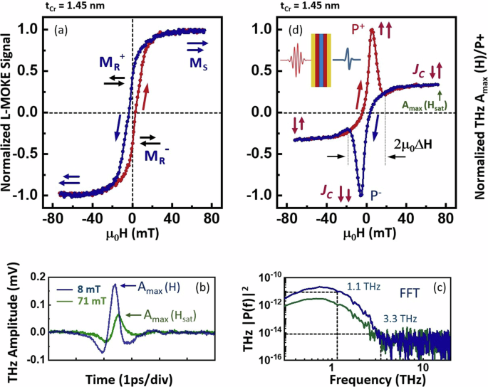
a shows magnetic field dependence of L-MOKE signal at tCr = 1.45 nm. The hysteresis loop shows reduced remnant magnetizations marked ({M}_{{rm{R}}}^{+}) and ({M}_{{rm{R}}}^{-}) due to antiparallel alignment of the Fe layers’ magnetization. The red and blue symbols and the long tilted arrows mark the directions of the magnetic field sweep. b THz transients generated by the ExCES THz emitter at μ0H = 8 mT (blue) and μ0H = 71 mT (green). The clearly different maximum amplitudes ({A}_{max }(H)) are marked by blue and green arrows. c The corresponding FFT power spectra show 3 dB cut-off at 1.1 THz for both magnetic fields. d Field dependence of the THz maximum peak amplitude ({A}_{max }(H)) generated by the ExCES THz emitter at tCr = 1.45 nm. Pairs of short red arrows mark the relative ({{boldsymbol{J}}}_{{rm{C}}}^{,{rm{Pt1}}}) and ({{boldsymbol{J}}}_{{rm{C}}}^{,{rm{Pt2}}}) alignment that results in weak (antiparallel alignment) and strong (parallel alignment) THz generation. P+ an P− denote the peak values of the ({A}_{max }(H)) curve for increasing and decreasing field. ({A}_{max }({H}_{{rm{sat}}})) denotes the THz amplitude in saturation field, i.e., ({A}_{max },({H}_{{rm{sat}}})={A}_{max },({mu }_{0}H=71,{rm{mT}})). The magnetic field tunability range 2 μ0 ΔH is marked by black arrows. The displayed trace shows up to 300% THz signal enhancement at μ0H = ±8 mT with respect to ({A}_{max }({H}_{{rm{sat}}})), at this particular tCr.
Figure 2b shows THz transients generated by the ExCES emitter at tCr = 1.45 nm for two magnetic fields μ0H = 8 mT and μ0H = 71 mT. By comparing the transients, it is clear that the lower magnetic field results in a significantly higher ({A}_{max }). The corresponding FFT power spectra in Fig. 2(c) show no significant differences, both featuring 3- dB cut-off at 1.1 THz and signal extinction at a noise onset at 3.3 THz. The THz measurement schematics is shown in Fig. S2.
An evolution of the peak THz amplitude in a varying magnetic field ({A}_{max }(H)) is displayed in Fig. 2d. It reveals a hysteretic behavior which stands in a stark contrast not only with the L-MOKE loop in Fig. 2a, but also with a typical ({A}_{max }(H)) curve generated by a single-bilayer F/M spintronic emitter52,53. In Fig. 2(d), we note that as the magnetic field varies between ± Hsat, ({A}_{max }(H)) shows first a minimum, which is subsequently, followed by a sharp enhancement to about 3(times {A}_{max }({H}_{{rm{sat}}})) near μ0H ≈ +8 mT. The further increase of the magnetic field leads to an ({A}_{max }(H)) drop, ultimately reaching the minimum at the positive magnetic field saturation. The reverse magnetic field sweep ({A}_{max }(H)) mirrors the one that has just been described. The figure also defines P+ and P− as the ({A}_{max }(H)) maxima and the magnetic field tunability range 2 μ0 ΔH, the parameters that are described in more detail below.
THz amplitude control via Cr-spacer thickness
Figure 3 illustrates how the ({A}_{max }(H)) varies with tCr. This is most apparent in the 2.1 nm ≥ tCr > 0.9 nm range, where (leftvert {A}_{max }(H)rightvert) at tCr = 1.35 nm shows up to fourteen fold enhancement relative to the ({A}_{max }({H}_{{rm{sat}}})). Nearly all ({A}_{max }(H)) hysteresis curves show P+ and P− that also vary with tCr. Figure 4a shows the evolution of P+ and P− along the Cr wedge thickness (full circles and lines). In order to assess the performance of an ExCES THz emitter as an amplifier, we define a figure of merit, FOM (={P}^{+,-}/{A}_{max }({H}_{{rm{sat}}})) at each tCr. Figure 4b shows that the strongest amplification corresponds to FOM ≈ 14 that is reached near tCr ≈ 1.2 nm, suggesting that it corresponds to the near-optimum M↓↑ and M↑↑ alignment for the current batch of emitters.
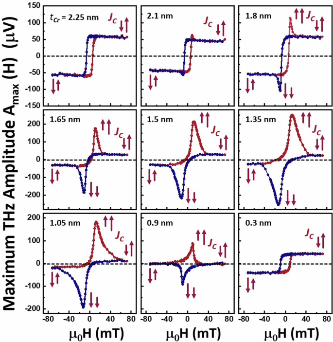
The joint effect of the external field and IEC leads to an enhancement (suppression) of the THz peak amplitude at Cr thicknesses favoring an antiparallel (parallel) magnetization alignment. The pairs of short red arrows mark the relative alignment of ({{boldsymbol{J}}}_{{rm{C}}}^{,{rm{Pt1}}}) and ({{boldsymbol{J}}}_{{rm{C}}}^{,{rm{Pt2}}}).
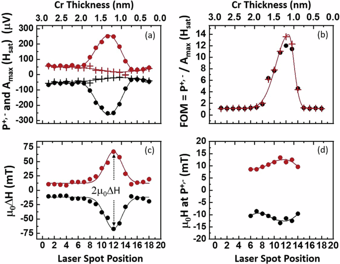
a Variation of the peak value of the maximum THz amplitude ({A}_{max }(H)), marked P+,− [see Fig. 2d] with tCr for both increasing (red symbols)- and decreasing magnetic field sweeps (black symbols). ({A}_{max },({H}_{{rm{sat}}})) are plotted as red and black crosses. The lines serve as a guides for the eyes. b Figure of merit [FOM = ({P}^{+,-}/{A}_{max }({H}_{{rm{sat}}}))] as a function of tCr for increasing (red crosses) and decreasing (black dots) field sweeps shows an optimum FOM near tCr = 1.2 nm. c Variation of the field tunability 2 μ0 ΔH with tCr [for the definition of the field tunability see Fig. 2d]. d The magnetic field at which the THz amplitude reaches maximum P+ (red symbols) or minimum P− (black symbols) varies with tCr .
Finally, Fig. 4(c) shows 2 μ0 ΔH quantifying the interval of magnetic fields needed to switch the magnetization of the Fe layers from M↓↓ to M↑↑ configuration. In fact, 2 μ0 ΔH(tCr) curves, in terms of the shape and peak position, strongly resemble the tCr-dependence of the IEC constant of similarly fabricated Fe/Cr-wedge/Fe structures presented in Figure 7 of68. Direct comparison is shown in Figure S3.
Discussion
In order to understand the generation of the THz transients in ExCES emitters, we calculated the relative alignment of magnetization vectors MFe1, MFe2 by numerically solving the equation for the free energy density E(θ1, θ2) for all possible magnetization angles θ (for a detailed description see Methods). The simulations show that MFe1 and MFe2 align co-linearly at ± μ0Hsat and adopt a V-shaped configuration with respect to the magnetic field direction in the − μ0Hsat < μ0H < + μ0Hsat range. Selected snapshots and the evolution of the relative alignment of MFe1, MFe2 in the full range of magnetic fields are shown in Figure S4 and the movie in Figure S5. Our simulation also suggests that the antiparallel M↑↓ configuration is attained at μ0 H = 0 mT, resulting the THz signal maximum P+ (or P−). In contrast, in the experiment the maxima are reached near μ0 H ≈ ± 8 mT [Fig. 4d]. We ascribe this shift to the coercivity and asymmetry in magnetic properties of the two Fe films. This can arise as a consequence of different growth conditions on different substrates for the Fe1 vs. Fe2 and may include differences in the magnetic anisotropy, lattice matching or atomic-level interface smoothness.
The simulations also show that although at μ0 H = 0 mT, MFe1 and MFe2 are mutually aligned in perfect antiparallel configuration, they are not parallel to H but are tilted by approximately 45 degrees with respect to H direction (Figure S4). This configuration, which is stabilized by the easy axes of the in-plane magnetocrystalline anisotropy, leads to a drop in the measured THz intensity component ({E}_{{rm{y}}}^{{rm{THz}}}) (perpendicular to H) to about 70% due to the rotation of the THz polarization away from the high sensitivity THz detector-axis (see Methods subsection Experiment:THz measurement). Moreover, due to this tilt, the ({E}_{{rm{x}}}^{{rm{THz}}}) component parallel to H can be detected by simply rotating the high-sensitivity axis of the THz detector by 90 degrees, as illustrated in Figure S6. ({E}_{{rm{x}}}^{{rm{THz}}}, < ,{E}_{{rm{y}}}^{{rm{THz}}}) suggests that the overall magnetization tilt is either nearly parallel to μ0 H or it has a broad asymmetric V-shaped arrangement even at the ({E}_{{rm{y}}}^{{rm{THz}}},) signal maximum.
The performance parameters displayed in Fig. 4a–c show t Cr-dependencies with the maxima centered around t Cr = 1.2 nm, except of ({A}_{max }({H}_{{rm{sat}}})) which shows a minimum [crosses in Fig. 4 (a)]. We note that while the ({A}_{max }({H}_{{rm{sat}}})) minimum is reached at the parallel alignment of MFe1, MFe2 enforced by external magnetic fields ± μ0 Hsat, the maxima are due to the antiparallel alignment enforced by IEC near μ0 H = 0. The fact that both the maximum and the minimum of ({A}_{max }({H}_{{rm{sat}}})) occur at the same t Cr indicates optimum- and nearly identical interface properties near t Cr ≈ 1.2 nm. The small external field μ0 H that is needed to reach the M↑↓ or M↓↑alignment slightly varies with t Cr as well [Fig. 4(d)] reflecting subtle variations of the energy landscape with t Cr.
Although the performance of ExCES THz emitters is predominantly governed by external magnetic field and by IEC, additional tunability can be achieved by the fabrication process (see Methods). The latter can strongly affect magnetic properties of Fe films as well as transmission, reflection and scattering of JS and JC at the F/M interfaces. A close look at the ({A}_{max }(H)) dependence reveals that ExCES emitters show only a single THz enhancement during the − μ0Hsat to + μ0Hsat and + μ0Hsat to − μ0Hsat sweeps (marked by the red and blue symbols, respectively, in Fig. 3). This is in contrast to a bipolar THz signal enhancement expected for the symmetric IEC supporting two mirrored antiparallel M↑↓ alignments at positive and negative field66. We therefore simulated the behavior by numerically adding the ({A}_{max }(H)) signals of two separate real emitters that were fabricated using the exactly same fabrication process as the complete structure of the ExCES emitter. The calculated sum ({A}_{max }(H)) qualitatively follows the ExCES emitter performance reproducing the single enhancement per magnetic field sweep (Figure S7). Hence, the unipolar shape of the ({A}_{max }(H)) sweeps can be traced back to different coercivity of the Fe layers in real emitters, an effect that is not described by the simulations (see Methods).
Relatively recent reports indicate, that a F/M interface can contribute substantially to THz generation even in case of low SOC. The possible mechanisms include the skew scattering52,69 and the spin-sink effect70,71. We consider thermo-electric30,72,73,74 and laser-driven demagnetization36,75,76,77,78 effects to be negligible for ExCES emitters due to very thin metallic layers preventing a build-up of thermal gradients and a low excitation power of the laser.
In order to check experimentally the impact of the Fe/Cr interface we fabricated a new Pt(2)/Fe(2) bi-layer and covered one half of it with 3-nm Cr layer. The entire structure was fabricated in-situ and protected by a 3-nm-thick MgO film. Compared to the Fe/Pt – side, the Pt/Fe/Cr side reveals an overall drop of ({A}_{max }(H)) by about 30%. In the ISHE picture, the THz amplitudes from Pt/Fe and Fe/Cr emitters add due to the opposite sign of θ SH. The observed drop suggests the presence of additional mechanisms. Following the laser excitation, a fraction of JS in the Pt/Fe/Cr structure superdiffuses into Cr, in contrast to Pt/Fe/MgO, where the entire JS enters the Pt layer. The fraction of JS that passes through the Fe/Cr interface can generate a THz transient with the opposite polarity via skew scattering52,69. In addition, the Cr-induced spin-sink effect earlier described in70 and71 can reduce JS in Pt resulting in a further overall drop of the THz amplitude.
In conclusion, our measurements show that controlling the magnetic configurations in our ExCES emitters permits convenient tunability of the THz radiation amplitude and polarization via IEC and weak external fields. Compared to simpler spintronic THz emitters based on soft ferromagnet/heavy metal bi-layers, ExCES THz emitters show a complementary behavior of ({A}_{max }(H)), i.e., they demonstrate low THz amplitude at large magnetic fields μ0 H → μ0 Hsat and the THz maximum near μ0 H = 0 mT. In addition, our ExCES emitters show up-to 14-fold enhancement of the THz amplitude ({A}_{max }(H))/ ({A}_{max },({H}_{sat})) for the M↑↓ vs the M↑↑ configurations. We ascribe this additional flexibility in ExCES emitters to a controlled constructive or destructive interference of THz transients, generated by the two closely spaced inversely stacked F/M bilayers. The switching complementarity, together with the two-input control (MFM1 and MFM2) show a potential for logic operations in THz frequency range.
The straightforward control of the relative alignment of MFe1, MFe2 by IEC and H, results in a good control of the THz polarity and linear polarization direction. ExCES emitters show also a strong potential for the generation of elliptically-polarized THz and possibly beam steering using phase control of the two THz emitters79. This can be possibly achieved by introducing a capping and a spacer material with fitting refractive index in THz range.
Apart from a few potentially practical outcomes, our investigation of THz radiation from the ExCES THz emitters provides an insight into the spin transport in layered thin-film structures beyond the magneto-optical measurements. Our study identified the degree of magnetization alignment, symmetry of ICE and interface quality, the spin-sink effect as the major important factors affecting the overall performance. Demagnetization and thermal gradients, on the other hand, do not seem to play a significant role, due to the use of low laser fluence in our experiments and ultra-thin metallic films the with low thermo-electric constant. In the ExCES THz emitters, we employed a Cr metallic spacers because of the excellent Fe/Cr lattice matching, the proven MBE deposition technology and the well-described magnetization control by IEC. On the other hand, the magnetization is controlled via conducting electrons in Cr. Therefore, laser-generated spin currents are not blocked what leads to the spin sink effect, skew scattering and possibly cross-talk effect. Replacement by a suitable insulating spacer has a potential of a further enhancement of the overall performance. Some investigation may be needed to find the fabrication parameters for atomically smooth layers and high quality interfaces.
The prospect of THz generation and the resistivity tuning over few orders of magnitude using multilayer structures points to a possible merge of the low-power spintronics circuitry with the high-frequency THz emitters.
Methods
Fabrication
We used molecular-beam epitaxy (MBE) at the base pressure of about 2 × 10⁻¹⁰ mbar for the deposition of MgO (substrate) //Pt(2)/Fe(2)/Cr-wedge/Fe(2)/Pt(2) multilayers and MgO (substrate) //Pt(2)/Fe(2)/Cr(3) on top of optically polished 10 × 10 mm2 MgO substrates with (100) surface orientation. The numbers in parenthesis next to the elements mark the respective layer thickness in nanometers. During the deposition, the thickness of each layer was monitored by a quartz crystal microbalance. The thickness of the Cr-wedge varied from 3 to 0 nm over a lateral length of about 8 mm, forming a Cr-wedge with a slope of 0.4 μrad. The thickness of all other layers was kept constant. For the purpose of clarity in the discussion and figure descriptions, we mark the layers closer to (further from) the substrate as Pt1 and Fe1 (Pt2 and Fe2) in the sequence of deposition throughout the manuscript.
Experiment: L-MOKE measurement
The IEC strength in M/F/spacer wedge/F/M multilayers varies with spacer thickness along the wedge. We recorded the position-dependent in-plane magnetization of the multilayer stack using the longitudinal magneto-optic Kerr effect (L-MOKE geometry) by scanning the laser spot position along the Cr thickness gradient. For the L-MOKE measurements, we employ a cw laser diode laser chopped at 238 Hz and incident to the surface at an angle of 60∘. The beam reflected from the sample surface was then detected by a balanced photo-diode pair and recorded by a lock-in amplifier. The laser spot at the sample surface was slightly elongated due to the oblique incidence. The long axis of the elliptical laser-spot was aligned along the constant Cr thickness. The minor axis of the elliptical laser spot (≈ 100 μm), due to the very small incline of the Cr wedge, covered only a negligible range of its thickness (< 0.04 nm). In the range 3 nm > tCr > 2 nm, the M(H) loops display a high squareness with a coercive field μ0HC ≈ 10 mT, reflecting a parallel alignment- and FM coupling between Fe layers. In this Cr thickness range, both Fe layer magnetizations reverse synchronously during magnetic field sweep, resulting in a sharp transition from M↑↑ to M↓↓ and vice versa. For smaller (2 nm > tCr > 1 nm) Cr thicknesses the L-MOKE hysteresis curves show significant rounding and lower remnant magnetization, pointing to a deviation from the strictly parallel alignment of layer magnetizations. The hysteresis captures the magneto-optic signal proportional to the projection of the overall in-plane magnetization M = MFe1 + MFe2 to the external H direction. Throughout the manuscript, red and blue symbols indicate the directions of magnetic field sweeps. For smooth interfaces, the Cr-spacer-mediated IEC results in either ferromagnetic, antiferromagnetic (bilinear) or 90∘ (biquadratic) coupling between MFe1 and MFe2 68,80,81,82,83,84,85,86,87 and the IEC strength has been demonstrated to show oscillatory behavior up to 3 nm of Cr spacer68.
Experiment: THz measurement
The experimental THz setup is schematically shown in Supplementary Fig. S2. We recorded THz transients at a chosen magnetic field H and Cr spacer thickness tCr. From the set of THz transients we extracted the maximum THz amplitudes ({A}_{max }(H,{t}_{{rm{Cr}}})) as a function of μ0H and tCr. We first positioned the ExCES THz emitter at the laser beam focus in perpendicular incidence geometry with the beam impinging at the multilayer surface at the thickest part of the Cr wedge (at about 2 mm distance from the perfectly aligned substrate edge). The laser fluence was kept at 6.5 μJ/cm2 during all measurements. By varying the time delay between the incident pulse train and the pulses triggering the photoconducting THz detector, we recorded THz transients at a chosen set of static magnetic fields μ0H. For the next set of THz transients at the next chosen Cr thicknesses, we shifted the laser spot position along the incline of the Cr wedge by moving the sample by 400 to 800 μm steps, depending on targeted spacer thickness. Note, that the THz photoconductive detector detects the THz polarization component aligned between the vertices of the triangular metallic notches of the detector88,89 and is blind to the THz polarization aligned perpendicular to the triangular vertices. After recording the full set of THz transients, we first extracted the maximum amplitude ({A}_{max }) of each recorded THz transient and then plotted the magnetic hysteresis loop ({A}_{max }(H)) for each spacer thickness90. The latter data set allows analysis of the ({A}_{max }(H)) variation due to varying IEC along the wedge-shaped Cr spacer.
Simulation
We calculated relative alignment of MFe1 and MFe2 by first calculating the free energy density E:
|
E(θ1, θ2) = |
− HMS[ d1 cos (θ1) + d2 cos (θ2)] |
Zeeman energy |
|
(+frac{1}{4}[{K}_{1},{d}_{1},co{s}^{2},(2,{theta }_{1})+{K}_{2},{d}_{2},co{s}^{2},(2,{theta }_{2})]) |
Magnetocrystalline anisotropy |
|
|
− J1 cos (θ1 − θ2) |
Bilinear coupling |
|
|
− J2 cos2 (θ1 − θ2) |
Biquadratic coupling |
taking into account the Zeeman energy, the in-plane magnetocrystalline anisotropies of the two Fe layers K1, K2, the bilinear (J1) and biquadratic (J2) coupling terms and the angles between MFe1, MFe2 and the H direction, θ1 and θ2, respectively. H is the external field intensity, MS saturation magnetization, d1, d2 thicknesses of ferromagnetic layers (d1 = d2 for our multilayer)67. In the second step, we found magnetization alignment angles θ1 and θ2, by finding the E(θ1, θ2) minimum for every external magnetic field. In our experiments, the easy axes of the fourfold magnetic anisotropy are at an angle of 45 degrees to the direction of the applied magnetic field.

Responses