Towards negative carbon footprint: carbon sequestration enabled manufacturing of coral-inspired tough structural composites

Introduction
In recent years, the impacts of global warming have become increasingly evident, manifesting in phenomena such as rising sea levels1,2, intensified storms3,4,5, insect infestations6,7,8, and wildfires6,9,10. To address global warming, carbon sequestration provides a mid-term solution to mitigate environmental impacts and facilitate the continued use of fossil fuels until renewable energy technologies reach maturity11. Several existing methods of carbon sequestration have been explored (Table S1). For example, direct CO2 sequestration involves injecting CO2 into geological formations and oceans11,12,13; calcium loop processes immobilize carbon through chemical reactions with calcium salts or oxides14,15,16; hydrate-based separations offer a means to isolate CO2 from industrial emissions for storage in a liquid phase17,18; strategies such as afforestation19,20,21 and oyster22 farming enhance natural carbon sequestration by absorbing CO2; and artificial photosynthesis transforms CO2 into chemicals, such as energy fuels or other liquid molecules23,24,25. Despite the diversity of approaches, most existing efforts have been focused on storing CO2 or converting CO2 into liquid substances (Table S1), with minimal attention devoted to transforming CO2 into load-bearing solid materials26.
In contrast to most man-made carbon sequestration technologies, natural carbon sequestration processes exhibit a remarkable ability to convert CO2 into load-bearing solids with exceptional mechanical properties. Take coral as an example (Fig. 1a): Coral reefs demonstrate remarkable resilience against various environmental stressors in the ocean, including attacks by marine organisms and strong ocean currents27. The resilience is attributed to the formation of their aragonite skeletal corallite structure within a semi-enclosed extracellular compartment, termed the extracellular calcifying medium, which can precipitate calcium minerals around organic templates to form a micro-structured skeleton by harnessing CO2 sequestered from the atmosphere via photosynthesis and calcium ions from the seawater (Fig. 1a)28,29,30. Corallites contain a circle wall and several septa as primary vertical microstructures (Fig. 1a)31. The septum is a biocomposite with a microstructure consisting of alternating organic and mineral phases32, which deviates from a layer-by-layer biochemical growing process (Fig. 1b)33. Essentially, the biochemical growing process sequesters atmospheric CO2 and transforms it into a mechanically strong mineral-organic composite septum. This natural carbon sequestration process, if successfully implemented in engineering systems, may lead to a new paradigm that transforms undesirable atmospheric CO2 into robust engineering solids for diverse structural applications. However, the translation of this process from natural coral ecosystems to engineering practice remains a formidable challenge.

a Diagrams to show the hierarchical microstructures of coral reefs. b Schematics to show layer-by-layer biochemical carbon sequestration enabled mineralization process to form natural coral septum. c Schematics to show the proposed electrochemical carbon sequestration enabled mineralization process to fabricate artificial coral septum. d Ashby diagrams of mass of CO2 emission per cubic meter (({boldsymbol{C}}{{boldsymbol{O}}}_{{boldsymbol{2}}},{{cdot }},{boldsymbol{rho }})) versus specific strength (({{boldsymbol{sigma }}}_{{boldsymbol{f}}}/{boldsymbol{rho }})) and specific Young’s modulus (({boldsymbol{E}}/{boldsymbol{rho }}))60.
Inspired by coral, we present a paradigm that effectively captures and immobilizes carbon dioxide, thereby enabling the manufacturing of robust solid composites with exceptional mechanical strength and toughness. The technology harnesses an electrochemical process which efficiently sequesters CO2 and converts it into calcium carbonate minerals34 around 3D-printed polymer scaffolds, thus yielding mineral-polymer composites with pre-designed microstructures (Fig. 1c). Essentially, the electrochemical manufacturing process gives birth to structured mineral-polymer composites by sequestrating atmospheric CO2 with a high uptaking rate, thus leading to a negative carbon footprint (see “Methods and Materials” for the estimation method), which strikes a drastic distinction from the manufacturing of most existing engineering materials where positive carbon footprints may be induced (Fig. 1d). In terms of mechanical performance, the manufactured mineral-polymer composites demonstrate a remarkable resistance against shear forces with their specific stiffness comparable to existing engineering composites and their specific strength comparable to technical ceramics (Fig. 1d). Besides mechanical properties, the mineralized composites also exhibit promising functionalities, including structure-programmability, composition-reversibility, fire-resistance, and crack-repairability. Furthermore, through the integration of a modular assembly strategy, the proposed manufacturing can be scaled up to fabricate load-bearing meso-structures with dimensions significantly exceeding those of individual modules. Through leveraging carbon sequestration to manufacture multifunctional composites, the paradigm presented in this study paves the way for negative carbon manufacturing with a more sustainable and promising future.
Results
Mechanism and process of electrochemical manufacturing
To elaborate on the mechanism of the electrochemical manufacturing process, we first take a rectangular structure as an example. The rectangular polymer lattice structure is first 3D-printed and later coated with a thin conductive layer (i.e., ~100 nm Palladium) (Figs. 2a, S1). As the conductive layer assists the electrochemical water splitting process, cobalt sulfide20, titanium21 and nickle22 may be alternative options for the conductive layer. The coated structure is then connected to electrochemical circuits to serve as a cathode and immersed in a CaCl2 solution (1 mol/L) (Figs. 2a, S2). The mechanism of CO2 conversion to calcium carbonate (CaCO3) minerals can be divided into 4 steps. Step 1: CO2 gas is pumped into the solution to enable a hydrolysis process to form bicarbonate and hydrogen ions; Step 2: The electrochemical water splitting around the cathode structure obtains hydroxide ions35,36; Step 3: The bicarbonate ions from Step 1 and the hydroxide ions from Step 2 react with calcium ions in the solution to generate CaCO3 solute34; Step 4: When the concentration of CaCO3 solute is high enough, it is precipitated out through heterogeneous nucleation on the porous surface of the cathode structure, thus gradually filling up the 3D-printed pores to form a condensed mineral-polymer composite37. A low voltage (~6 V) is applied to ensure slow precipitation of CaCO3 minerals layer by layer, thus enabling a strong bonding between mineral layers and a high mechanical strength of the precipitated mineral phase. Otherwise, a high voltage may trigger a high speed of precipitation of sand-like CaCO3 mineral particles with an extremely low mechanical strength of the mineral phase38.

a A diagram to show the process of the proposed electrochemical manufacturing and the corresponding samples at each stage. b Schematics to show the mineralization process. Samples’ microscopic images (c) and SEM images (d) during the mineralization process. e Experimentally observed mineral thickness (H) and CO2 uptake (rc) in functions of reaction duration. f The effective Young’s modulus of the mineralized composites measured from compressive tests. The inset shows the schematics of the compression test. g The flexural strength (σmax) of the mineralized composites measured from three-point bending tests. The inset shows the schematics of the three-point bending test.
To depict the electrochemical mineralization process, we examine samples with reaction durations of 0, 1, 2, 4, and 6 days (Fig. 2b–d). Figure 2b provides a schematic representation of the mineralization process for corresponding various days, and Fig. 2c and 2d show the images obtained using an optical microscope and a scanning electron microscope (SEM), respectively. The images reveal that CaCO3 minerals grow starting from the inner surface of the lattice structure and gradually extend out to fill the lattice pores (Fig. 2e). After a 4-day reaction, the lattice pores are approximately filled up and the overall structure becomes mineralized polymer composite (Fig. 2b). The thickness of the growing minerals on the inner surface of the lattice structure increase with an accelerating rate until reaching a plateau on day 4 (Fig. 2e). Figure 2e shows the estimated mass of uptaken CO2 per unit mass of the hosting structure for various reaction durations. The results reveal that a reaction for four days leads to uptaking 2720 kg CO2 per ton of 3D-printed structure (see “Materials and Methods” for the calculation method). This is significantly higher than the CO2 uptaking of carbon-negative concrete (150 kg per ton)26 and CO2-absorbing functional wood (30–40 kg per ton)39, not to mention CO2 emission of 201 to 222 kg/ton associated with Portland cement40. Next, we employ a compressive test to measure the stiffness of the structure over the electrochemical manufacturing process. We find that the structural stiffness increases by over 500 times over the electrochemical mineralization process (Figs. 2f and S3, Table S2). We also measure the flexural strength of the mineralized samples with different reaction durations via three-point bending tests (Figs. 2g, S4, Table S3). Upon mineralization after a 4-day reaction, the flexural strength of the structure increases by around 50 times.
Coral-inspired mineralized structural composites
Next, we harness the proposed electrochemical manufacturing method to fabricate the coral-inspired structural composites. We first construct a computer-aided design (CAD) structure of the organic phase of coral septa, which is then 3D-printed, followed by a coating with a thin conductive layer (Fig. 3a, b). With the electrochemical process, CaCO3 minerals (Fig. 3c, d) are gradually precipitated out within the pre-designed pores, resulting in the creation of mineral-polymer composites (Fig. 3e, f). Computed tomography (CT) scanning is employed to reveal the internal microstructure of the mineralized structural composite (Figs. S5ab, 3d, f). CT scanning reveals that the electrochemical mineralization process can fill the lattice pores over 85% before the outer surface of the structure is mineralized.
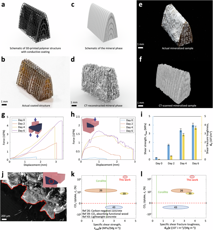
a, b Schematic of the 3D-printed polymer structure with conductive coating and the actual coated structure. c, d Schematic of the formed mineral phase and the actual mineral phase reconstructed from the CT scanning. e An image of the actual coral-inspired mineralized composite sample and (f) the corresponding 3D image constructed from the CT scanning. g Force-displacement curves of coral-inspired mineralized composites under unnotched two-section compact shear tests. The inset shows the schematic for the unnotched two-section compact shear test. h Force-displacement curves of coral-inspired mineralized composites under notched single-section compact shear tests. The inset shows the schematic for the notched single-section compact shear test. i Shear strength (τmax) and shear fracture toughness (GII) of coral-inspired mineralized composites with various electrochemical reaction days. j The morphology of the fracture interface of the coral-inspired mineralized composite under the notched single-section compact shear test. The fracture interface is imaged with SEM. The inset shows the crack location in the notched single-section compact shear test. k Ashby diagram of CO2 uptake (rc) versus specific shear strength (τmax/ρ) and (l) Ashby diagram of CO2 uptake (rc) versus specific shear fracture toughness (GII/ρ) of the coral-inspired structure (Day 6) compared with natural nacre and other state-of-the-art carbon-reducing composites. The numbers in circles are reference numbers.
The mineralized structural composite with alternating mineral-polymer phases is expected to feature outstanding mechanical performance in resisting the shear loads. To experimentally prove this, we employ unnotched two-section compact shear tests to measure the shear strengths (Fig. 3g, S6a) and notched single-section compact shear tests to measure the shear fracture toughness (Fig. 3h, S6b) of the fabricated mineralized composites over various reaction durations. After complete mineralization for 6 days, the shear strength increases by 17.5 times and the shear fracture toughness enhances by 74 times (Fig. 3i). The shear fracture toughness of the mineralized composite is also 102 times higher than that of the CaCO3 mineral phase (Fig. S7a) and 81 times higher than that of the polymer phase (Fig. S7b). To reveal the mechanism for the high shear fracture toughness, we employ SEM to image the cracking surface after the notched single-section compact shear tests and find a clear zig-zag crack propagation pathway (Fig. 3j). The observed curved crack propagation pathway assists the mineralized composite to dissipate a large amount of energy during the fracture process, thus exhibiting a high fracture toughness of the composite41,42.
To compare the mechanical performance and CO2 uptaking capability of the proposed mineralized composites with those of the state-of-the-art carbon-reducing composites, we present the material property charts for specific shear strength (i.e., shear strength per unit density), CO2 uptaking rate (see Materials and Methods for calculation method), and specific shear fracture toughness (i.e., shear fracture toughness per unit density) in Fig. 3k, l. Compared to the state-of-the-art carbon-reducing composites, including lightweight concrete with reduced carbon emissions43, carbon-negative concrete26, and CO2-absorbing functional wood39, both specific shear strength and specific shear fracture toughness of the mineralized composites are comparable to the highest existing performances (i.e., of CO2-absorbing functional wood39), while the CO2 uptaking rate is an order of magnitude higher than that of highest existing performance (i.e., of carbon-negative concrete26). Impressively, the specific shear strength of the mineralized composite is 100% higher and the specific shear fracture toughness is 600% higher than those of the natural corallite, respectively26,39,40,44,45,46,47,48,49,50.
Multifunctionalities of the proposed paradigm
Besides exceptional mechanical performance and CO2 uptaking capability, the proposed electrochemical manufacturing method and the fabricated mineralized composites feature several interesting functionalities (Fig. 4). First, the mineralized composite can be facilely programmed by freely designating the mineralization region of the 3D-printed lattice structure via selectively coating conductive layers (Fig. 4a–c). For example, a rectangular polymer lattice structure is coated only at both ends, ensuring that mineralization occurs exclusively at these two locations during the electrochemical process (Fig. 4a, b). Upon compressing this structure, a distinct variance in the deformation is observed, affirming the notable difference in structure stiffness (Fig. 4c). In addition, in contrast to most existing manufacturing methods that are typically not reversible, the electrochemical manufacturing process proposed in this work is fully reversible (Fig. 4d–g). When a mineralized composite sample is submerged in a hydrochloric acid solution (1 mol/L), the mineral phase can be dissolved within 10 min (Fig. 4d, e) and the resulting demineralized lattice can be re-mineralized with the electrochemical process (Fig. 4f, g), which does not require the redeposition of a conductive layer. Moreover, though the 3D-printed polymer is not fire-retardant, the mineralized composite is found to feature an exceptional fire-retardant property (Fig. 4h–k). As shown in Fig. 4h–j, the shape of a mineralized sample does not evidently change after being placed on fire for 30 min. The mechanical performance of the mineralized sample after burning for 30 min is also mostly equivalent to that of the sample before burning. We hypothesize that fire-retardant performance is probably attributed to the fire-quenching effect of the released CO2 when decomposing small amounts of CaCO3 minerals under high temperatures (Fig. S8)51,52. Furthermore, the mineralized composites, if damaged, can be repaired by triggering the electrochemical process around the damage interface (Fig. 4l–m). We take a mineralized composite and break it into two segments. These two segments are later fastened together and finally fused together through the mineralization upon application of our electrochemical process on the interface (Figs. 4l, S9). The repaired composite is loaded with three-pointing bending and its flexural strength can attain 60.5% of that of the unbroken original sample (Fig. 4m).

a–c Structure-programmability: a Schematic to show a sandwich sample with polymer lattice in the center and mineralized regions at two ends. b, c Fabricated sandwich sample before and after compression. d–g Process-reversibility: d Fabricated mineralized composite sample. e The sample submerged in a hydrochloric acid solution (1 mol/L). f Demineralized sample after removing the CaCO3 mineral phase. g Re-mineralized composite sample with the proposed electrochemical manufacturing process. h–k Fire-resistance: h, i The mineralized composite sample after being put on fire for 5 min and 30 min. j The mineralized composite sample after being fire-burned for 30 min. k Force-displacement curves of unnotched two-section compact shear tests for the mineralized composite before and after being fire-burned for 30 min. The inset shows the schematic for the unnotched two-section compact shear test. l, m Crack-repairability: l Mineralized composite sample at different states of the electrochemical mineralization enabled crack repairing. m Force-displacement curves of three-point bending tests for the mineralized composite at the original state and after being repaired. The inset shows the schematic for the three-point bending test.
Modular assembly enabled scaling-up of the mineralized composites
One promising vision is to extend the proposed electrochemical manufacturing paradigm to construct future prefabricated carbon-negative buildings. The prefabrication approach is appealing because it can drastically reduce CO2 emissions compared to on-site construction53,54,55,56. Besides, the buildings are expected to continuously sequester CO2 from the atmosphere to strengthen the buildings’ mechanical strength and resistance (Fig. 5a). Despite the promise, one key challenge is how to scale up the fabricated mineralized composite structure.

a–c Schematics of the future carbon-negative building: The carbon-negative building (a) is constructed by modular assembly of carbon-negative units (b) with both organic and mineral phases (c). d 3D-printed polymer unit. e 3D-printed unit coated with a conductive Pd layer. f Mineralized carbon-negative unit fabricated with the proposed electrochemical manufacturing process. g Assembled two carbon-negative units for tensile and shear tests. The testing directions are shown as respective arrows and the dashed line shows the connected surface. h Force-displacement curves of the assembled two units with various electrochemical mineralization durations under tensile tests. i Force-displacement curves of the assembled two units with various electrochemical mineralization durations under shear tests. j Tensile strength (σmax) and shear strength (τmax) of assembled two units with various electrochemical mineralization durations. k Force-displacement curve of a plate assembled with 16 carbon-negative units under a concentrated load in the center. The inset shows the loading on the assembled plate. l A 3D dome structure assembled from 16 carbon-negative units. The insets show the CAD model of the dome structure and 16 dissembled units. m A 3D house structure assembled from 31 units of 4 categories and the corresponding 4 categories of units. n The assembled house structure withstanding a weight (300 g) equivalent to 176 times its own weight.
To address the scaling-up challenge, we propose to employ a modular assembly method that large-scale structures can be fabricated by assembling small-scale puzzle modules of the mineralized composite (Fig. 5b, c). To demonstrate the concept, we fabricate exemplary puzzle modules by first 3D-printing polymer structure units (Fig. 5d), then coating the units with a thin conductive Pd layer (Fig. 5e), and finally mineralizing the units with the proposed electrochemical manufacturing (Fig. 5f). To examine the modular connectivity, we measure the tensile and shear strength of the assembled two units (Fig. 5g–j). Following a 6-day reaction duration, the tensile and shear strength of the connection increase by 27 and 11 times, respectively (Fig. 5j). The tensile strength of the assembled units is in the same order as flexural strength obtained in Fig. 2g and the shear strength is in the same order of the shear strength obtained in Fig. 3g. Finite element simulations reveal that maximum stress is located at the neck region of the connection (Fig. S10). The mineralized neck regions, with high mechanical resistance, ensure a safe connection between puzzle modules. To further evaluate the robustness of the assembled structure, we measure the out-of-plane resistance of a sixteen-assembled-unit plane and find it could resist an out-of-plane force equivalent to 50 times its own weight (Fig. 5k). To demonstrate the feasibility of the modular assembly method in fabricating 3D structures with curved surfaces, we construct a dome model by assembling 16 curved units (Fig. 5l). To further evaluate the molecular assembly method in fabricating future buildings, we build up a house model by assembling 31 units of 4 categories (Fig. 5m). The house model can withstand a load equivalent to 176 times its own weight (Fig. 5n).
Discussion
In summary, we present an electrochemical manufacturing method to sequester CO2 to fabricate coral-inspired structural composites with exceptional mechanical properties. Different from most carbon sequestration methods that only store CO2 or convert CO2 into liquid substances, the coral-inspired manufacturing method turns undesirable atmospheric CO2 into load-bearing strong solid composites (Table S1). Compared to an existing method that utilizes CO2 to fabricate low/negative carbon concrete26, our method not only enables structures with designed microarchitectures but also features a 25-times higher carbon sequestration efficiency (i.e., captured CO2 mass per unit volume over carbon sequestration timescale shown in Table S1). This paradigm may lead to a research area where diverse new manufacturing methods are proposed to sequester CO2 to fabricate functional solids for various engineering applications. Besides, our paradigm in this work not only enables the fabricated structural composites with exceptional mechanical strength and toughness but also opens opportunities to fabricate hybrid structural composites like sophisticated bouligand structures57 and nacre-like structures58. Moreover, our fabricated structural composites also exhibit unusual functions such as fire-resistance and crack-repairability. Along with the proposed modular assembly method to scale up the proposed carbon-reducing composites, the proposed paradigm may find broad applications in future engineering structures where both structural reliability and carbon footprint should be synergistically considered.
Methods
Materials
Clear V4, a transparent 3D-printing resin, was sourced from Formlabs. A CO2 generator from WuyouChy generated gaseous CO2 for the project. The acetone and calcium chloride were purchased from Sigma-Aldrich. The platinum electrode was purchased from TizZo.
Preparation of 3D-printed structure
To fabricate the 3D-printed structure, we employed Clear V4 resin in the stereolithography process using a Form 3 + 3D printer. A computer-aided design (CAD) model was sliced into sequential images projected onto a liquid basin, with the exposed resin solidified by light exposure to form a bonded solid layer on the printing stage. By repeatedly lifting the printing stage to a prescribed height and illuminating the resin with another slice image, additional layers were printed and bonded onto the previous layers until the entire structure was complete. Each layer was set at a thickness of 25 µm and took 83 s to solidify. Following the 3D-printing process, the resulting polymer was washed with acetone and air-dried for 24 h at 25 °C to remove any residual solvent.
Sputter Coating of 3D-printed structure
The 3D-printed polymer structures were coated with palladium using a Cressington 108 Manual Sputter Coater. After loading the sample into the coater and securing the top plate, the power was set to 30 mA. The chamber was evacuated to a pressure below 0.05 mbar. To eliminate residual oxygen and water vapor, the chamber was flushed with argon at 0.4 mbar for 20 s. Subsequently, the argon pressure was adjusted to 0.08 mbar, and the sputtering process was carried out for 20 s for one side. To achieve a uniform palladium coating, the sample was rotated to the other 3 sides and coated for another 20 s for each side.
Electrochemical manufacturing of mineralized composites
The coated 3D-printed structure served as the cathode, while a platinum electrode acted as the anode, with both immersed in the calcium chloride solution (1 mol/L) (Fig. S2). Two electrodes were then connected to a 6 V power supply, while the gaseous CO2 was pumped through the calcium chloride solution. During the electrochemical reaction, the cathode generated hydroxide ions by electrolyzing water. The hydroxide ions reacted with the bicarbonate ions produced from the hydrolysis of CO2 to form carbonate ions, which further reacted with calcium ions to produce calcium carbonate. Over 6 days, the calcium carbonate minerals were gradually precipitated out and firmly adhered to the internal surface of the cathode lattice.
Calculation of CO2 uptaking
The CO2 uptaking was calculated using the following equation26,
where ({M}_{{rm{mineralized; composite}}}) and ({M}_{3{rm{D}}-{rm{printed; polymer}}}) were the measured mass of mineralized composites and 3D-printed polymer, respectively; and ({m}_{{{rm{CO}}}_{2}}) and ({m}_{{{rm{CaCO}}}_{3}}) were the molar mass of CO2 and CaCO3, respectively.
Calculation of carbon footprint of the mineralized composite
The carbon footprint of the mineral phase was calculated as:
where ({M}_{{rm{mineralized; composite}}}) and ({M}_{3{rm{D}}-{rm{printed; polymer}}}) are the mass of the mineralized composite and 3D-printed polymer, ({C{O}_{2}}_{{{rm{CaCl}}}_{2}},)(around 38.6 g CO2eq/kg59) is the carbon footprint of calcium chloride per kilogram, ({m}_{{{rm{CO}}}_{2}}), ({m}_{{{rm{CaCl}}}_{2}}) and ({m}_{{{rm{CaCO}}}_{3}}) are the molar mass of carbon dioxide, calcium chloride, and calcium carbonate, ({rho }_{{{rm{CaCl}}}_{2}}) is the density of calcium chloride and ({rho }_{3{rm{D}}-{rm{printed; polymer}}}) is the bulk density of 3D-printed structural polymer (see Supplementary methods for the calculation method). Plugging the carbon footprint of the polymer phase60 and the consumed electricity in California, the total carbon footprint of the mineralized composite can be written as:
where ({C{O}_{2}}_{{rm{electricity}}}) denotes the carbon footprint of electricity per kilowatt-hour in California (0.22 kg CO2eq/kWh61), (E) denotes the electricity quantity consumed per unit volume of mineralized composites in kilowatt-hours (60-100 ({{rm{kWh}}/{rm{m}}}^{3}) for our experiment), ({C{O}_{2}cdot rho }_{{rm{polymer}}}) denotes the carbon footprint of the polymer phase and ({rho }_{{rm{polymer}}}) denotes the density of polymer phases.
Characterization of mineralized composites
The mineralized composites were imaged with a Nikon camera, a Nikon microscope, a scanning electron microscope (Nova NanoSEM 450), and a Micro-CT instrument (Nikon/XT H 225 ST), respectively.
Mechanical testing of mineralized composites
Young’s modulus of the mineralized composite was measured via the compression test using an Instron mechanical tester (Fig. 2f) The flexural strength of the mineralized beam was measured via the three-point bending test using the Instron mechanical tester (Fig. 2g). The flexural strength was determined by using σmax = 3SFmax/(2BW2)62, where S denotes the span length, B represents the width of the sample, and W represents the depth of the sample. The shear strength of the coral-like mineralized composites was measured via unnotched two-section compact shear tests (Fig. 3g, S6a). The shear strength was calculated as τmax = Fmax/(S1 + S2), where Fmax was the maximum load under the compact shear test, and S1 and S2 were the areas of two sections under shear loads. The shear fracture toughness was measured via notched single-section compact shear tests with an initial crack depth of 1 mm (Fig. 3h, +Fig. S6b). The shear toughness was calculated by ({G}_{{rm{II}}}=,frac{{F}_{max }^{2}}{2B}frac{partial C}{partial a})63,64, where B was the thickness, a was the crack length, Fmax was the critical load, and C was the compliance. Compliance values were found from the inverse slope of the load versus displacement curves of the shear fracture toughness tests. Tensile and shear tests on two assembled units (Fig. 5g) and concentrated loading on the 16-unit plate (Fig. 5k) were carried with the Instron mechanical tester.
Selected mineralization
A rectangular polymer lattice structure was initially designed using computer-aided design (CAD) software and subsequently 3D-printed with Clear-V4 resin. During the palladium coating process using a Cressington 108 Manual Sputter Coater, the central part of the structure was masked to ensure that only the ends were coated. These two ends were then connected to a voltage source to function as a cathode, resulting in mineralization occurring solely at these sites during the electrochemical process (Fig. 4a, b).
Reversibility of electrochemical mineralization
A mineralized composite sample was submerged in a hydrochloric acid solution (1 mol/L) for 10 min (Fig. 4d, e), and the resulting demineralized lattice was then re-mineralized via the same electrochemical methods (see Electrochemical manufacturing of mineralized composites for the manufacturing method) (Fig. 4f, g).
Fire resistance test
A mineralized sample was placed on fire for 30 min and then tested via the unnotched two-section compact shear test with the Instron mechanical tester (Fig. 4h–j).
Crack-healing
We took a mineralized composite and broke it into two segments. These two segments were later fastened together while being connected to a voltage of 6 V to function as a cathode, resulting in mineralization occurring at the interface over 6 days (Fig. 4l, S9).
Finite element simulation of two assembled units
The finite element simulation of the two assembled units was carried out using ABAQUS. The simulations utilized 3D deformable element types. The total number of elements used was 172,332. The material properties were specified as follows: Young’s modulus of 400 MPa and Poisson’s ratio of 0.3. The result accuracy were verified by refining the mesh.
Responses