Unconventional angular dependence of spin-orbit torque-induced harmonic Hall resistance in Pt/YIG bilayers

Introduction
Spin-orbit torque (SOT), a type of spin torque caused by spin-orbit coupling-induced spin currents1,2,3, enables the efficient electrical manipulation of magnetization in various spintronic devices. In particular, SOT provides a fast and energy-efficient means by which to realize current-induced magnetization switching4,5 and domain wall motion6,7, both of which can be exploited for magnetic random-access memory8,9, spin Hall nano-oscillators10,11, true random number generators12, magnonic devices13, and neuromorphic computing devices14, among others. When applying a charge current in a typical heavy-metal (HM)/ferromagnet (FM) heterostructure, there are two main mechanisms responsible for SOT. The first is the spin Hall effect, generating a transverse spin current in the HM layer2,15. The second is the Rashba-Edelstein effect, inducing spin accumulation at the HM/FM interface with broken inversion symmetry16,17. These effects cause spin torque and control the magnetization direction. Moreover, the HM/FM heterostructures give rise to a magnetoresistance based on the spin Hall effect-induced spin current in HM and the subsequent reflection of the spin current at the FH/HM interface via the inverse spin Hall effect. This is known as spin Hall magnetoresistance, which can be employed to study the spin-to-charge current conversion in HM/FM heterostructures. Various materials, including HMs2,18 and their alloys19,20, Weyl semimetals21,22, and topological insulators23,24,25, have been investigated as spin current sources, along with their combinations with FM (or antiferromagnetic) materials, as part of the effort to pursue high charge-to-spin conversion efficiency1.
The characterization of SOT is a pivotal task in the development of SOT materials in spintronic applications. One of the most widely used methods to determine the magnitude and direction of SOTs is to analyze the first and second harmonic Hall resistances (({R}_{{xy}}^{1omega }) and ({R}_{{xy}}^{2omega }))2,26. When an AC current (J={J}_{0}sin omega t) is applied to the HM/FM heterostructure, SOTs induces magnetization oscillation with a modulation amplitude of (Δθ, Δϕ) from the corresponding equilibrium direction (θ, ϕ) under an external magnetic field, where ({J}_{0}) and ω are the amplitude and angular frequency of the AC current density, and θ and ϕ are the polar and azimuthal angles of magnetization, respectively (see Fig. 1a). ({R}_{{xy}}^{1omega }) indicates the magnetization direction through the planar Hall effect (PHE, ({R}_{{rm{PHE}}})) and anomalous Hall effect (AHE, ({R}_{{rm{AHE}}})), while ({R}_{{xy}}^{2omega }) is mainly caused by the oscillation of magnetization due to SOT27,28,29. For FM with in-plane magnetization, as studied here, ({R}_{{xy}}^{1omega }) and ({R}_{{xy}}^{2omega }) can be described in terms of the azimuthal angle ϕ only (see details in the Supplementary Note 1),
Here, ({c}_{2kphi }^{1omega }) and ({c}_{left(2k-1right)phi }^{2omega }) (where (k=mathrm{1,2,3,4})) are the current- and field-dependent coefficients (Supplementary Note 1). Note that we ignore higher-order terms (k > 4) in this study. Given that ({R}_{{xy}}^{1omega }) (({R}_{{xy}}^{2omega })) is an even (odd) function with respect to ({J}_{0}), ({R}_{{xy}}^{1omega }) (({R}_{{xy}}^{2omega })) contains only even (odd)-number nϕ symmetric terms (Supplementary Note 2). In a small current regime where higher-order terms are neglected, ({R}_{{xy}}^{1omega }) (({R}_{{xy}}^{2omega })) exhibits sin 2ϕ (cos ϕ and cos 3ϕ) behavior, leading to the following equations,
where ({c}_{2phi }^{1omega },approx, {R}_{{rm{PHE}}}), ({c}_{1phi }^{2omega },approx, {R}_{{xy}}^{{rm{SSE}}}+frac{{R}_{{rm{AHE}}}{H}_{{rm{DL}}}}{2{H}_{{rm{eff}}}}+frac{{R}_{{rm{PHE}}}}{2}frac{{H}_{{rm{FL}}}+{H}_{{rm{Oe}}}}{{H}_{{rm{a}}}}), and ({c}_{3phi }^{2omega },approx, frac{{R}_{{rm{PHE}}}}{2}frac{{H}_{{rm{FL}}}+{H}_{{rm{Oe}}}}{{H}_{{rm{a}}}}); ({H}_{{rm{eff}}}) is the effective field including the applied field ({H}_{{rm{a}}}) and the demagnetization and anisotropy fields of the FM layer, and ({H}_{{rm{DL}}}), ({H}_{{rm{FL}}}), and ({H}_{{rm{Oe}}}) are the damping-like (DL) and field-like (FL) effective fields of the SOT and Oersted fields, respectively. ({R}_{{xy}}^{{rm{SSE}}}) is the spin Seebeck effect (SSE) contribution. Note that these equations have been widely employed to characterize SOTs in various materials systems30,31,32,33. We want to emphasize that the characterization of SOT using harmonic Hall resistance measurements has mainly been conducted in a low-current regime, where higher order terms are negligible. However, SOT-induced magnetization switching or auto-oscillation, which are relevant for device applications, occur at the high-current regime, where the higher order terms can be non-trivial. A recent study34 reported the measurement of high-order angular dependence in the third harmonic Hall resistance of Pt/α-Fe2O3 at a current density of (1.6times {10}^{11}{rm{A}}/{{rm{m}}}^{2}). This was attributed to the DL SOT of the sample, where the DL SOT terms in the second harmonic Hall resistance ({R}_{{xy}}^{2omega }) are canceled out due to the alternating antiferromagnetic moments of α-Fe2O3. This result suggests that the higher-order angular-dependent terms in Eqs. (1) and (2) may appear in a high-current regime even in FM, which is the main theme of this study.

a, b, Schematic illustration (a) and optical microscopy image (b) of the Pt (3 nm)/YIG (30 nm) Hall-bar sample. The bottom of Fig. 1a indicates the SOT-induced oscillation of magnetization m with a modulation amplitude of (left(Delta theta ,Delta phi right)) around a magnetic field (({H}_{{rm{a}}})). Current is injected in the x direction. An external magnetic field ({H}_{{rm{a}}}) is applied on the x–y plane. c, d, Angular dependences of ({R}_{{xy}}^{1omega }) (c) and ({R}_{{xy}}^{2omega }) (d) measured at ({H}_{{rm{a}}}=45), 85 and 280 Oe. Note that constant offsets are subtracted from the ({R}_{{xy}}^{1omega }) and ({R}_{{xy}}^{2omega }) plots. e, f, ({R}_{cos phi }^{2omega }) (e) and ({R}_{left[2{cos }^{3}phi -cos phi right]}^{2omega }) (f) as a function of (1/{H}_{{rm{eff}}}) and (1/{H}_{{rm{a}}}), respectively. The solid lines indicate the linear fitting results. The data for c–f were obtained at ({J}_{0}=8.3times {10}^{10},{rm{A}}/{{rm{m}}}^{2}).
Here, we report a systematic study of azimuthal angle (ϕ)-dependent harmonic Hall resistances in a Pt/yttrium iron garnet (Y3Fe5O12: YIG) layer investigated under a wide range of measurement currents. Under low-current conditions, we observed conventional ϕ-dependent behavior in ({R}_{{xy}}^{1omega }) and ({R}_{{xy}}^{2omega }), well described by Eqs. (3) and (4), respectively. On the other hand, as the current increases, the ϕ dependencies of ({R}_{{xy}}^{1omega }) and ({R}_{{xy}}^{2omega }) deviate significantly from the corresponding conventional shapes. This is evidenced by the saw-tooth-wave-like (in ({R}_{{xy}}^{1omega })) and the square-wave-like (in ({R}_{{xy}}^{2omega })) curves, where the higher-order terms become non-negligible. For example, at a current density of ({J}_{0}=2times {10}^{11}{rm{A}}/{{rm{m}}}^{2}), the magnitude of the 4ϕ (5ϕ) term of ({R}_{{xy}}^{1omega }) (({R}_{{xy}}^{2omega })) can be as high as 30% (20%) of that of the lowest 2ϕ (1ϕ) term. We attribute this unconventional ϕ-dependence of ({R}_{{xy}}^{1omega }) and ({R}_{{xy}}^{2omega }) to nonlinear response of magnetization direction to SOTs. This result will contribute to advancing the understanding of magnetization dynamics during the SOT-induced switching of magnetization under large currents.
Results
Harmonic Hall resistances in a low-current regime
First, we check the conventional behaviors of ({R}_{{xy}}^{1omega }) and ({R}_{{xy}}^{2omega }) in a Pt (3 nm)/YIG (30 nm) layer in a low-current regime (({J}_{0}, < ,1times {10}^{11}{rm{A}}/{{rm{m}}}^{2})). Here, YIG film was grown on a GGG (111) substrate by means of RF sputtering at room temperature, followed by a post-annealing step at 750 °C in an oxygen environment for two hours. Details of the sample growth conditions are provided in the Methods section. The grown YIG film exhibits good crystallinity well matched to the GGG substrate (Supplementary Note 3) and in-plane magnetic anisotropy (Supplementary Note 4). Figure 1b shows an image of the Hall bar device. Figure 1c, d show the ({R}_{{xy}}^{1omega }) and ({R}_{{xy}}^{2omega }) of the sample measured at a current density of (8.3times {10}^{10}{rm{A}}/{{rm{m}}}^{2}) with different magnetic fields (({H}_{{rm{a}}})). Note that even in a Pt/YIG film with an insulating FM, where the current flows only in the non-magnetic Pt, ({R}_{{xy}}^{1omega }) depends on the magnetization direction of YIG due to the spin Hall magnetoresistance27,35, the magnetic proximity effect in Pt36,37,38, and interfacial spin-dependent scattering39. Note that the angular dependence of the longitudinal resistances of the sample was also measured, corresponding to spin Hall magnetoresistance (unidirectional spin Hall magnetoresistance) with a magnitude of 0.036% ((2.3times {10}^{-4} %)) at ({J}_{0}=1times {10}^{11}{rm{A}}/{{rm{m}}}^{2}) and ({H}_{{rm{a}}}=25) Oe for the first (second) harmonic resistance (Supplementary Note 5). Figure 1c shows the angular dependence of ({R}_{{xy}}^{1omega }), identical in all cases regardless of the magnitude of ({H}_{{rm{a}}}) and thus exhibiting typical sin 2ϕ behavior of PHE. This indicates that the magnetization of the YIG coherently rotates following the ({H}_{{rm{a}}}). On the other hand, Fig. 1d shows the angular dependence of ({R}_{{xy}}^{2omega }), demonstrating clear dependence on ({H}_{{rm{a}}}). This is expected from Eq. (4), indicating that the ({H}_{{rm{a}}}) contribution to ({R}_{{xy}}^{2omega }) overtakes that of the SOT-induced effective fields (({H}_{{rm{DL}}}), ({H}_{{rm{FL}}})) for a large ({H}_{{rm{a}}}). To obtain ({H}_{{rm{DL}}}) and ({H}_{{rm{FL}}}), we separated the cos ϕ and (left[2{cos }^{3}phi -cos phi right]) components and then plotted the extracted ({R}_{cos phi }^{2omega }) and ({R}_{left[2{cos }^{3}phi -cos phi right]}^{2omega }) values as a function of (1/{H}_{{rm{eff}}}) and (1/{H}_{{rm{a}}}), respectively (Fig. 1e, f). From the slopes of the ({R}_{cos phi }^{2omega }) and ({R}_{left[2{cos }^{3}phi -cos phi right]}^{2omega }) versus (1/{H}_{{rm{eff}}}) and (1/{H}_{{rm{a}}}) curves, the values of (left({H}_{{rm{FL}}}+{H}_{{rm{Oe}}}right)=0.93) Oe, ({H}_{{rm{DL}}}=10.1) Oe were extracted at ({J}_{0}=1times {10}^{11}{rm{A}}/{{rm{m}}}^{2}). Note that we obtained a value of ({R}_{{rm{AHE}}}=2.7{rm{m}}Omega) (Supplementary Note 6) and the y-intercept of the ({R}_{cos phi }^{2omega }) vs (1/{H}_{{rm{eff}}}) plot (Fig. 1e) indicates the SSE component (({R}_{{xy}}^{{rm{SSE}}})). These behaviors are consistent with those in the previous reports30.
Harmonic Hall resistances in a high-current regime
Next, we examined the angular dependence of ({R}_{{xy}}^{1omega }) and ({R}_{{xy}}^{2omega }) in the high-current regime, exhibiting behaviors different from those in low-current regimes. Figure 2a, b display the results measured for three different current densities, ({J}_{0}=mathrm{0.5,1.0},{rm{and}},2.2times {10}^{11}{rm{A}}/{{rm{m}}}^{2}) Here, ({H}_{{rm{a}}}=25{rm{Oe}}). As the current increases, the ϕ dependencies of ({R}_{{xy}}^{1omega }) and ({R}_{{xy}}^{2omega }) deviate significantly from the conventional shapes shown in Fig. 1. Interestingly, they started to resemble saw-tooth wave form (in ({R}_{{xy}}^{1omega })) and square-wave form (in ({R}_{{xy}}^{2omega })) curves at ({J}_{0}sim 2.2times {10}^{11},{rm{A}}/{{rm{m}}}^{2}), which cannot be explained using Eqs. (3) and (4). Therefore, to account for the experimental data, we used Eqs. (1) and (2). The decomposed nϕ ((n=1,,2,ldots ,8)) angular-dependent curves are indicated by the colored lines in Fig. 2a, b. Notably, as the current increases, the higher-order angular components of 4ϕ, 6ϕ and 8ϕ (5ϕ and 7ϕ) in ({R}_{{xy}}^{1omega }) (({R}_{{xy}}^{2omega })) becomes non-negligible, indicating that higher-order terms should be considered when analyzing SOT-induced harmonic Hall resistances. Note that we estimated the increase in the sample temperature to be approximately 30 K at ({rm{j}}=1.7times {10}^{11}{rm{A}}/{{rm{m}}}^{2}) by analyzing the resistance of Pt versus current (Supplementary Note 7). Considering the Curie temperature of bulk YIG (560 K)40 is far above room temperature, such increased ΔT might not significantly change the magnetization.
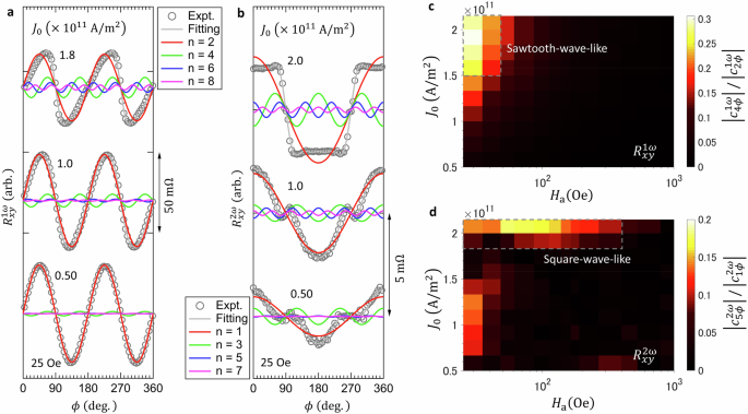
({R}_{xy}^{1omega }) a, b, Angular dependences of ({R}_{{xy}}^{1omega }) (a) and ({R}_{{xy}}^{2omega }) (b) at Ha = 25 Oe for three different current densities. The grey solid curve indicates the fitting result, and the curves shown in red, green, blue and pink indicate the ({c}_{nphi }sin left(nphi right)) ((n=mathrm{2,4,6,8})) components of ({R}_{{xy}}^{1omega }) (a) and the ({c}_{nphi }cos left(nphi right)) ((n=mathrm{1,3,5,7})) components of ({R}_{{xy}}^{2omega }) (b), as obtained from fitting using Eqs. (1) and (2). c, d, the ({J}_{0}-{H}_{{rm{a}}}) diagrams of absolute values of the lowest-order unconventional angular-dependent coefficients, (left|{c}_{4phi }^{1omega }right|) (c) and (left|{c}_{5phi }^{2omega }right|) (d), normalized by the leading terms (left|{c}_{2phi }^{1omega }right|) and (left|{c}_{1phi }^{2omega }right|), respectively.
To gain a quantitative understanding of the higher-order terms, we repeated the harmonic Hall resistance measurements under various current levels ((0.5times {10}^{11}le {J}_{0}le 2.2times {10}^{11},{rm{A}}/{{rm{m}}}^{2})) and magnetic fields ((25,{rm{Oe}}le {H}_{{rm{a}}}le 10,{rm{kOe}})) [Supplementary Note 8]. Figure 2c, d display the absolute values of the lowest-order unconventional angular-dependent coefficients, (left|{c}_{4phi }^{1omega }right|) and (left|{c}_{5phi }^{2omega }right|) (normalized by the leading terms (left|{c}_{2phi }^{1omega }right|) and (left|{c}_{1phi }^{2omega }right|), respectively) as functions of ({J}_{0}) and ({H}_{{rm{a}}}). These results demonstrate that the magnitudes of (left|{c}_{4phi }^{1omega }right|) and (left|{c}_{5phi }^{2omega }right|) become significant under large currents and small external fields, where saw-tooth-wave-like (in ({R}_{{xy}}^{1omega })) and square-wave-like (in ({R}_{{xy}}^{2omega })) angular-dependent curves are observed in Fig. 2a, b. Note that these (left|{c}_{4phi }^{1omega }right|) and (left|{c}_{5phi }^{2omega }right|) values are suppressed as ({H}_{{rm{a}}}) increases, suggesting that they originate from the SOT-induced magnetization oscillation. The magnitude of (left|{c}_{4phi }^{1omega }right|) ((left|{c}_{5phi }^{2omega }right|)) can reach about 30% (20%) of that of the leading term (left|{c}_{2phi }^{1omega }right|) ((left|{c}_{1phi }^{2omega }right|)) at ({J}_{0}sim 2times {10}^{11},{rm{A}}/{{rm{m}}}^{2}). These unconventional angular-dependent (nphi left(nge 4right)) terms ultimately changed the angular dependence of ({R}_{{xy}}^{1omega }) and ({R}_{{xy}}^{2omega }).
Figure 3 shows the current dependence of the coefficients ({c}_{nphi }^{2omega }) ((n=1,,3,,5,,7)) in ({R}_{{xy}}^{2omega }) at ({H}_{{rm{a}}}=25{rm{Oe}}) obtained by fitting the ({R}_{{xy}}^{2omega }) data to Eq. (2). We found that the signs of ({c}_{3phi }^{2omega }), ({c}_{5phi }^{2omega }) and ({c}_{7phi }^{2omega }) change with an increase in ({J}_{0}). This sign reversal can be attributed to the nonlinear response of magnetization to SOT. For example, ({c}_{5phi }^{2omega }) can be described as ({c}_{5phi }^{2omega }=-{A}_{1}{J}_{0}^{3}+{A}_{2}{J}_{0}^{5}+ldots), where ({A}_{1}) and ({A}_{2}) are the coefficients of the SOT effective fields. The details about ({A}_{1}) and ({A}_{2}) are found in Supplementary Note 1. The sign of ({c}_{5phi }^{2omega }) changes when the second term ({A}_{2}) (proportional to ({J}_{0}^{5})) becomes larger than the first term ({A}_{1}) (proportional to ({J}_{0}^{3})) under a large current. Likewise, the higher-order current dependence causes sign changes of the other coefficients ({c}_{3phi }^{2omega }) and ({c}_{7phi }^{2omega }) as well [see Eqs. S16 and S18 in Supplementary Note 1].
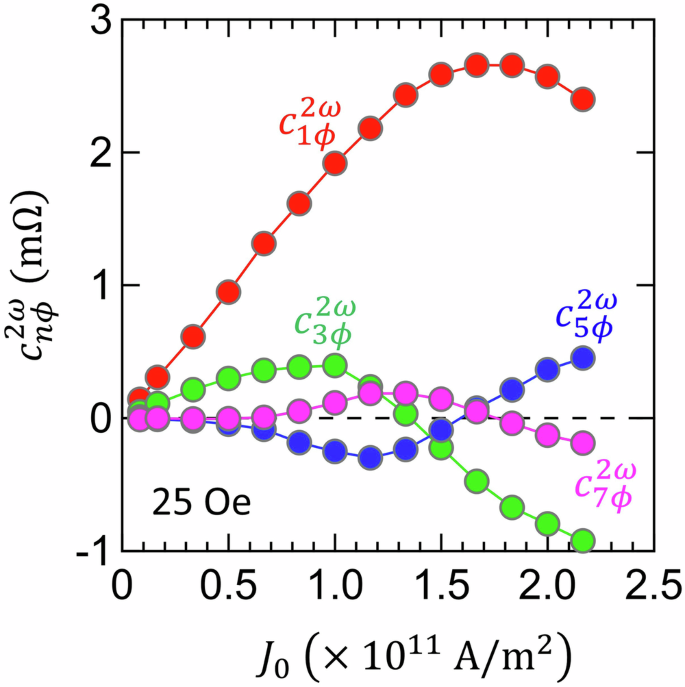
({c}_{nphi }^{2omega }) were obtained by fitting the ({R}_{{xy}}^{2omega }) data at Ha = 25 Oe to Eq. (2).
Discussion
Finally, we discuss the implications of the present results; i.e., the unconventional (nphi) ((nge 4)) angular dependence of ({R}_{{xy}}^{2omega }) is due to the nonlinear response of magnetization to effective SOT fields. When a sample is subjected to SOT, the magnetization m deviates as ({bf{m}}left(theta +Delta theta ,,phi +Delta phi right),approx, {bf{m}}left(theta ,phi right)+frac{d{bf{m}}left(theta ,,phi right)}{dtheta }Delta theta +frac{d{bf{m}}left(theta ,,phi right)}{dphi }Delta phi) + (frac{1}{2}frac{{d}^{2}{bf{m}}left(theta ,,phi right)}{d{theta }^{2}}{left(Delta theta right)}^{2}+frac{1}{2}frac{{d}^{2}{bf{m}}left(theta ,,phi right)}{d{phi }^{2}}{left(Delta phi right)}^{2}+ldots), where Δθ and Δϕ are dominated by the DL and FL SOT fields, respectively (Supplementary Note 1). However, only the linear terms have been considered in conventional SOT characterization studies in low-current regimes thus far. Given that the unconventional angular dependency is directly linked to the nonlinear current dependences including ({J}_{0}^{2}) and ({J}_{0}^{3}) terms, the observation of unconventional angular dependency indicates that the magnetization response to SOT has to be described by linear (Δθ and Δϕ) as well as nonlinear terms (e.g., ({left(Delta theta right)}^{2}), ({left(Delta theta right)}^{3}) and ({left(Delta phi right)}^{2}), ({left(Delta phi right)}^{3}), and so on). Therefore, our results provide a clue with which to understand SOT-induced magnetization dynamics during magnetization switching under a high current, where the nonlinear response of magnetization to the SOT fields can be non-trivial.
We estimated the SOT-induced effective fields ({H}_{{rm{DL}}}) and ({H}_{{rm{FL}}}) using the current dependence of ({c}_{3phi }^{2omega }) in the high current regime, which are ({H}_{{DL}}=32.3) Oe and ({H}_{{FL}}=1.12) Oe, respectively. They are different from the values obtained at the low current regime. Figure S8 shows that these values can aptly explain the experimental data across the wide range of measurement currents whereas the values obtained at a low current significantly deviates at a high current regime (Supplementary Note 9). This indicates that our model, including higher order terms, offers a better fit to the experimental data across a wide measurement current range. However, the quantitative analysis, including comparison with SOT-induced switching current, remains challenging in the current experiment with the Pt/YIG system. Therefore, further investigation is required to correlate the SOT-induced effective fields with SOT-induced magnetization switching.
In summary, we systematically investigated the azimuthal angle (ϕ)-dependent harmonic Hall resistances ({R}_{{xy}}^{1omega }) and ({R}_{{xy}}^{2omega }) of a Pt/YIG bilayer in a wide current range. Under low-current conditions, we observed conventional ϕ-dependent behavior of ({R}_{{xy}}^{1omega }) and ({R}_{{xy}}^{2omega }); the former exhibits sin 2ϕ behavior while the latter consists of cos ϕ and cos 3ϕ terms, associated with damping-like and field-like SOTs, respectively. As the current increases, the ϕ dependencies of ({R}_{{xy}}^{1omega }) and ({R}_{{xy}}^{2omega }) deviate significantly from the conventional curves, where higher-order angular-dependent terms become non-negligible, i.e., sizable sin 4ϕ and sin 6ϕ terms in ({R}_{{xy}}^{1omega }) and the cos 5ϕ and cos 7ϕ terms in ({R}_{{xy}}^{2omega }). It was found that the magnitude of the 4ϕ (5ϕ) term of ({R}_{{xy}}^{1omega }) (({R}_{{xy}}^{2omega })) could reach 30% (20%) of that of the lowest-order 2ϕ (1ϕ) term at a current density of ({J}_{0}=2times {10}^{11},{rm{A}}/{{rm{m}}}^{2}). Our experimental result is in qualitative agreement with the SOT-related equations of ({R}_{{xy}}^{1omega }) and ({R}_{{xy}}^{2omega }) [i.e., Eqs. (1), (2)], suggesting that the unconventional ϕ-dependence of ({R}_{{xy}}^{1omega }) and ({R}_{{xy}}^{2omega }) is due to nonlinear response of magnetization direction to SOTs. Our result will provide a general method by which to analyze SOT-related harmonic Hall resistance and to comprehend SOT-induced magnetization dynamics during SOT-induced switching under large currents.
Methods
Thin film deposition and sample fabrication
The YIG (30 nm) film in this study was grown on a Gd3Ga5O12 (GGG) (111) substrate by RF sputtering (200 W) using a customized off-stoichiometric target, followed by a post-thermal treatment at 750°C in an oxygen-rich environment for two hours. The sputtering target was prepared for the composition of Y and Fe of 3:5.03 using the same method as described in the previous work41. Sputtering was conducted at a working pressure of 15 mTorr with an Ar and O2 mixture gas. Then, Pt (3 nm) films were deposited by DC magnetron sputtering with a working pressure of 0.4 Pa and a power of 30 W at room temperature. Hall-bar patterned devices were fabricated by photolithography and ion milling, and electrical contact pads of Cr (5 nm)/Au (70 nm) layers were defined by additional photolithography and lift-off processes.
AC lock-in harmonic measurement
Harmonic measurements were performed with AC current (frequency of 7 Hz) using lock-in amplifiers (SR830) and a source meter (Keithley 6221). Root mean-square values were used for the current values to calculate the resistance values; i.e., (R=V/left({I}_{0}/sqrt{2}right)), where ({I}_{0}) is the amplitude of the AC current (I={I}_{0}sin left(omega tright)) and V is the measured voltage.


Responses